/


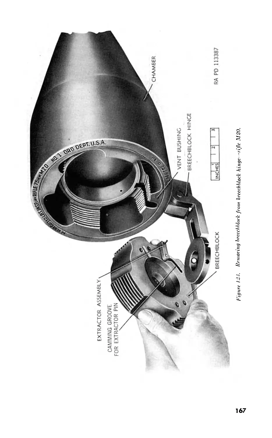
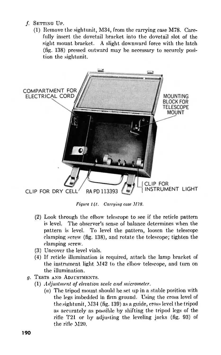


Text
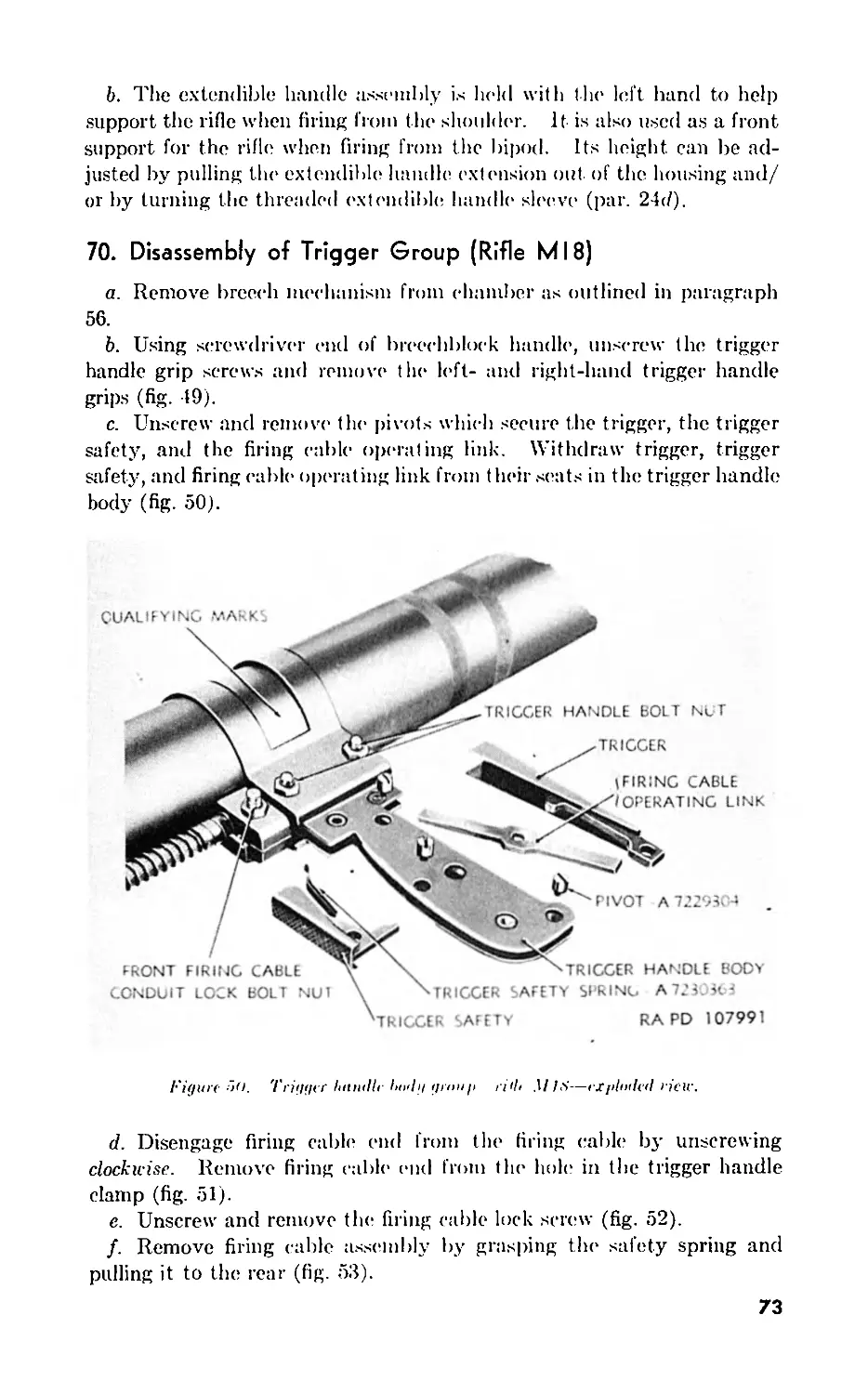
57-mm RIFLES
T15E13 AND M18
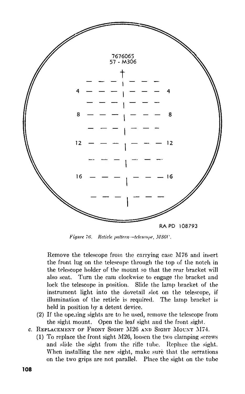
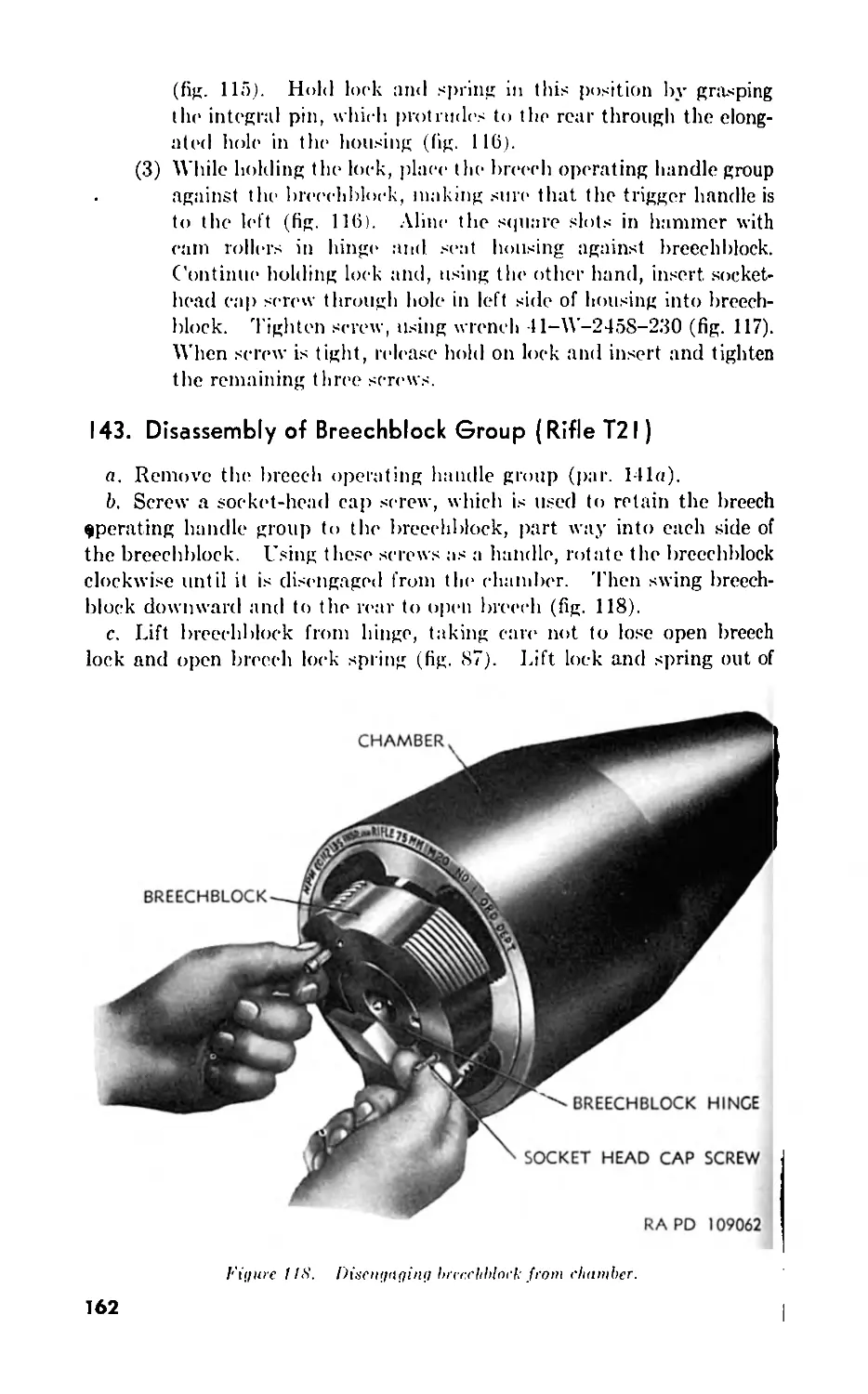
75-mm RIFLES
T21 AND M20 (T25)
RESTRICTED. DISSEMINATION OF RESTRICTED MATTER—No
person is entitled solely by virtue off his grade or position Io
knowledge or possession off classified matter. Such mailer
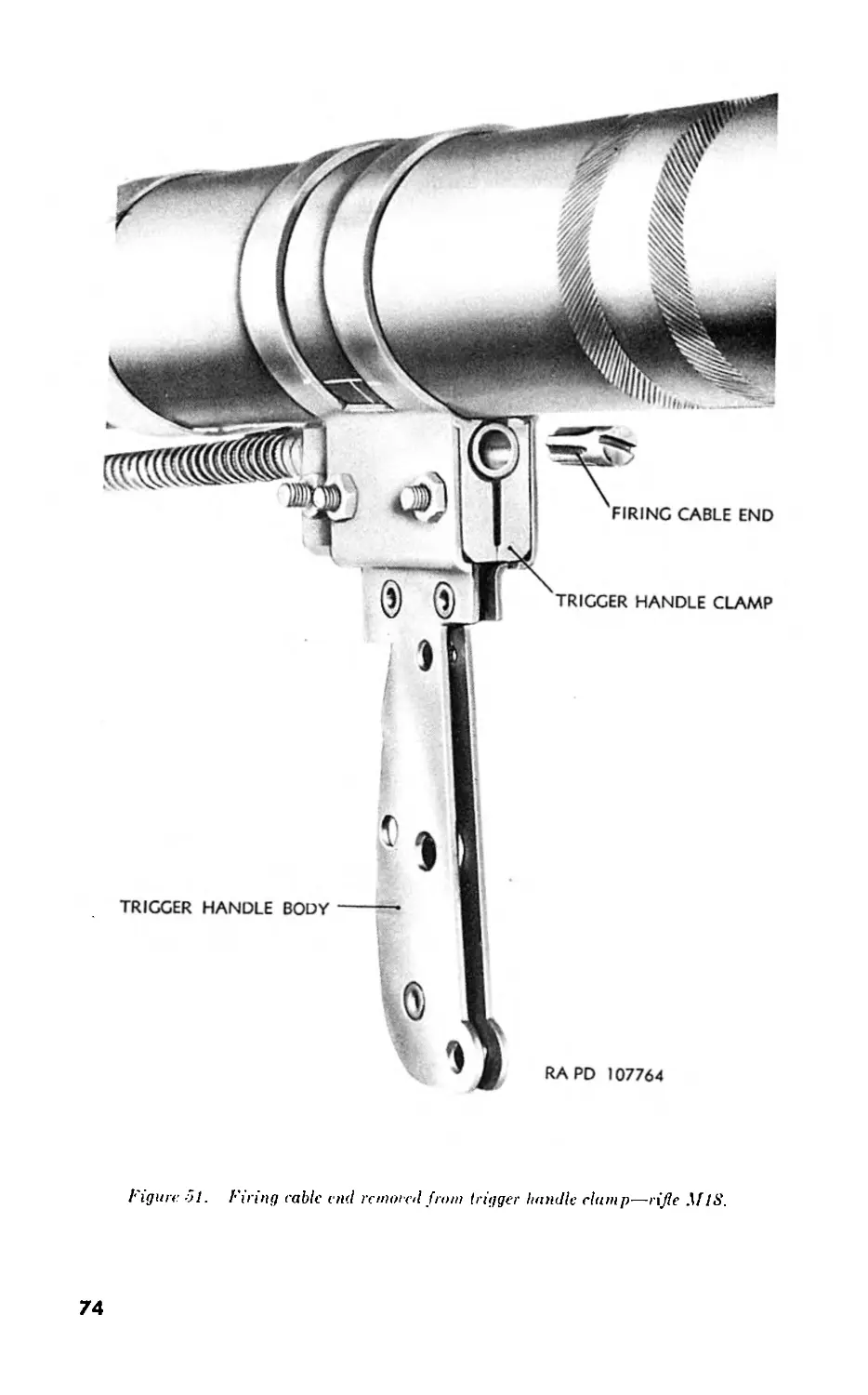
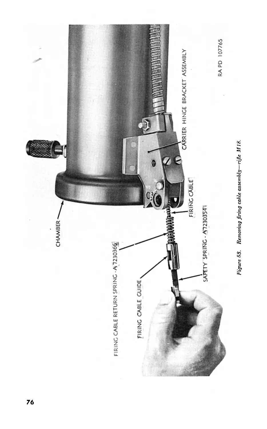
is entrusted only Io those individuals whose official duties
require such knowledge or possession. (See also AR 360—5.)
DEP^^rME^T 0F
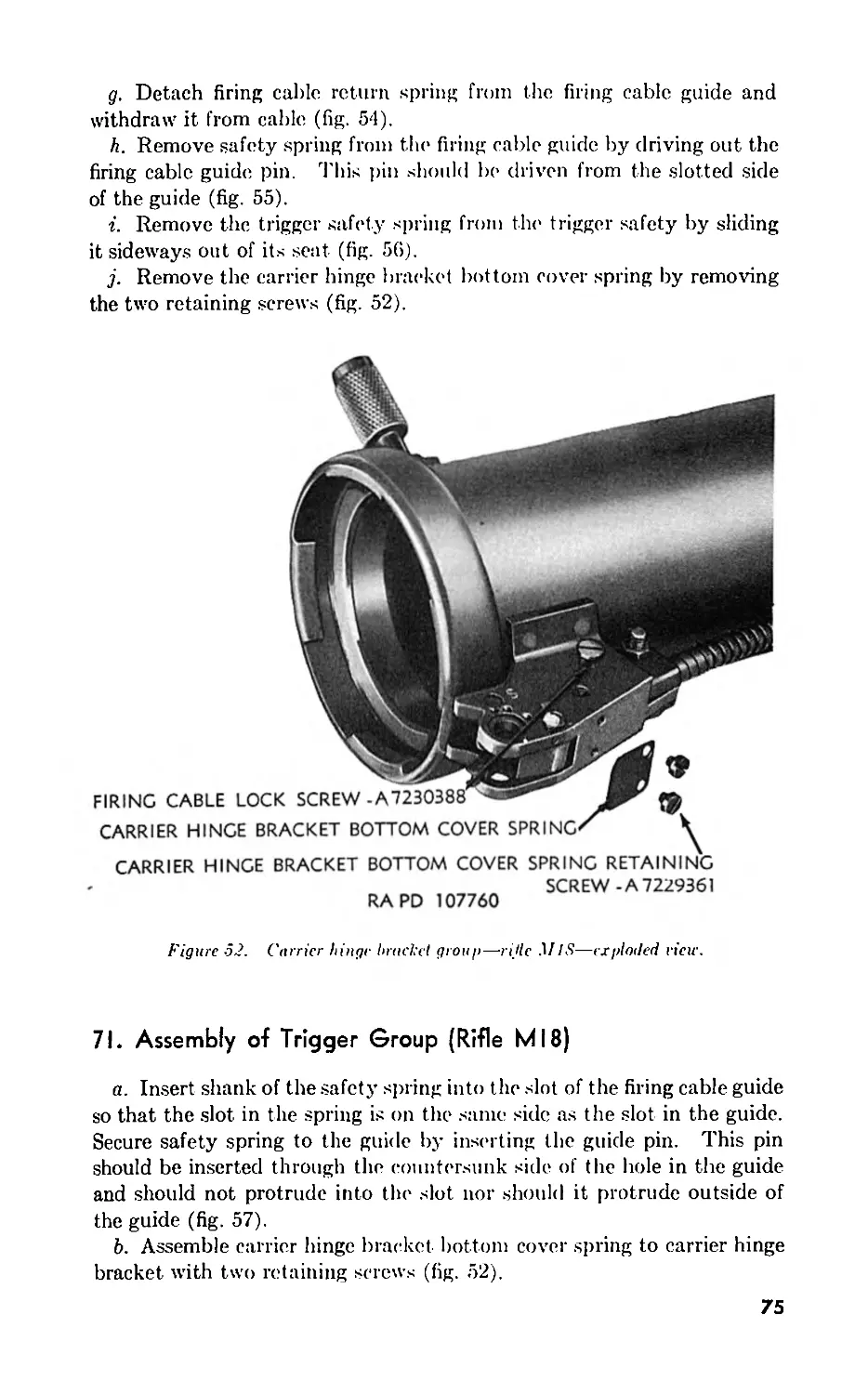
MjRCll 1949
DEPARTMENT OF THE ARMY TECHNICAL MANUAL
TM 9-314
This manual supersedes TM D-304, 25 January 1545: 7’.V .9-5/4, S January 154'': and TH 5-314-1,
6 July Ю45. 7’Ats manual also supersedes TH ORD 3^7, J March !54f so far as it pertains to thts manual:
however, this technical bulletin remains in force until incorporated in all other affected technical manuals or
specifically rescinded.
57-mm RIFLES
T15E13 AND M18
75-mm RIFLES
T21 AND M20 (T25)
DEPARTMENT OF THE ARMY
MARCH 1949
RESTRICTED. DISSEMINATION OF RESTRICTED MATTER.—No
person is entitled solely by virtue of his grade or position to
knowledge or possession of classified matter. Such matter
is entrusted only to those individuals whose official duties
require such knowledge or possession. (See also AR 380—5.)
United Stales Corernntent Printing Of.ee
tfaskin^on : I’W
DEPARTMENT OF THE ARMY
Washington 25, D. C. 22 March 1.949
TM 9-314, 57-mm Rifles T15E13 and M18; 75-mm Rifles T21 and
M20 (T25), is published for the information and guidance of all concerned.
Information in this manual is correct as of 1 September 1948.
AG3OO.7 (19 Oct. 48.)]
By order of the Secretary of the Army:
Official:
EDWARD F. WITSELL
Major General
The Adjutant General
OMAR N. BRADLEY
Chief of Staff, United States Army
Distribution:
Army:
Tech Sv (2); Arm & Sv Bd (1); AFF (2); OS Maj Coind (10);
Base Comd (2); MDW (3); A (ZI) (18), (Overseas) (3); CHQ
(2); D (2); FC (1); USMA (2); Sch (5); Gen Dep (1); Tng
Ctr (2); PE (Ord 0) (5); PG 9 (3); Ars 9 (3); Dist 9 (3); One
(1) copy to each of the following T/O & E’s: 2-13; 2-25; 2-27;
6-218T; 7-3; 7-11; 7-15; 7-17; 7-18; 7-27; 7-31T; 7-37T;
7-51T; 7-55T; 7-57T; 9-7; 9-9; 9-12; 9-57; 9-65; 9-67; 9-76;
9-315; 9-316; 9-318; SPECIAL DISTRIBUTION.
Air Force:
USAF (5).
For explanation of distribution formula see TM 38-405.
ii
CONTENTS
PART ONE
57-mm RIFLES TI5EI3 AND MI8
CHAPTER Section 1. INTRODUCTION. 1. General ... . 11. Description and data Paragraphs 1-2 . 3-6 1 6
CHAPTER Section 2. OPERATING INSTRUCTIONS. 1. General... .. 7 9
II. Service upon receipt of materiel ...... . 8-16 9
III. Controls . 17-21 13
IV. Operation under normal conditions .. . 22-31 17
Г. Operation under unusual conditions.. . 32-36 36
17. Demolition to prevent enemy use ... . 37-38 37
CHAPTER Section 3. MAINTENANCE INSTRUCTIONS. I. General. 39 39
11. Organizational spare parts, tools, ami equipment. . 40-41 39
III. Lubrication . 42-43 41
117. Preventive maintenance service......... . 44-48 45
Г. Malfunctions and corrections ... . 49-53 19
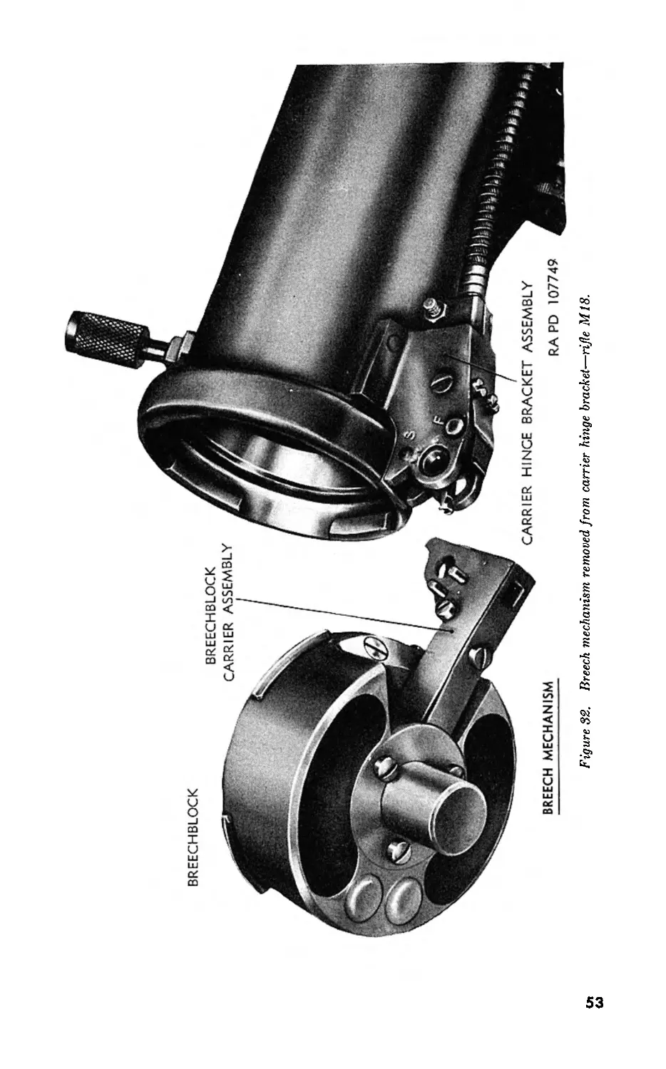
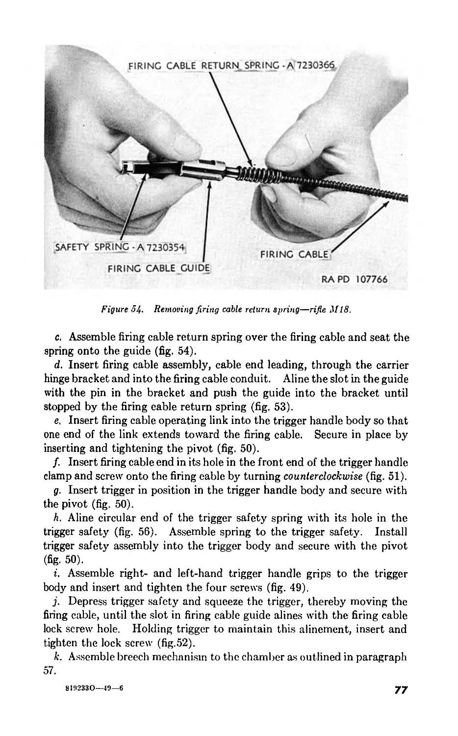
Г/. Breech mechanism (rifle M18) ... . 54-60 50
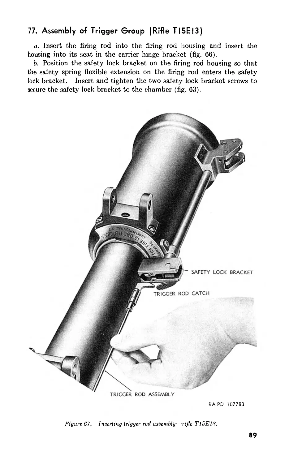
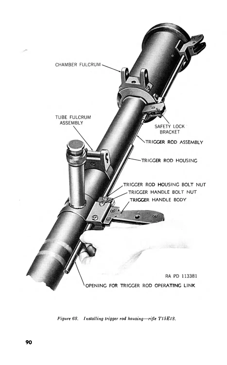
VII. Breech mechanism (rifle T15E13) . 61-67 66
I 'III. Trigger group (rifle M18) . 68-73 71
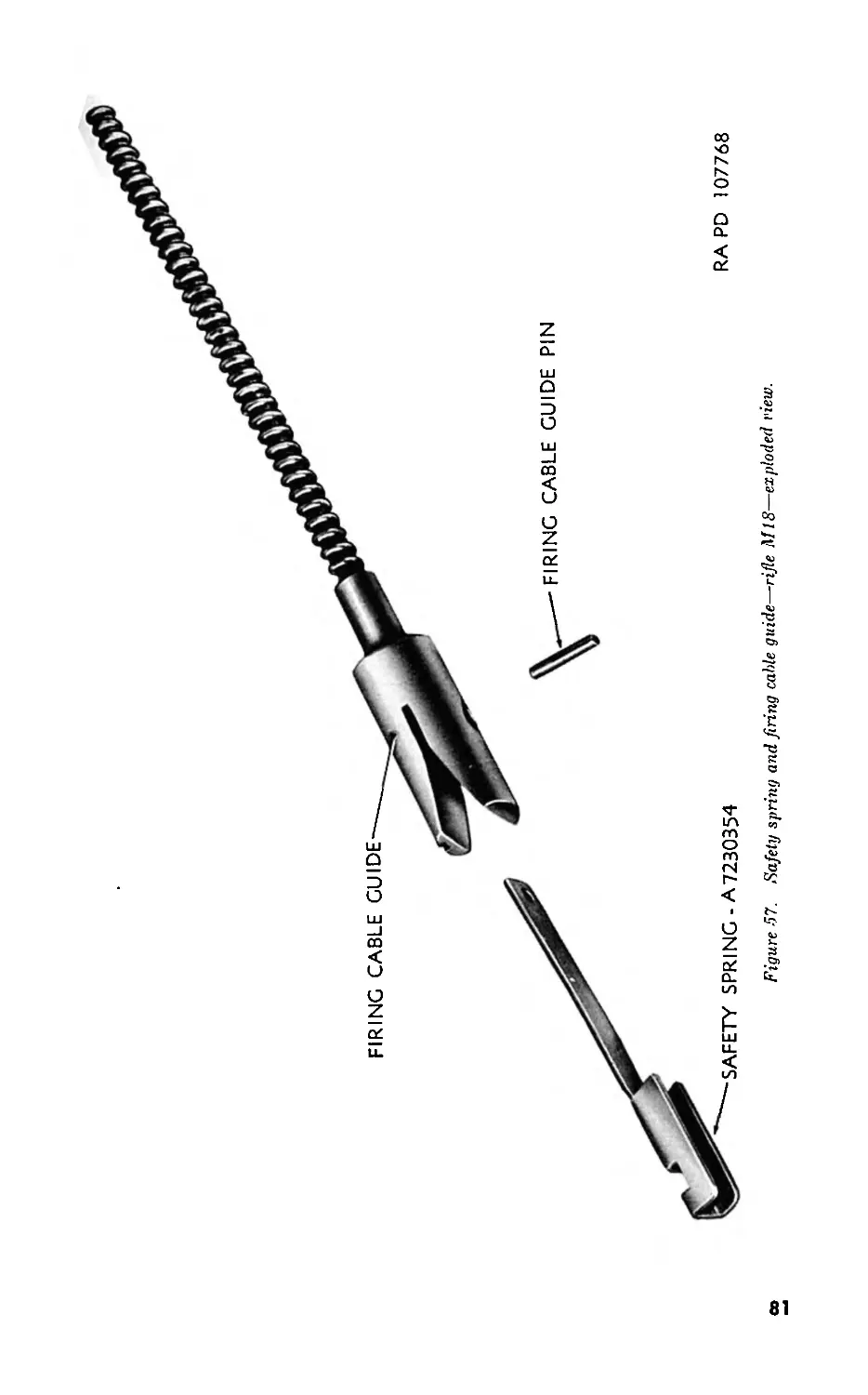
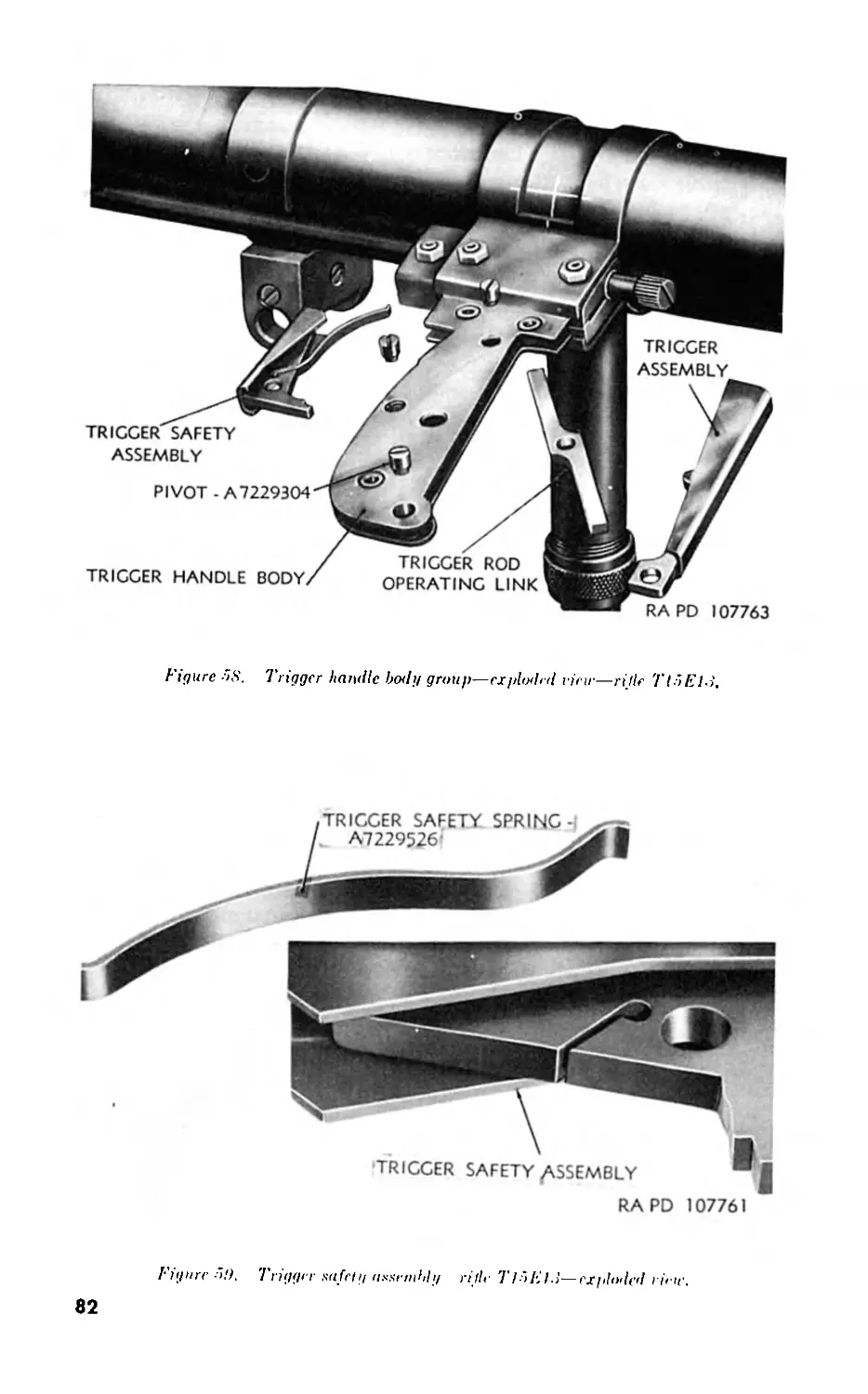
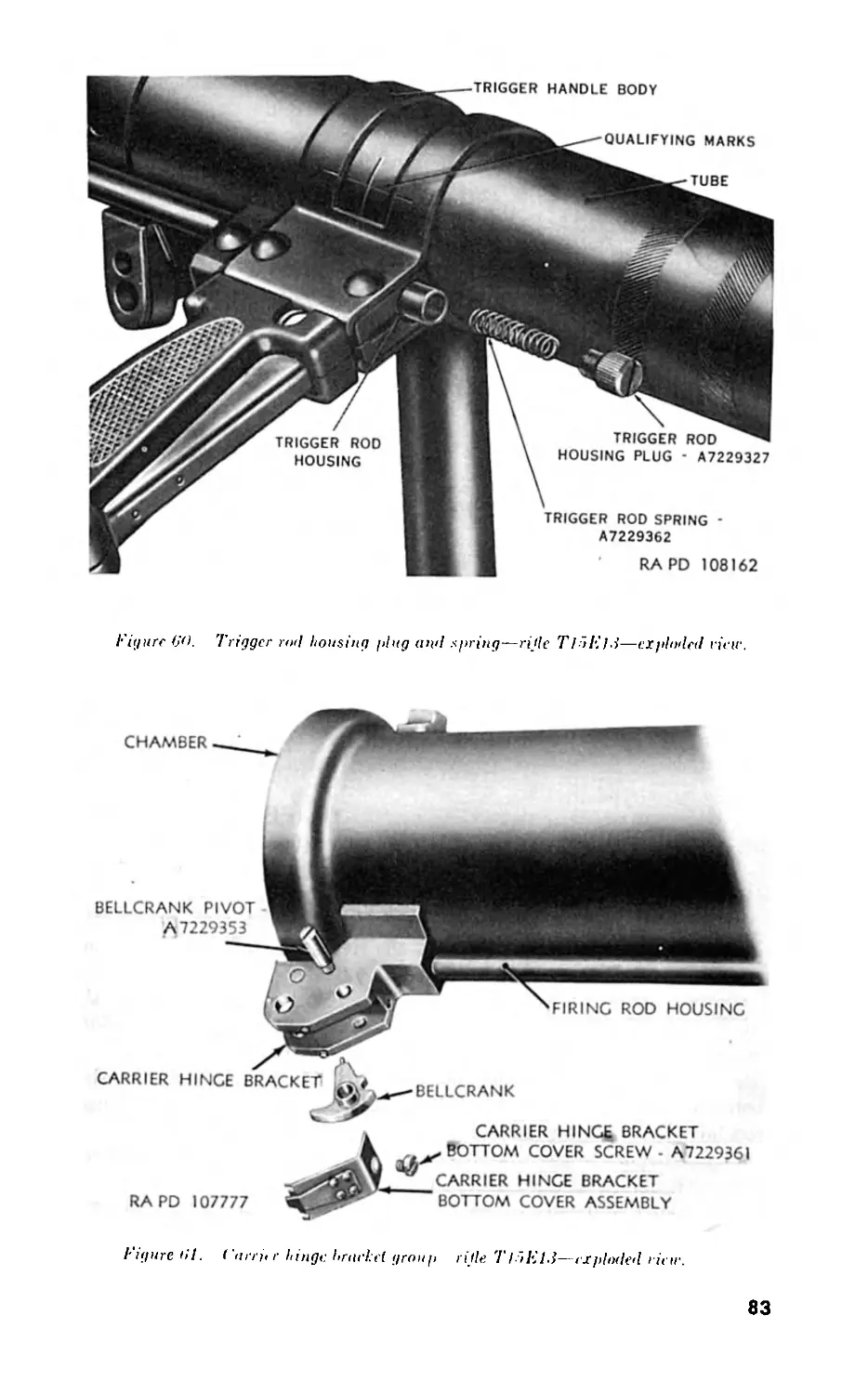
IX. Trigger group (rifle T15E13) . 74-79 80
X Barrel group. . . 80-84 92
CHAPTER Section 4. AUXILIARY EQUIPMENT. /. General 85 95
II. Ammunition . 86-94 95
III. Sighting and fire control equipment . 95-99 101
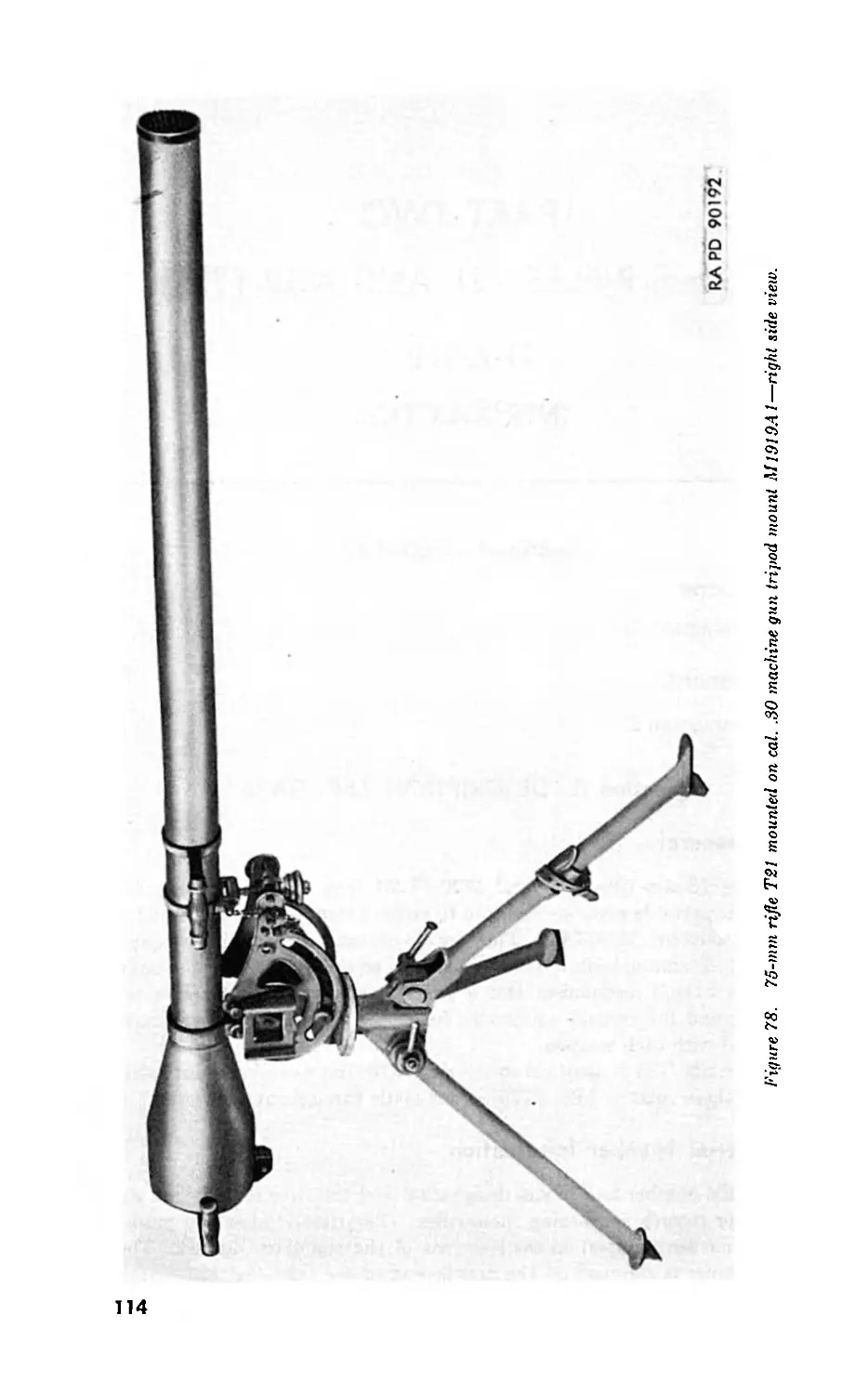
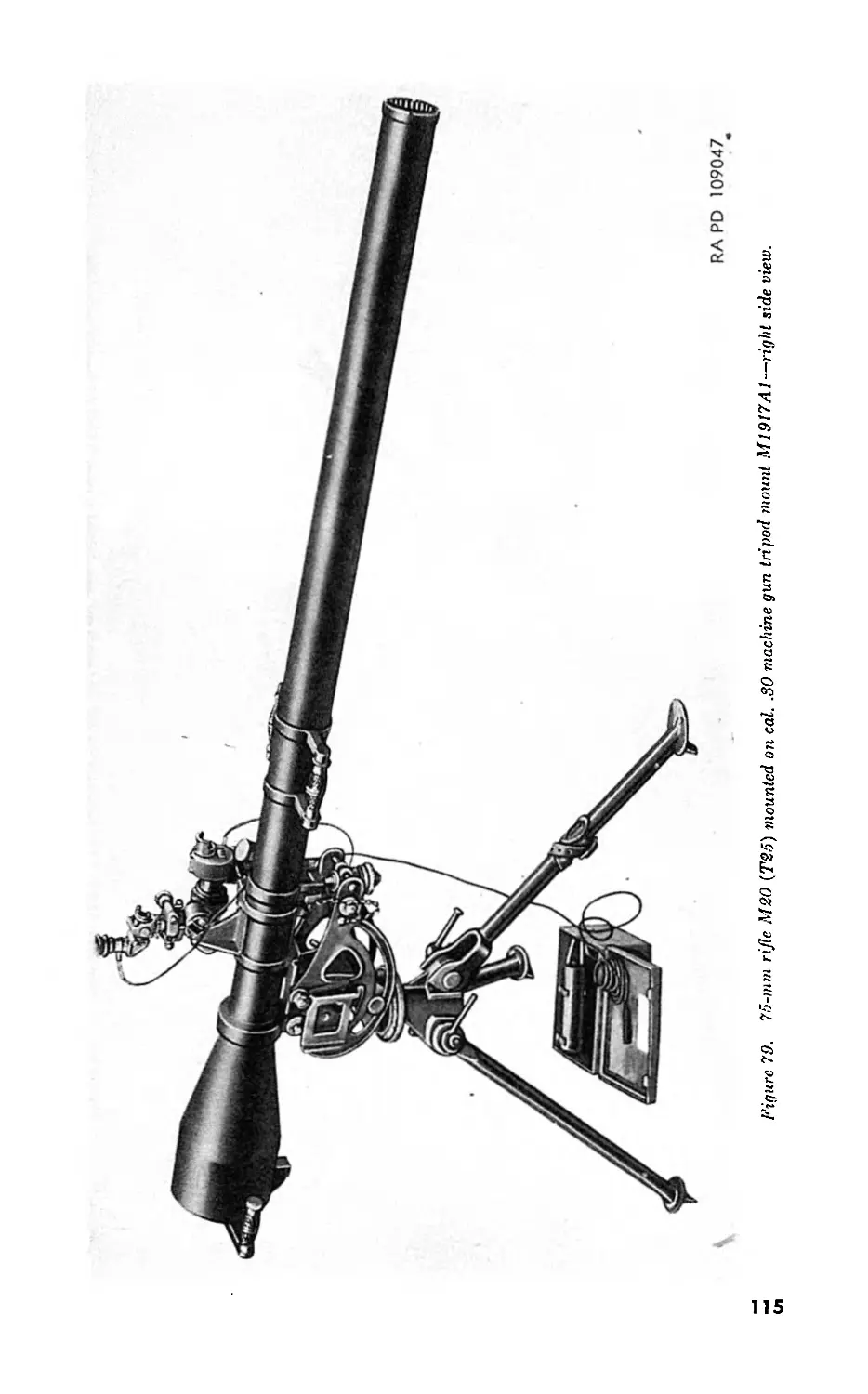
PART TWO
75-mm RIFLES T2I AND M20 (T25)
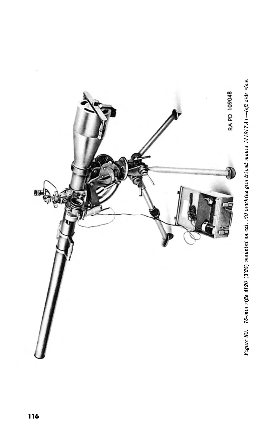
CHAPTER 5. INTRODUCTION.
Seclion I. General_____________________________________ 100-101 113
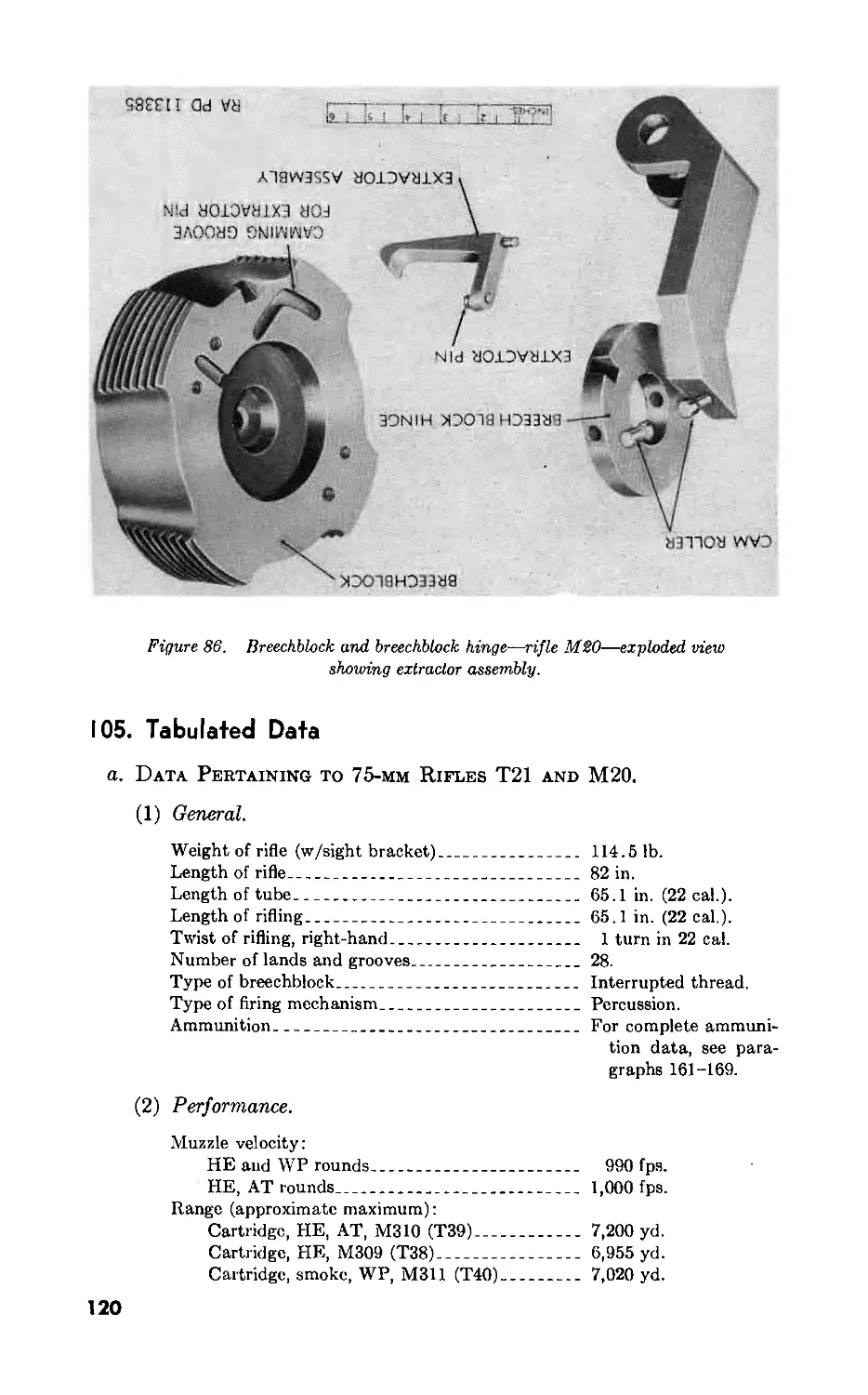
//. Description and data_________________________ 102-105 113
CHAPTER 6. OPERATING INSTRUCTIONS.
Section I. General__________________________________________ 106 123
ll. Service upon receipt of mat6riel______________107-I0!) 123
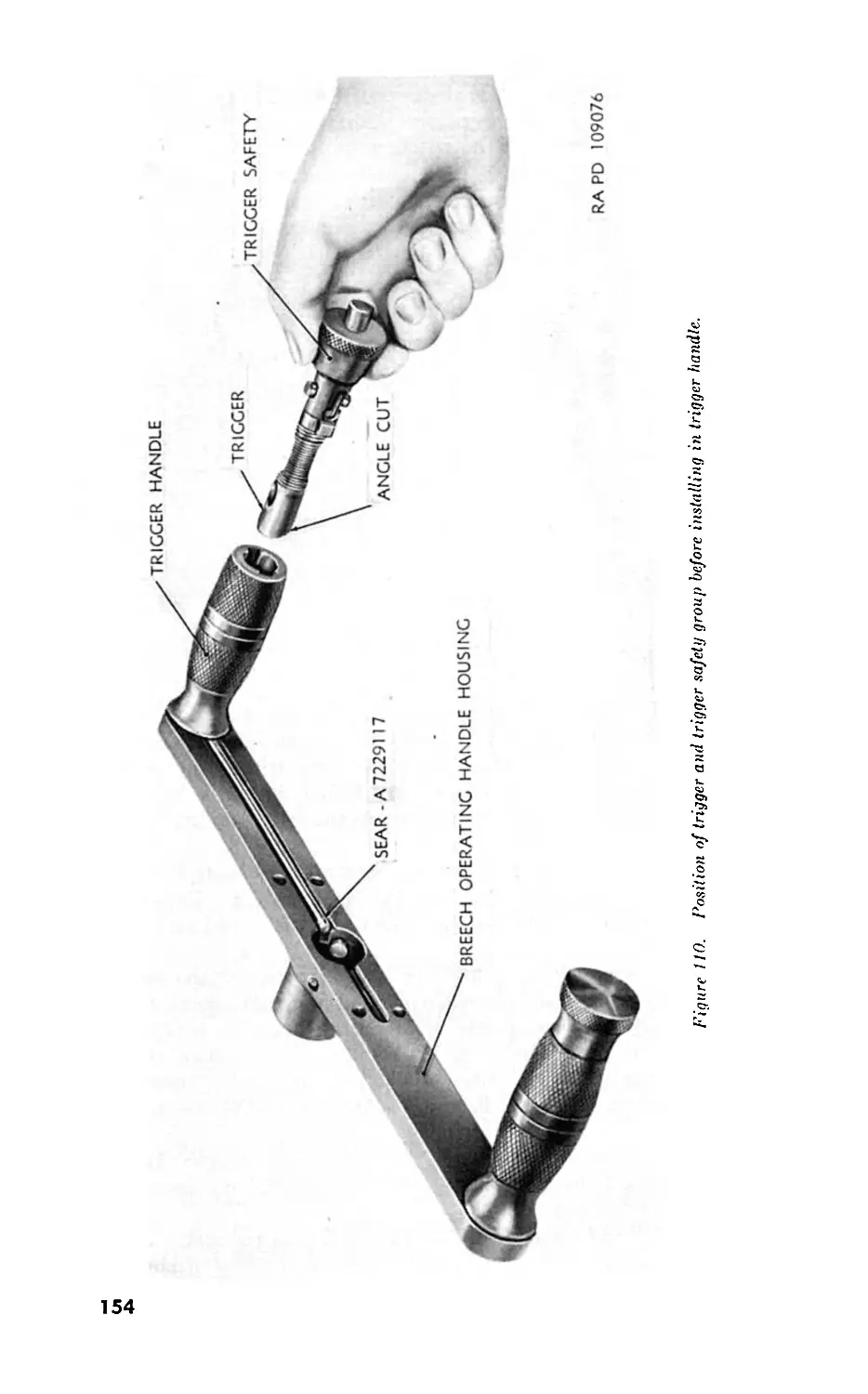
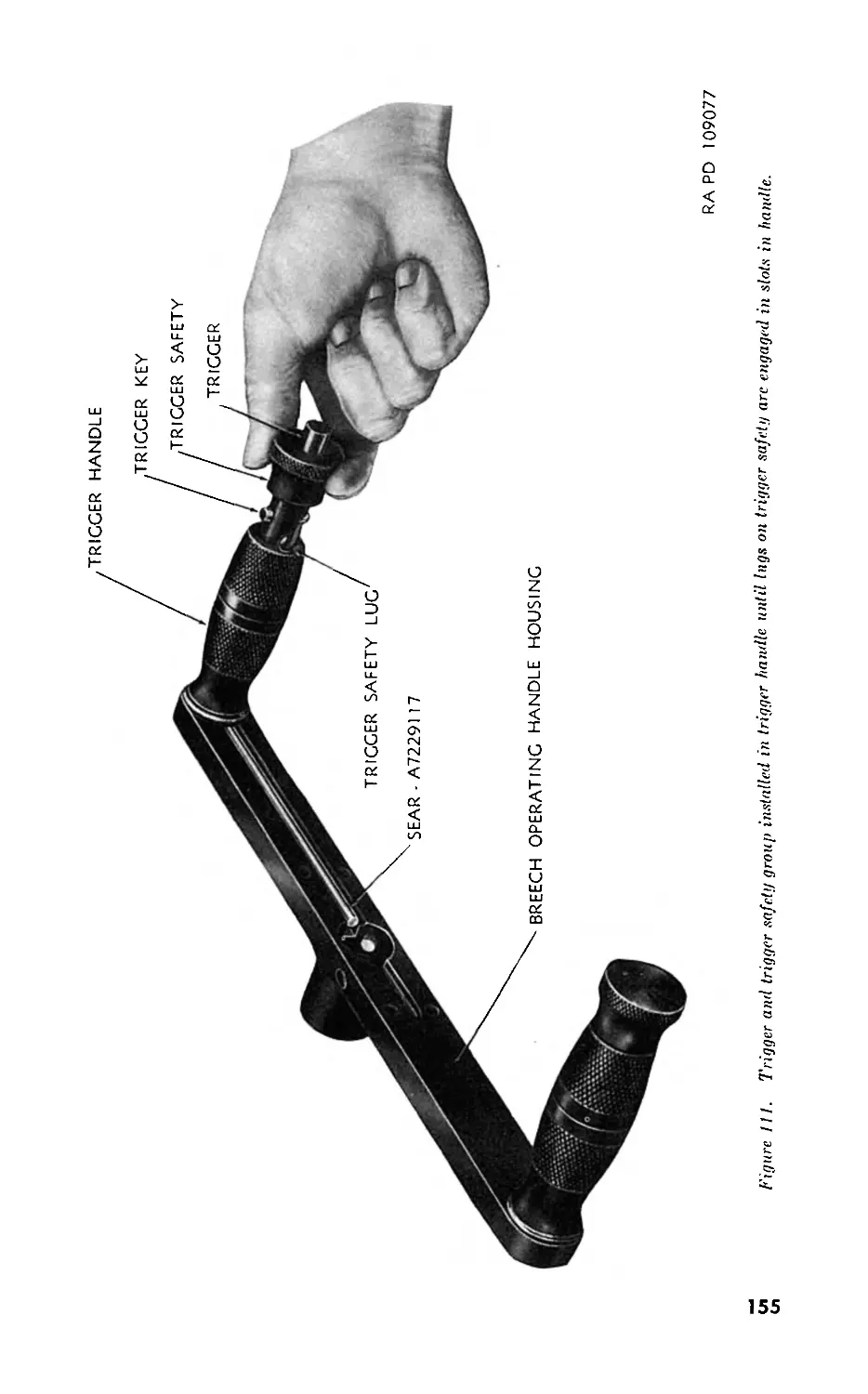
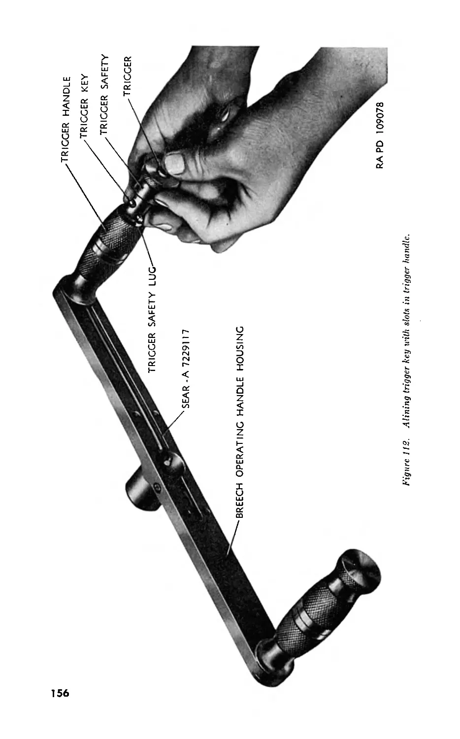
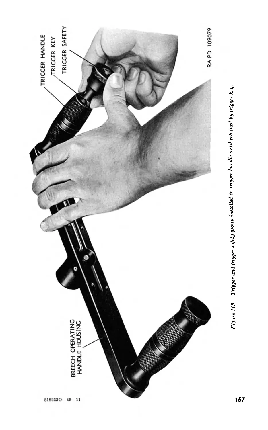
III. Controls_____________________________________ 110-112 121
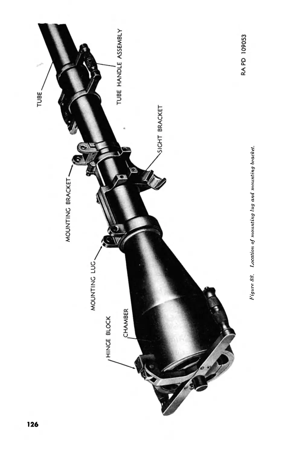
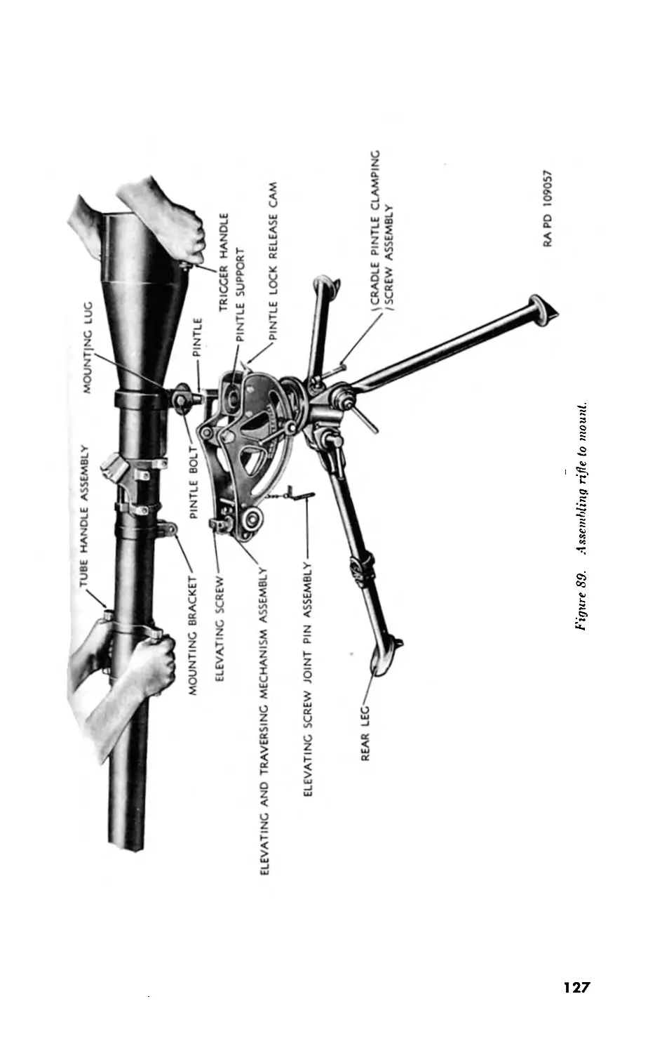
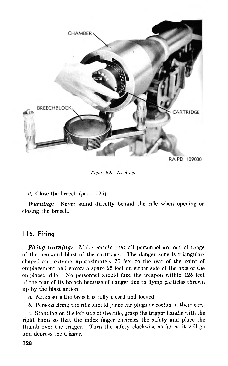
IV. Operation under normal conditions______________113-118 125
V. Operation under unusual conditions_______________ 119 130
VI. Demolition to prevent enemy use___________________ 120 130
Hi
CHAPTER 7. MAINTENANCE INSTRUCTIONS.
Section I. General .. . 121 131
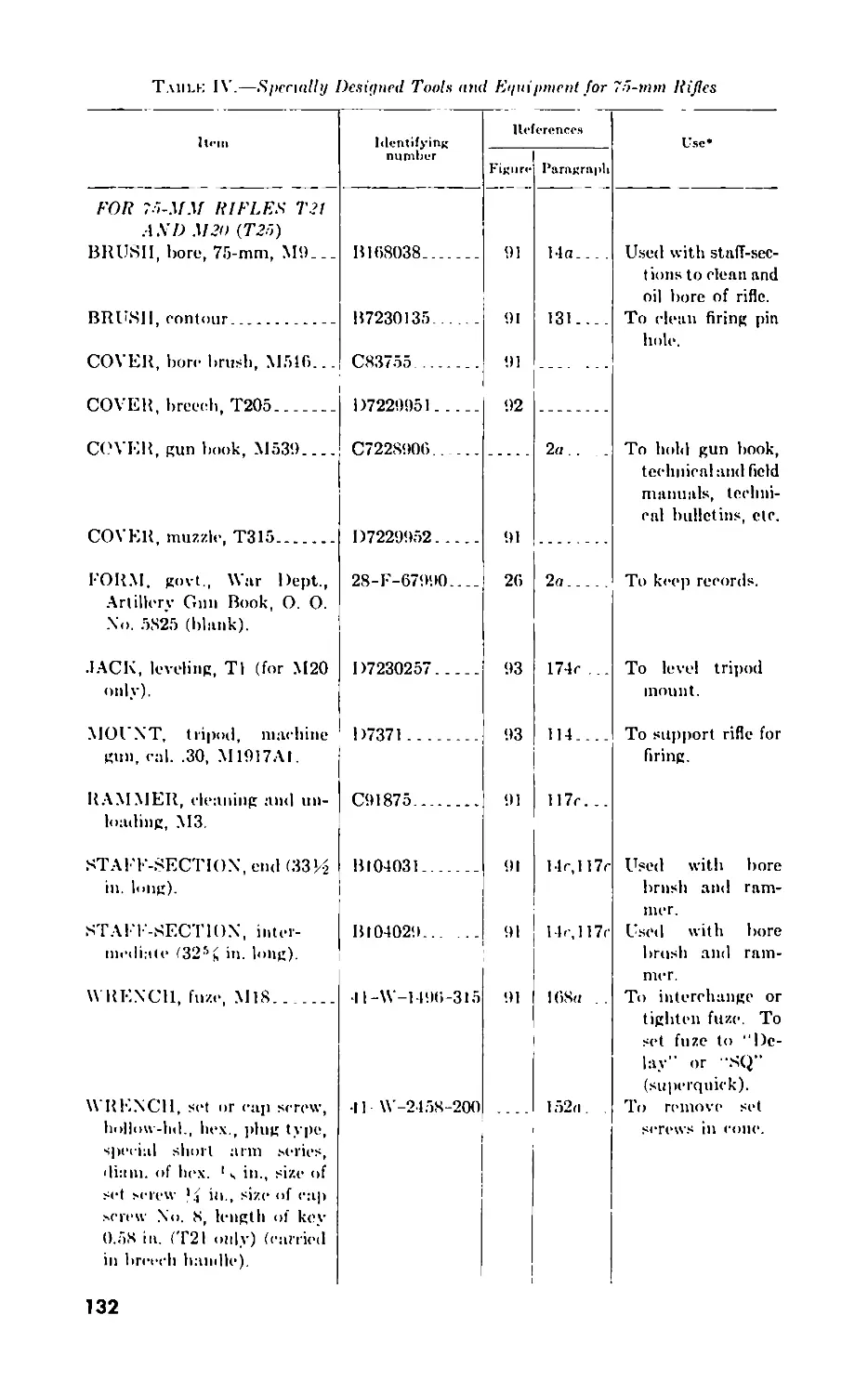
II. Organizational spare parts, tools, and equipment. 122-123 131
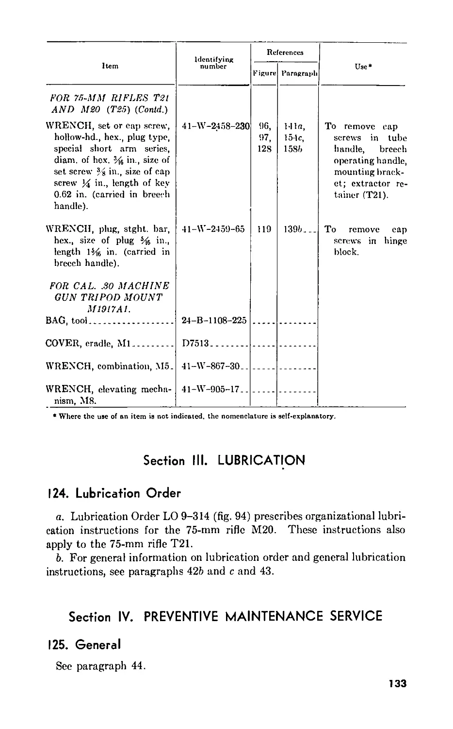
Ill. Luhricat ion _ 121 133
IV. Preventive maintenance service 125-129 133
Г. Malfunctions and corrections .130-136 138
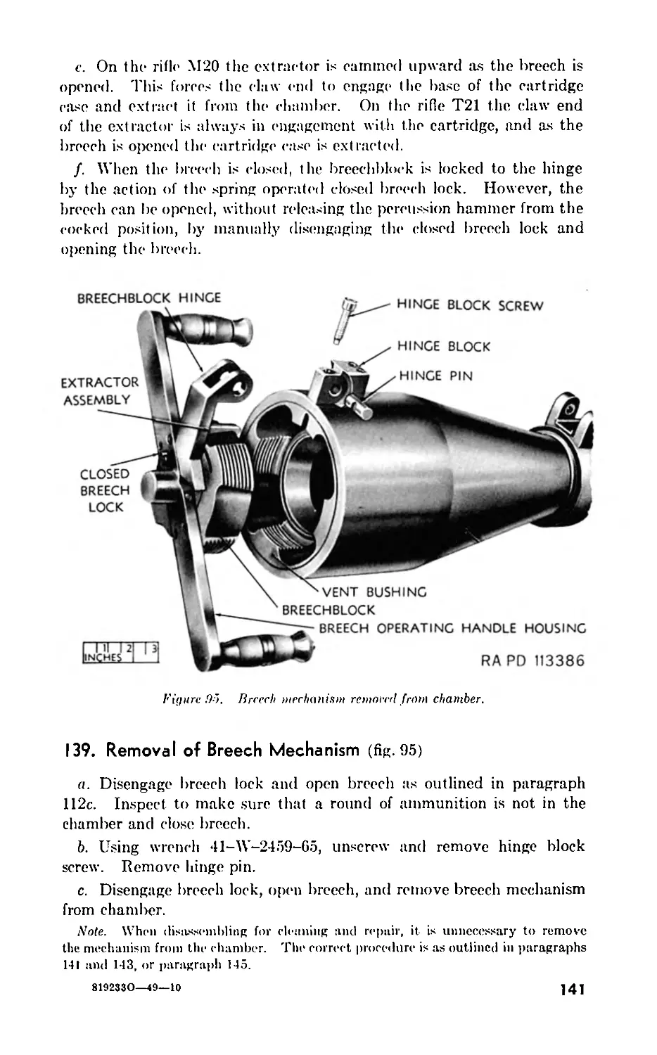
VI. Breech mechanism 137-119 no
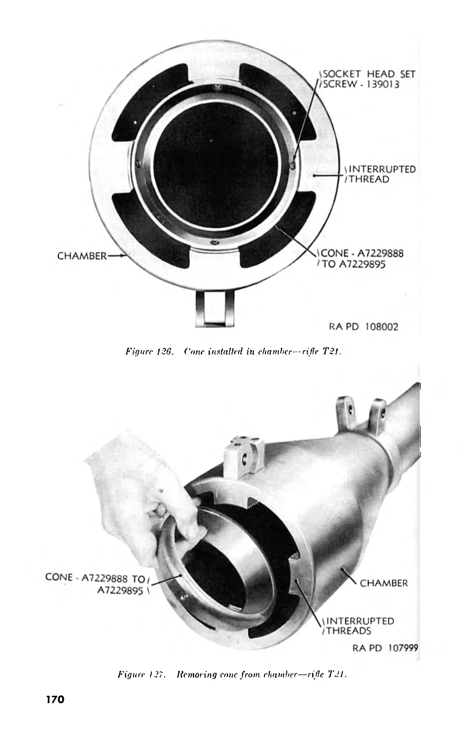
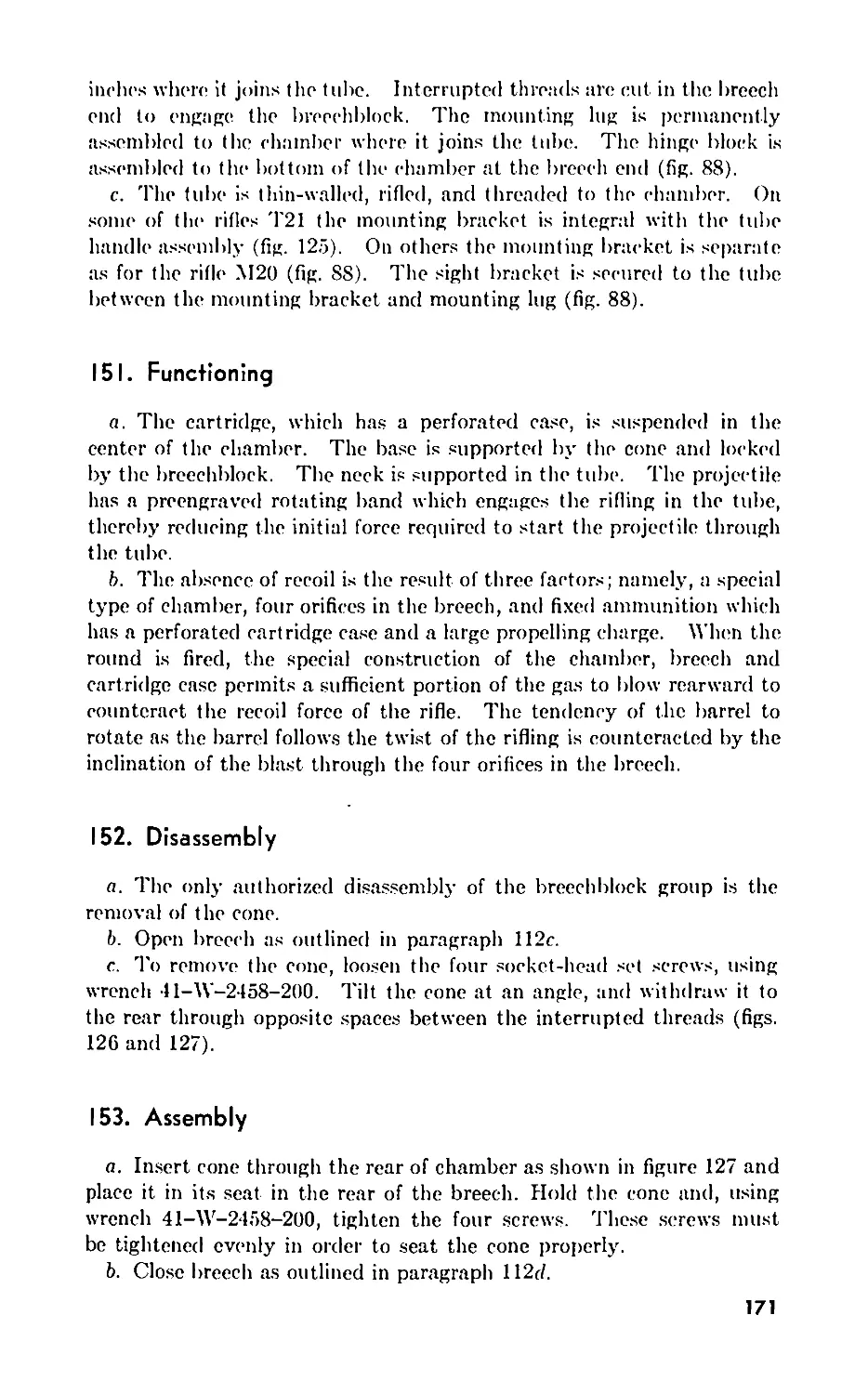
VII. Barrel group (rifle T2I) ... . 150 155 169
VIII. Barrel group (rifle M20) .156-159 173
CHAPTER 8. AUXILIARY EQUIPMENT.
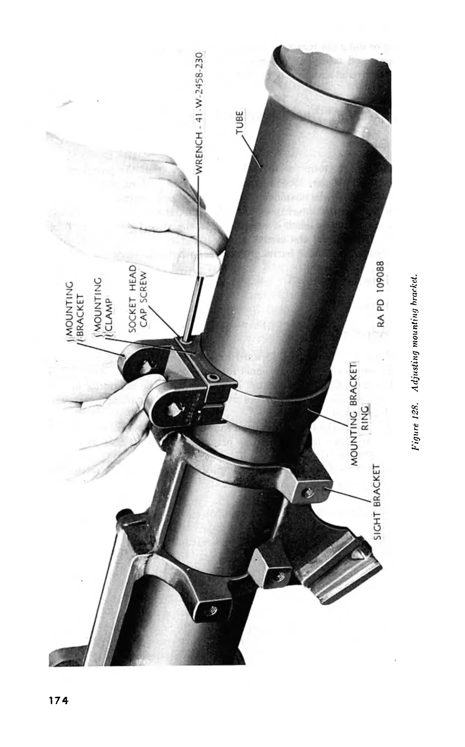
Section I. General __ . 160 175
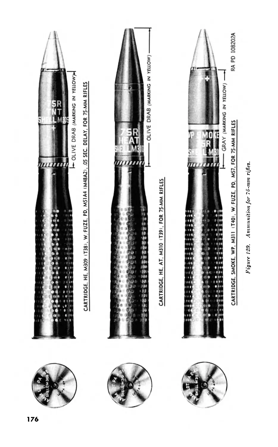
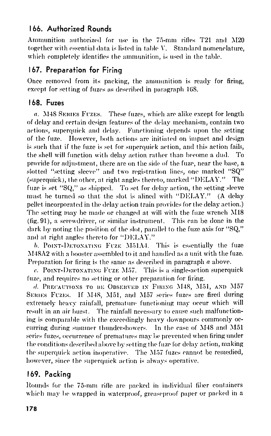
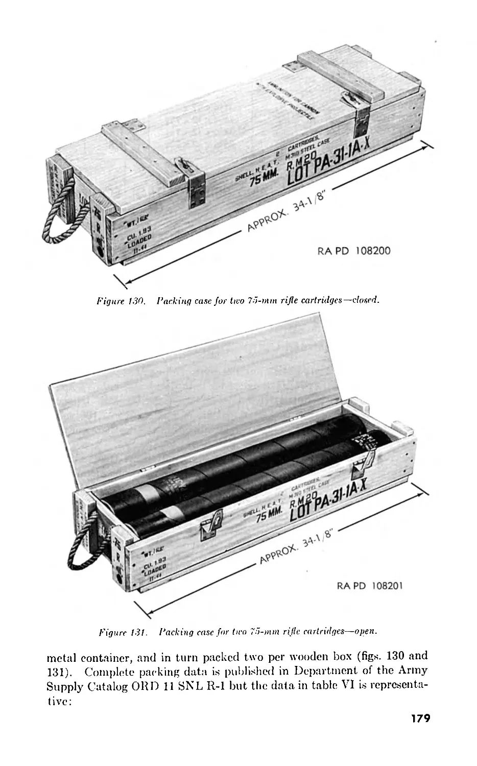
II. Ammunition 161-169 175
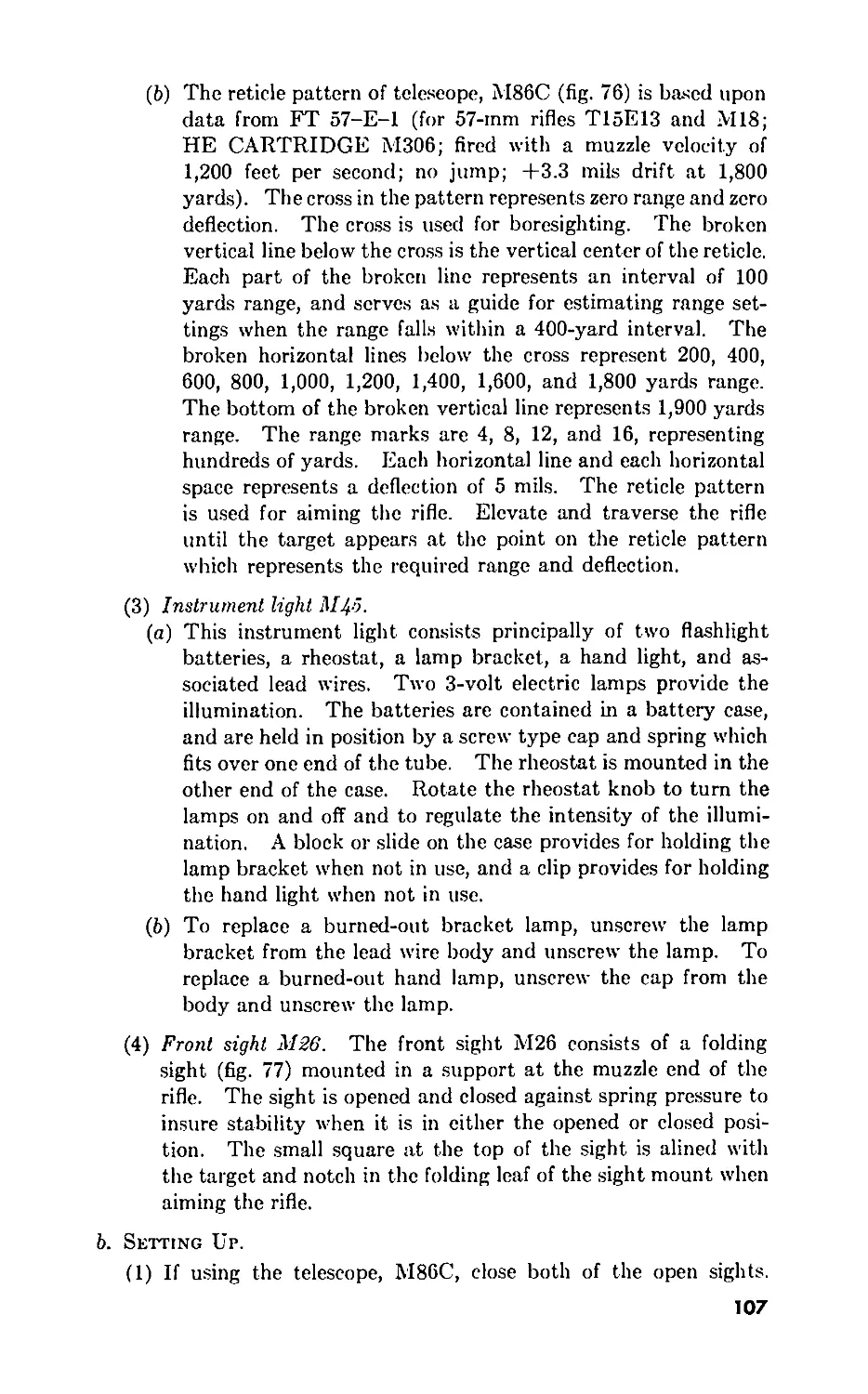
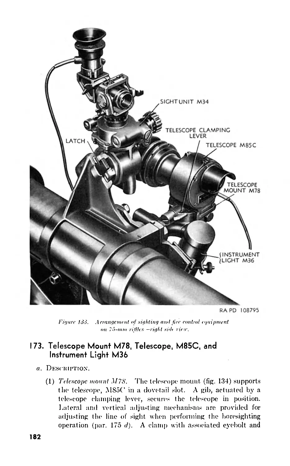
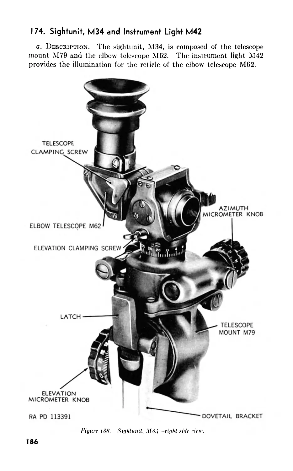
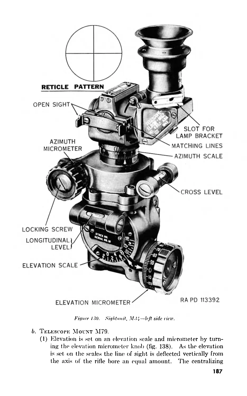
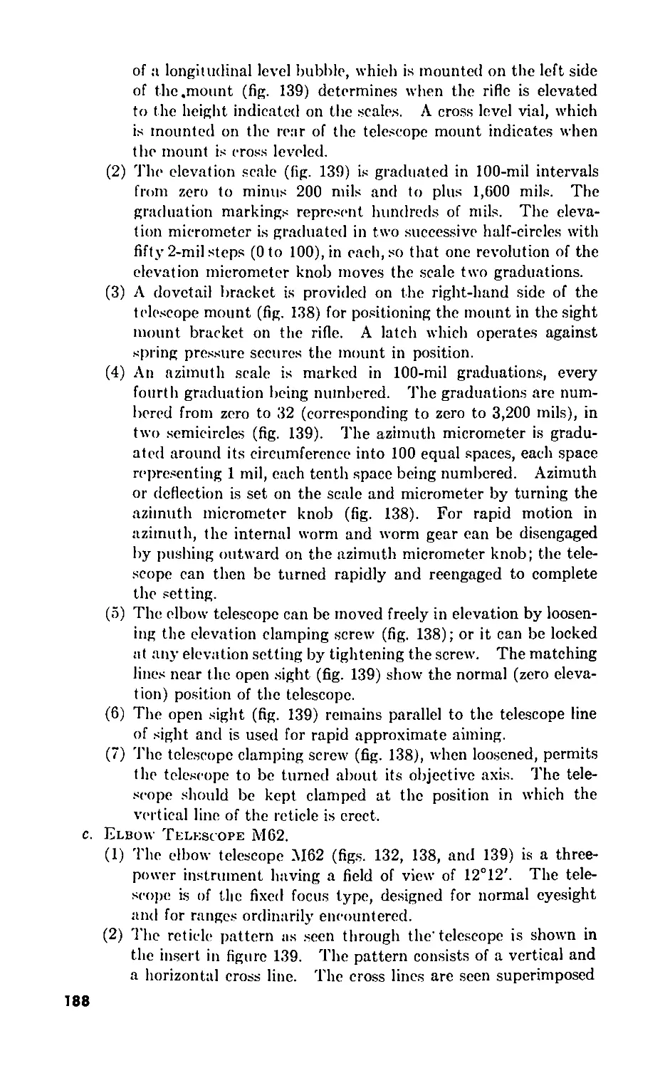
III. Sighting and fire control equipment . 170-175 180
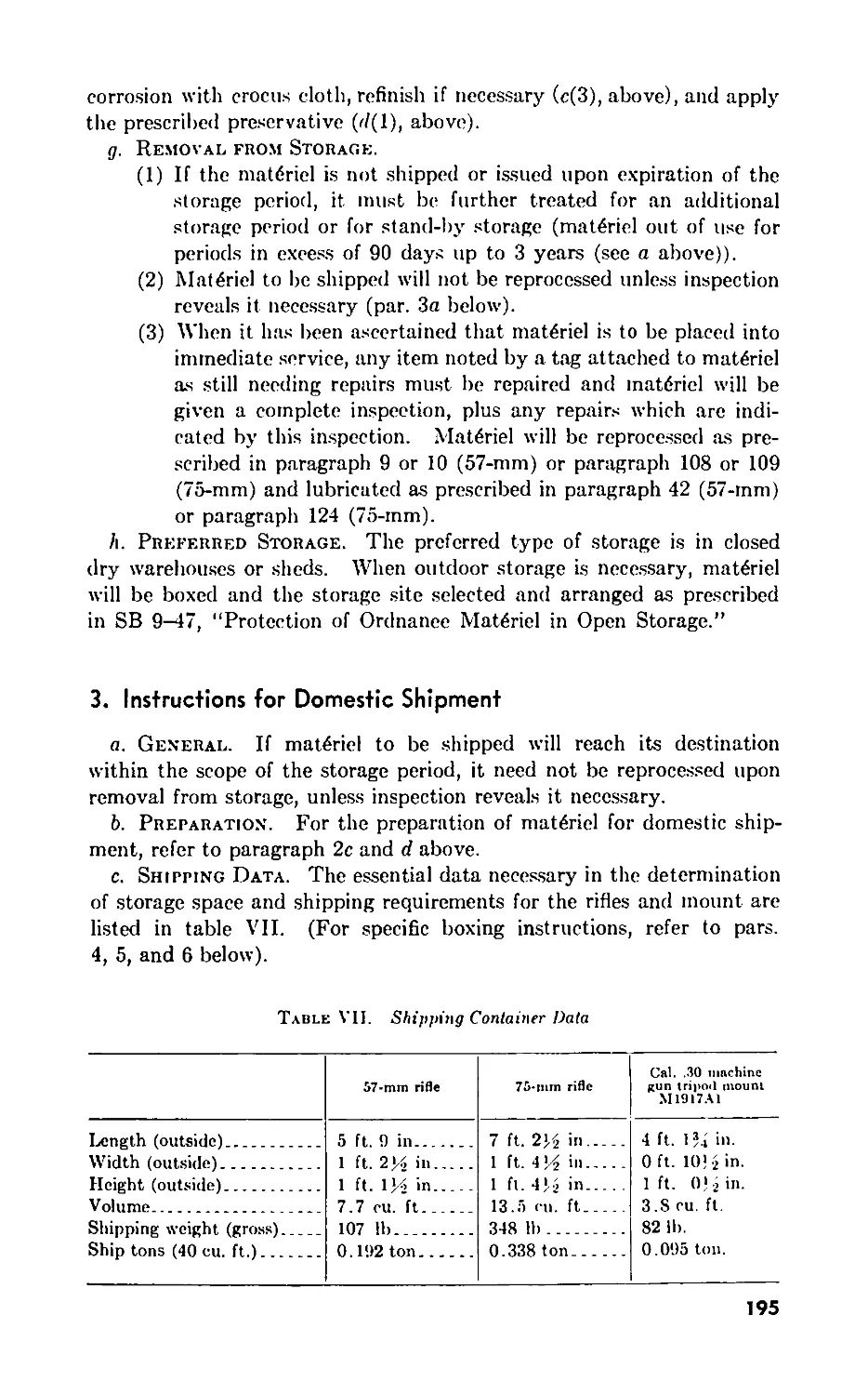
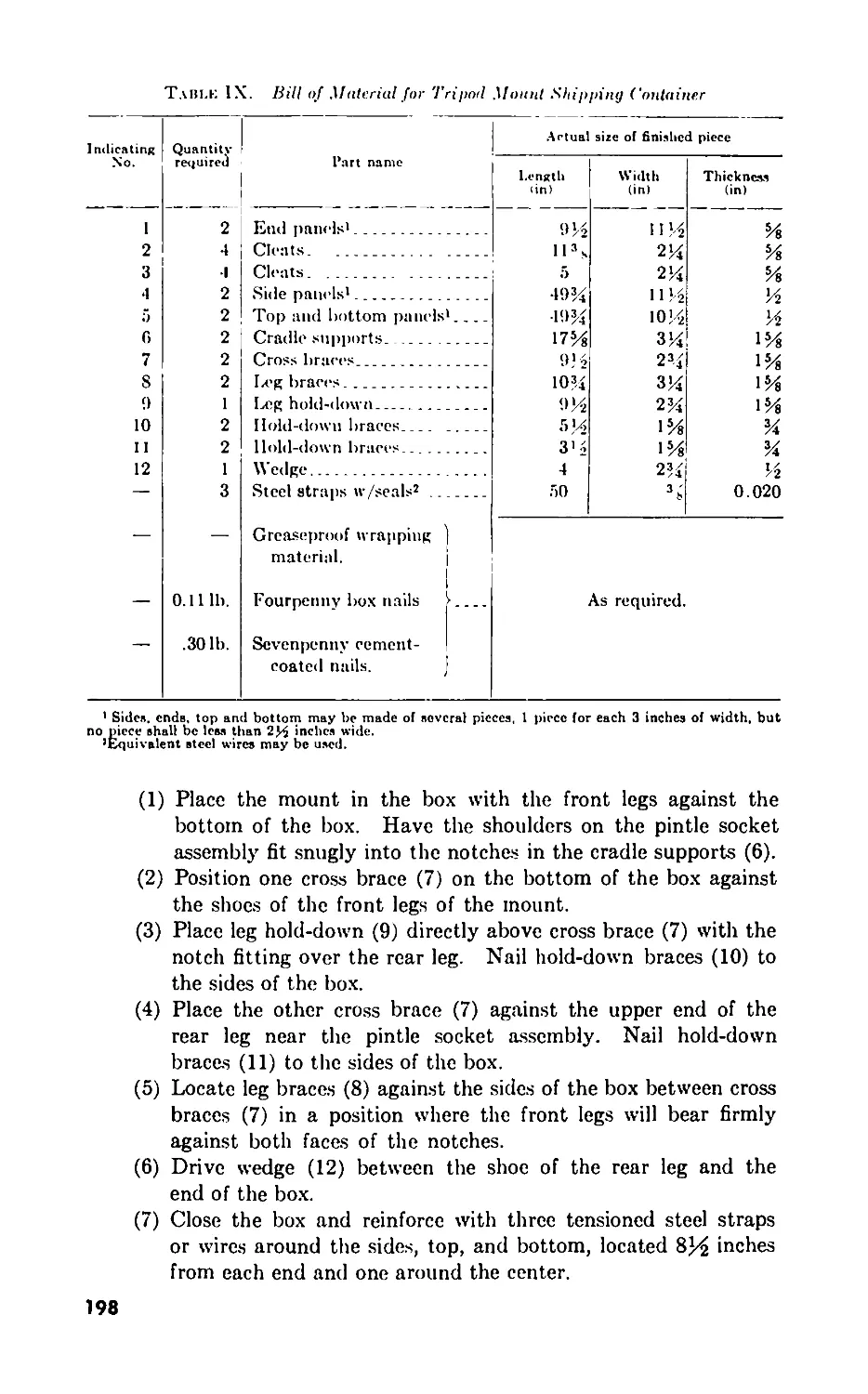
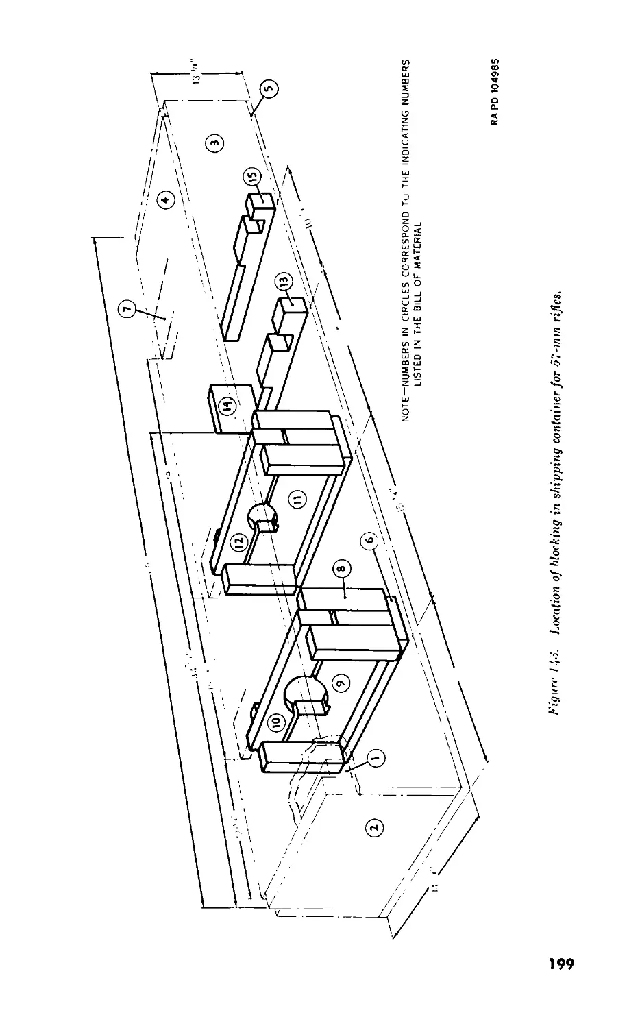
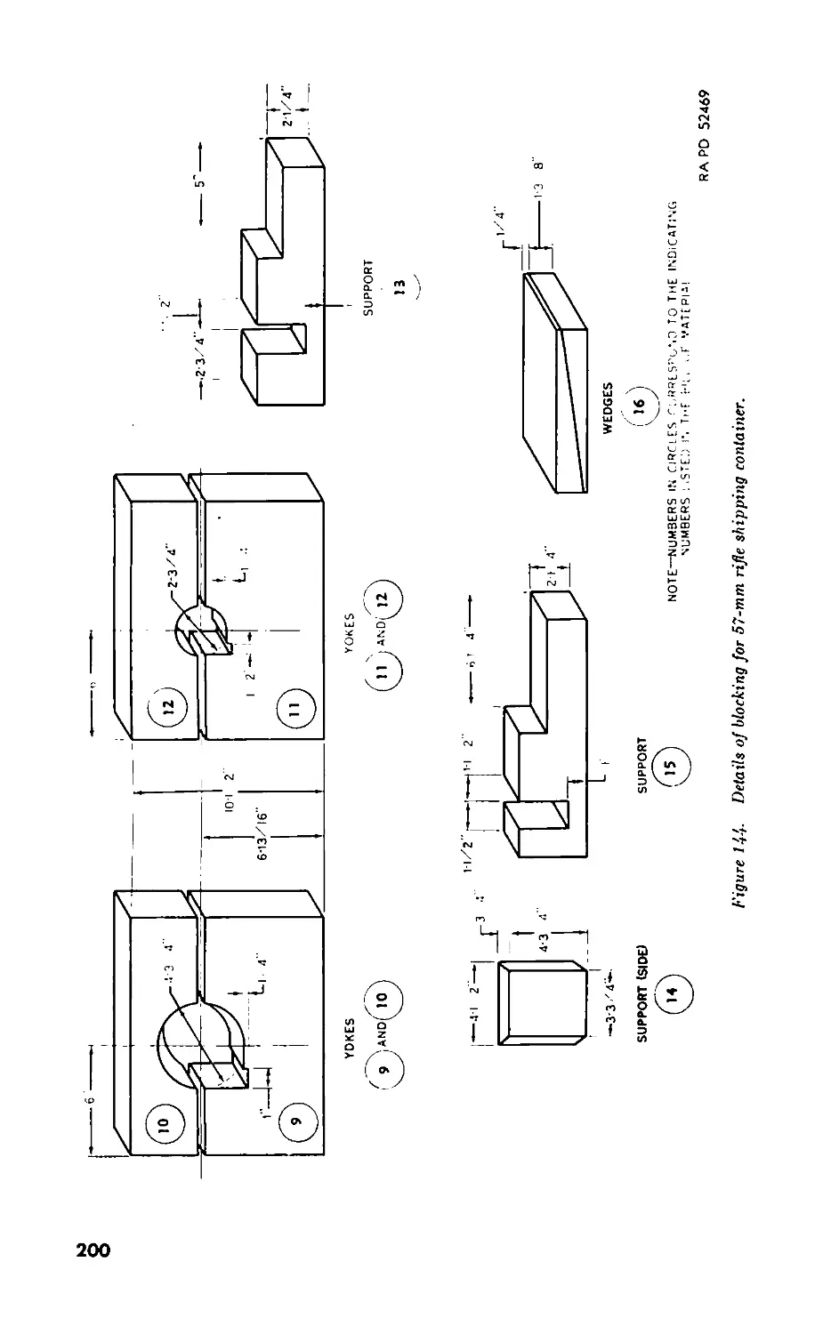
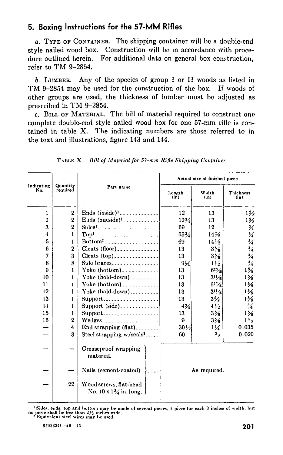
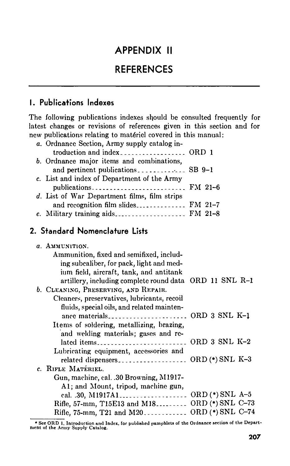
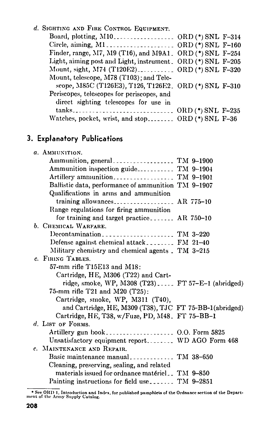
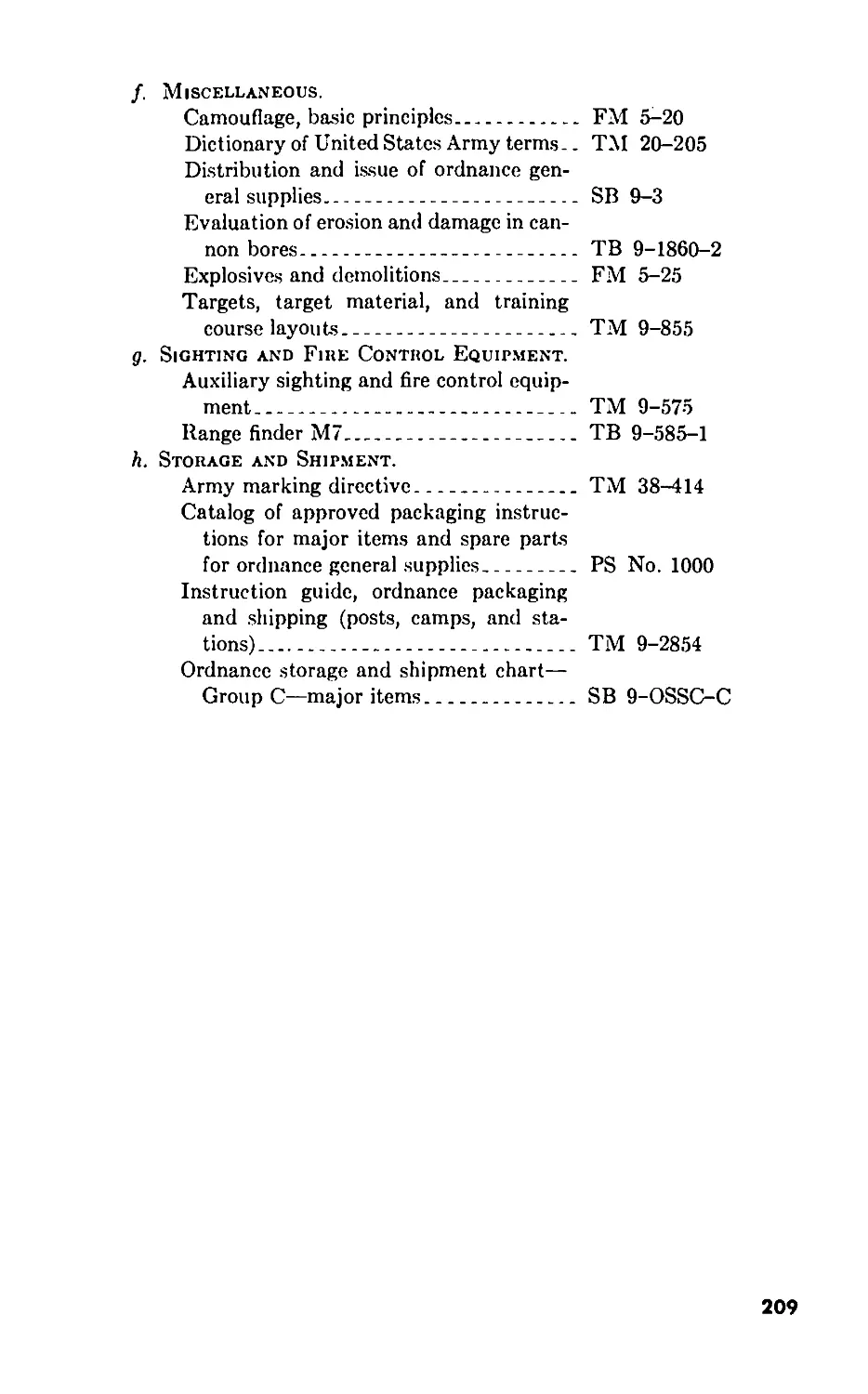
APPENDIX I. STORAGE AND SHIPMENT____________________________ 193
II. REFERENCES____________________________________ 207
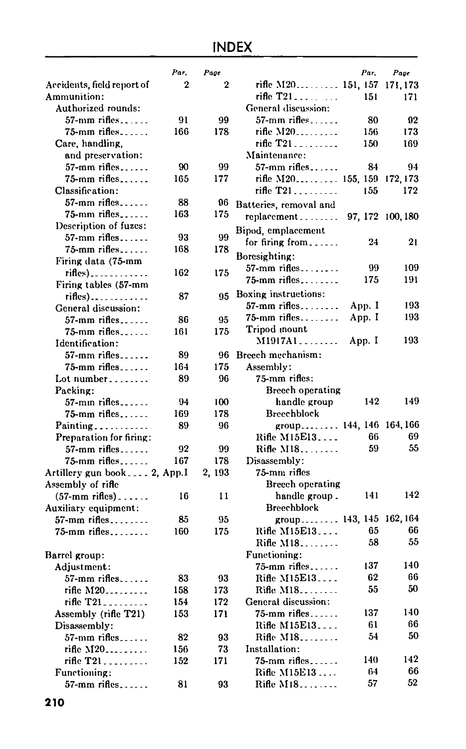
INDEX__________________________________________________________ 210
IV
RESTRICTED
This manual supersedes TM 9-304, 25 January 1945; TM 9-314, 8 January 1945;
and ТВ 9-314-1, 6 July 1945. This manual also supersedes ТВ ORD 347, 3 March
191f7, so far as it pertains to this manual; however, this technical bulletin remains in
force until incorporated in all other affected technical manuals or specifically rescinded.
PART ONE
57-mm RIFLES TI5EI3 AND MI8
CHAPTER I
INTRODUCTION
Section I. GENERAL
I. Scope
a. This manual is published for the information of the using arm and
services. It contains technical information required for the identification,
use, and care of the 57-mm rifles T15E13 and M18 and 75-mm rifles T21
and M20 (T25), ammunition and equipment.
b. The 57-mm rifles T15E13 and M18 are covered in part one. The
75-mm rifles T21 and M20 (T25) are covered in part two. Data for the
75-mm rifles which also applies to the 57-mm rifles are covered in part
one with an appropriate reference in part two. Storage and shipment
data for the 57-mm rifles and the 75-mm rifles are covered in the appendix.
c. In all cases where the nature of the repair, modification, or adjust-
ment is beyond the scope or facilities of the unit, the responsible ordnance
service should be informed so that trained personnel with suitable tools
and equipment may be provided, or proper instructions issued.
d. This manual differs from TM 9-304, 25 January 1945, and TM
9-314, 8 January 1945, as follows:
(1) Adds information on—
(n) 57-mm rifle M18.
(b) 75-mm rifle M20.
(c) Lubrication orders.
1
(2) Revises information on—
(я) Cleaning.
(6) Procedure for demolition.
(c) Preventive maintenance service.
(d) Assembly and disassembly.
(c) Ammunition.
(/) Sighting and fire control equipment.
(</) Storage and shipment.
(3) Deletes reference to 57-mm rifle T15E9.
2. Records
a. Artillery Gun Book
(1) The Artillery Gun Book (O.O. Form 5825) is used to keep an
accurate record of the inat6ricl. The gun book is stored in gun
book cover M539. The book is divided as follows: Record of
assignment; unit commander’s daily gun record; and the in-
spector’s record of examination.
Xotc: Record of assignment data must be removed and destroyed prior to enter-
ing combat.
These records are important for the following reasons:
(a) They inform unit commanders of the condition and service-
ability of the weapons under their jurisdiction.
(6) They serve as the record of use and maintenance of the ma-
teriel and expedite effective maintenance.
(c) They serve as a source of technical data to the Ordnance
Department for the improvement of weapons, and furnish
valuable design data for the development of new weapons.
(2) Complete instructions on how to make entries in the Artillery
Gun Book are contained therein. It is absolutely essential that
the gun book be kept complete and up-to-date, and that the gun book
accompany the materiel al all times regardless of where it may be
sent. In order to facilitate proper maintenance of the rifle and
and its related mat6ricl (i.e., mount and associate fire-control
equipment), and to avoid unnecessary duplication of repairs
and maintenance, the following additional entries in the gun
book are prescribed:
(a) A record of completed army modification work orders. The
record will show the date completed and bear the initial of the
officer or mechanic responsible for completion of the modifica-
tion.
(b) A record of the seasonal changes of lubricant in sufficient
detail to prevent duplication and afford proper identification
by the inspector.
(c) A record of all throat rings and throat blocks used on the 57-mm
rifles T15E13 and M18 or cones used on the 75-mm rifle T21,
their size and the number of rounds fired with each.
2
(d) The estimated accuracy life of the 57-mm rifles is listed in
paragraph 6 and for the 75-min rifles, it is listed in paragraph
105.
(3) The following procedure is prescribed to insure that the Artillery
Gun Book will always accompany mat6riel whenever it is
shipped or transferred from one organization to another:
(a) During transfer or shipment, the gun book will be kept in a
waterproof envelope securely fastened to the materiel with
waterproof tape.
(6) Under one of the wrappings of tape, one end of a small tab
will be inserted reading “Gun Book Here.”
(4) Instructions for making gun book entries and the procedure for
keeping the gun book with the rifle whenever it is shipped or
transferred from one organiztion to another must be followed
strictly. Ordnance maintenance units, base shops, and depots
will insist that the gun book accompany each rifle when it
enters their shop for repairs or maintenance.
(5) If a gun book is lost, it will be replaced at once and all available
data will be entered in the new gun book. Additional copies of
Artillery Gun Book (O.O. Form 5825, Official Stock No.
28-F-67990) may be requisitioned through normal ordnance
supply channels. A gun book which has become separated
from the weapon to which it pertains and for which efforts
to locate the weapon have failed, will be forwarded immediately
to the Chief of Ordnance, Washington 25, D. C., Attention:
ORDFM-Weapons Section.
(6) When the rifle is condemned, destroyed, turned in for salvage,
or otherwise lost from service, the gun book will be forwarded
with proper notation to the Chief of Ordnance, Washington 25,
D. C., Attention ORDFM-Weapons Section. Information
contained in the gun book which pertains to the mount or
other weapon components being retained in service will be
extracted and inserted in the gun book pertaining to the re-
placement rifle.
b. Field Report oe Accidents. When an accident involving am-
munition occurs, the incident will be reported as prescribed in AR 750-10
by the ordnance officer under whose supervision the ammunition is
maintained or issued.
c. Unsatisfactory Equipment Report. Suggestions for improve-
ment in design, maintenance, safety and efficiency of operation prompted
by chronic failure or malfunction of the weapon, spare parts, or equip-
ment should be reported WD AGO Form 468 (Unsatisfactory Equipment
Report) with all pertinent information necessary to initiate corrective
action. The report should be forwarded to the Chief of Ordnance, Field
Service Division, Maintenance Branch, through technical channels in
3
'cig?iJ*9^'
иэаоч^г 8W
.j э-infiM
0l^pod?4,‘O’)”UnOUl
opts
Л191Л <T.
9iio6 adVy
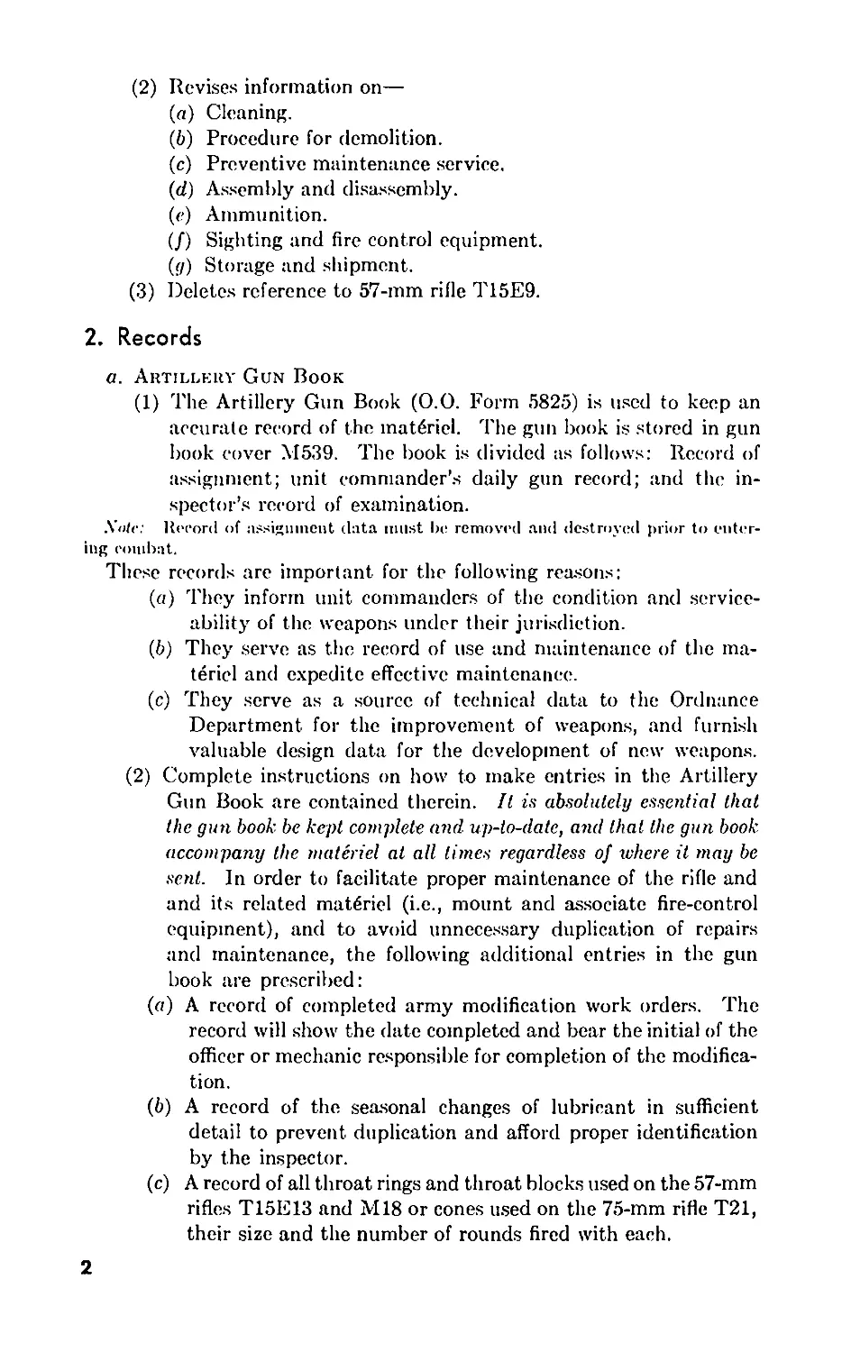
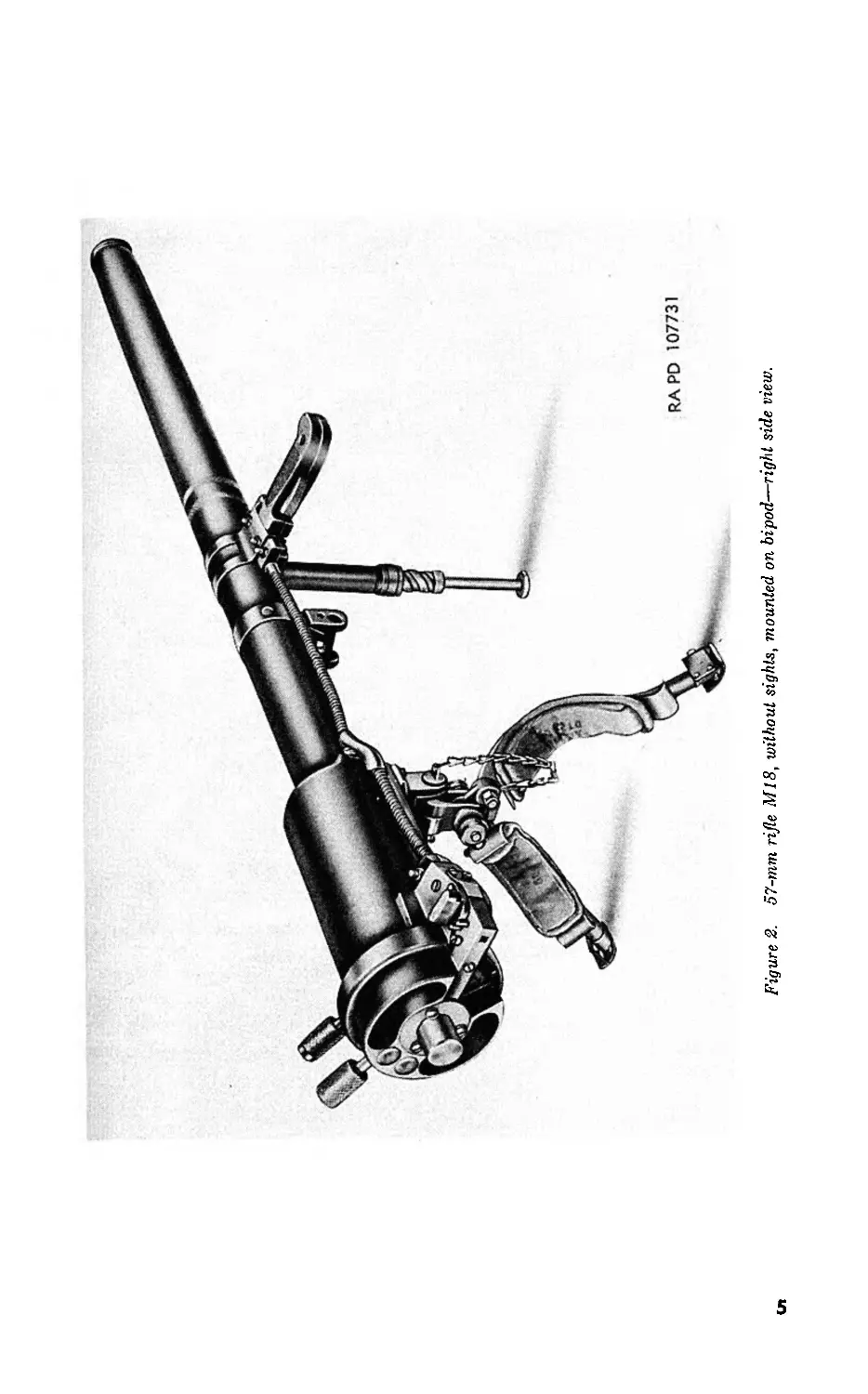
Figure 2. 57-mm rifle M18, without sights, mounted on bipod—right side view.
accordance with instruction No. 7 on the form. Such suggestions are
encouraged in order that other organizations may benefit.
Section II. DESCRIPTION AND DATA
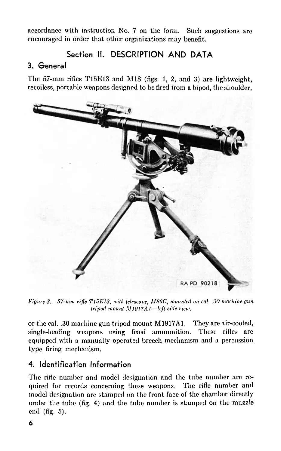
3. General
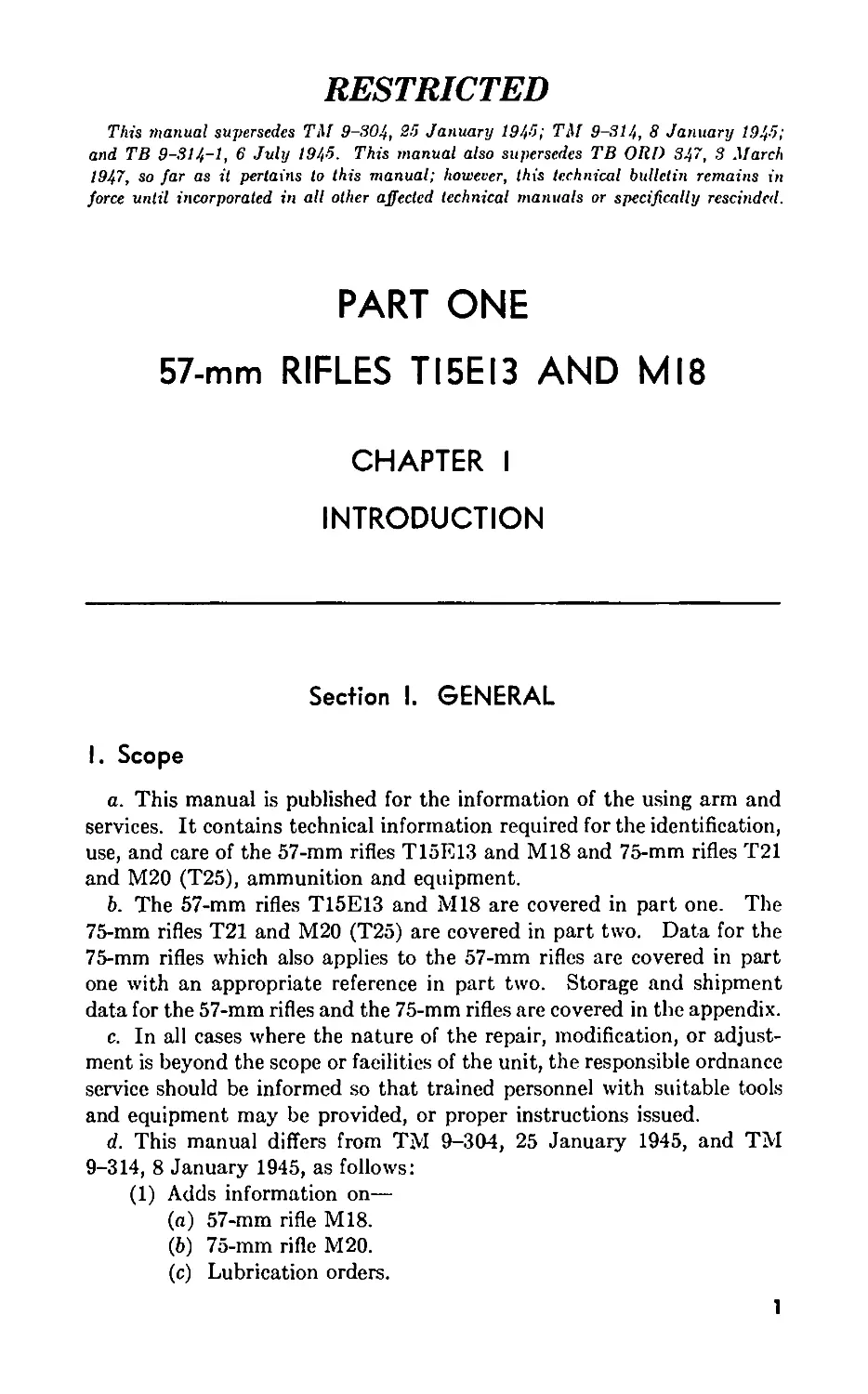
The 57-mm rifles T15E13 and M18 (figs. 1, 2, and 3) are lightweight,
recoiless, portable weapons designed to be fired from a bipod, the shoulder,
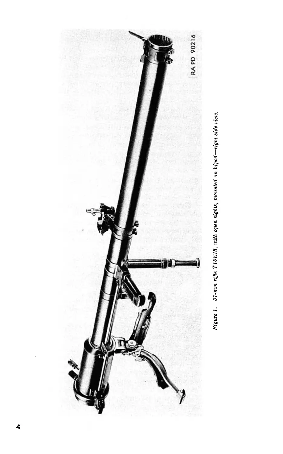
Figure 3. 57-mm rifle T15E13, with telescope, M86C, mounted on cal. .30 machine gun
tripod mount М1917Л1—left side view.
or the cal. .30 machine gun tripod mount M1917A1. They are air-cooled,
single-loading weapons using fixed ammunition. These rifles are
equipped with a manually operated breech mechanism and a percussion
type firing mechanism.
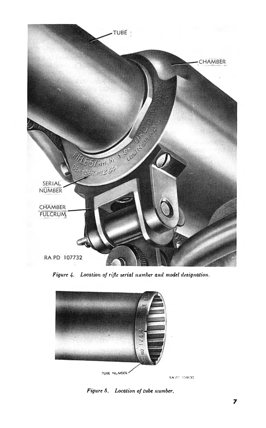
4. Identification Information
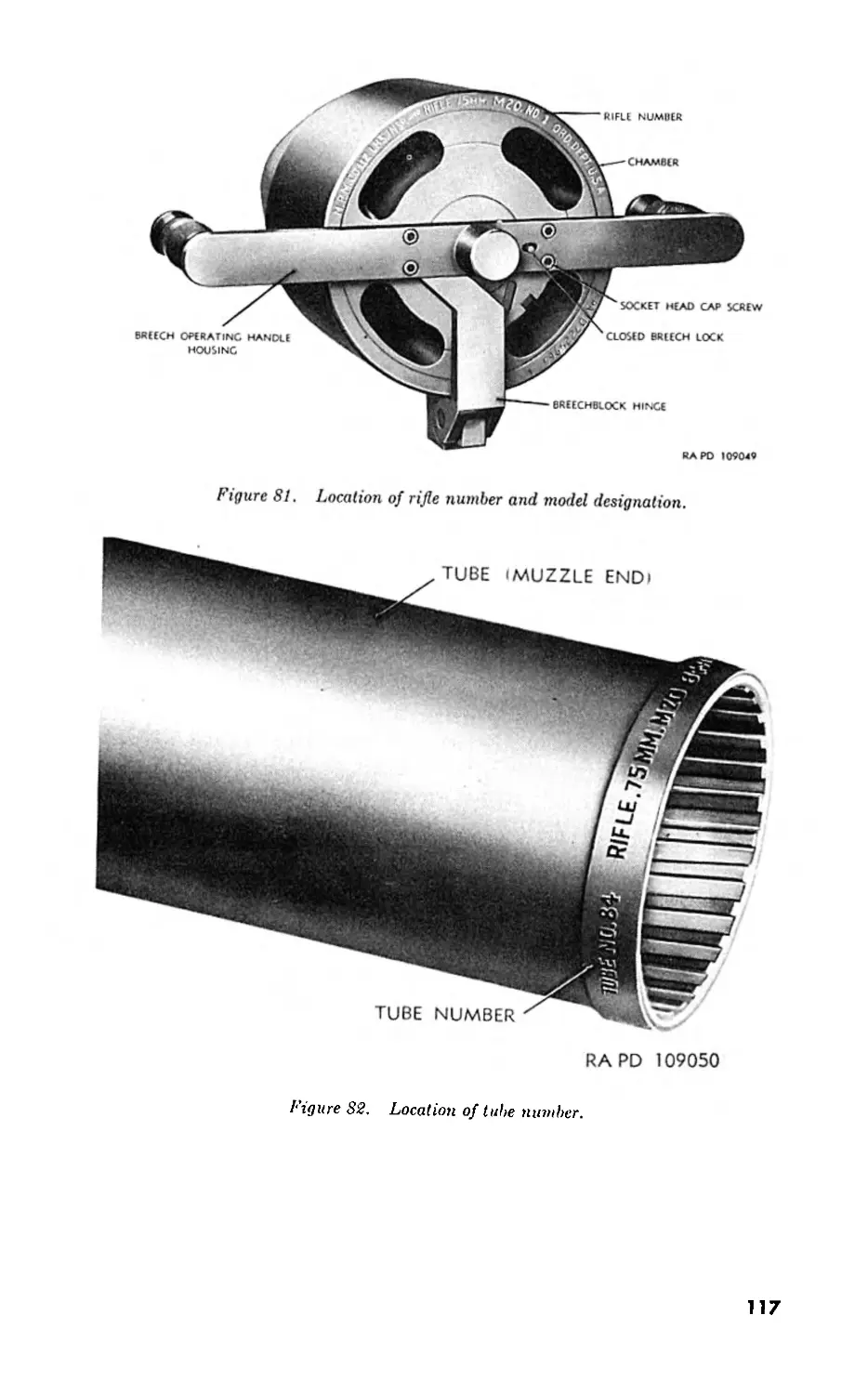
The rifle number and model designation and the tube number are re-
quired for records concerning these weapons. The rifle number and
model designation are stamped on the front face of the chamber directly
under the tube (fig. 4) and the tube number is stamped on the muzzle
end (fig. 5).
6
Figure 4- Location of rifle serial number and model designation.
Figure 5. Location of lube number.
7
5. Differences in Models
a. The primary difference between the 57-mm rifles M18 and T15E13
is the connection between the trigger and the sear. On the rifle M18
(fig. 2) this connection is made by using a wire cable enclosed in a con-
duit, whereas on the rifle (T15E13 (fig. 1) rods enclosed in metal housings
are used.
b. Although other differences between the rifles M18 and T15E13 do
exist they are of such a nature that they do not affect troop use or care,
except as noted in paragraph 66/.
6. Tabulated Data
a. Data Pertaining to 57-mm Rifles T15E13 and M18.
(1) General.
Weight of rifle (for shoulder firing)_________44.4 lb.
Weightof rifle (complete for mounting on tripod). . 40.25 lb.
Weight of rifle (complete with over-all cover M123). 55.00 lb.
Length of rifle_______________________________61.6 in.
Length of tube________________________________48 in.
Length of rifling.............................46.5 in. (20.7 cal.)
Twist of rifling, right-hand................... 1 turn in 30 cal.
Number of lands and grooves...................24
Type of breechblock___________________________ Interrupted lug.
Type of firing mechanism______________________Percussion.
Ammunition____________________________________ For complete ammuni-
tion data, see para-
graphs 86-94.
(2) Performance.
Muzzle velocity_________________________________ 1,200 fps.
Maximum range (approx.)_________________________ 4,340 yd.
Estimated usable life:
Tube and chamber____________________________ 5,000 rds.
Breechblock throat ring and throat blocks_ 500 rds.
b. Data Pertaining to Cal. .30 Machine Gun Tripod Mount
M1917A1.
Weight_________________________________________________ 53.2 1b.
Dimensions (when folded for transportation):
Length_____________________________________________ 36 in.
Width______________________________________________ 10 in.
Height_____________________________________________ 19.5 in.
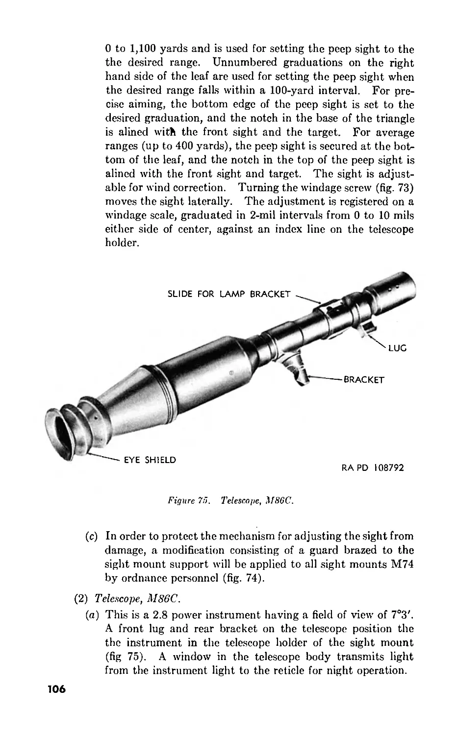
c. Sighting Equipment.
On-carriage Off-carriage
TELESCOPE, M86C TABLE, firing, 57-E-l (abridged)
CASE, carrying, M76
MOUNT, sight, M74
SIGHT, front, M26
LIGHT, instrument, M45
8
CHAPTER 2
OPERATING INSTRUCTIONS
Section I. GENERAL
7. Scope
Chapter 2 contains information for the guidance of the personnel re-
sponsible for the operation of this equipment. It contains information on
the operation of this equipment with the description and location of the
controls and instruments.
Section II. SERVICE UPON RECEIPT OF MATERIEL
8. General
a. Upon receipt of new or used mat6riel, it is the responsibility of the
officer in charge to ascertain whether it is complete and in operating
condition. A record should be made of any missing parts and of any
malfunctions, and any such conditions should be corrected as quickly as
possible.
b. Attention should be given to small and minor parts as these are the
most likely to become lost or out of adjustment and may seriously affect
the proper functioning of the mat6riel.
c. The mat6riel should be cleaned and prepared for service in ac-
cordance with instructions given in paragraph 9 or 10.
9. New Materiel
a. Rifles received from storage will usually be coated with a corrosion
preventive and will be serviced as follows:
(1) Disassemble to the extent prescribed in paragraph 11.
(2) Clean by removing corrosion preventive as outlined in para-
graph 14.
(3) Apply a light film of oil to all parts and assemble. See paragraph
42 for lubrication instructions.
b. Check general condition and appearance of mat6riel.
c. Check spare parts, tools, and equipment with Department of the
Army Supply Catalog ORD 7 SNL C-73.
9
10. Used Materiel
a. Service used mat6riel in the same manner as new mat6riel as de-
scribed in paragraph 9. In addition, cheek the mat6riel for worn,
cracked, rusted, loose, or missing parts and correct any deficiencies.
b. Examine the Artillery Gun Book (par. 2a) to make sure that this
record is up-to-date and that all entries have been made properly. De-
termine whether all army modification work orders have been applied.
A list of current modification work orders is published in FM 21-6.
I I. Disassembly of Rifle Prior to Cleaning
a. Remove the breech mechanism as outlined in paragraph 56 or 63.
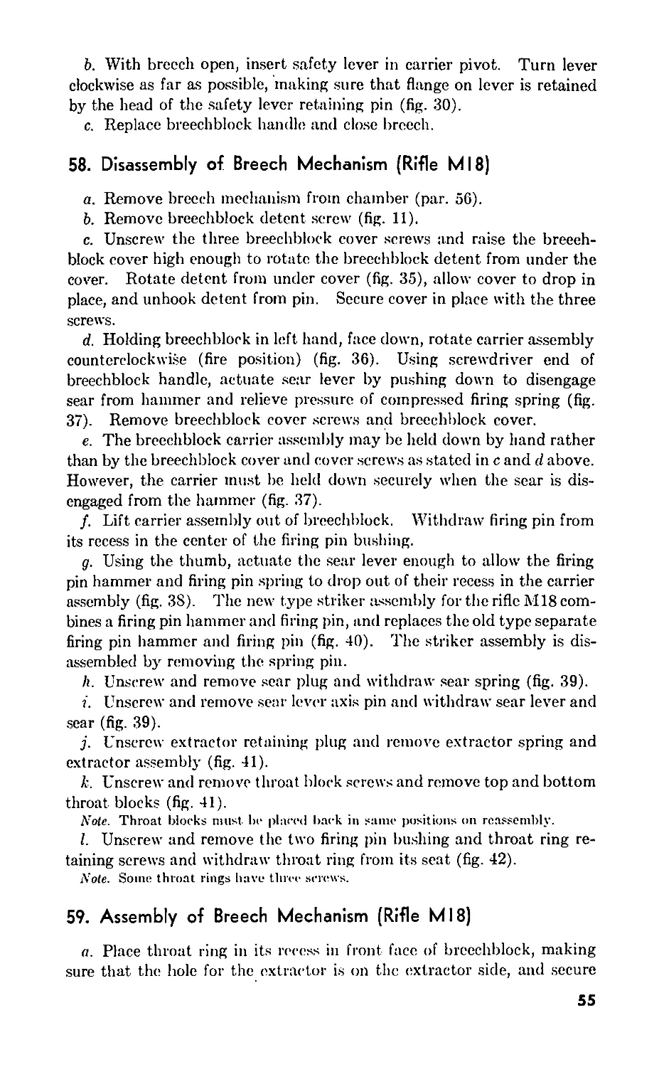
b. Disassemble the breech mechanism as outlined in paragraph 58 or 65.
c. Disassemble the trigger group as outlined in paragraph 70 or 76.
d. Remove the bipod assembly as outlined in paragraph 23j. If the
shoulder pads are assembled to the bipod arms, remove by disengaging
the snap fasteners.
12. Cleaning and Preserving Materials
The following cleaners and preservatives are required for use with this
mat6riel. See TM 9-850 for information additional to that contained
in this manual on the use of these materials. Refer to Department of the
Army Supply Catalog ORD 3 SNL K-l for latest specifications.
CLEANER, rifle bore
CLOTH, bore cleaning
CLOTH, crocus
CLOTH, wiping, cotton
COMPOUND, grease cleaning
ENAMEL, synthetic, lustreless, O.D.
SOAP, issue
SOLVENT, dry cleaning
13. Cleaning, General Instructions
a. Rifles received from storage should be cleaned with dry cleaning
solvent (par. 14).
b. Rifles in use should be cleaned with rifle bore cleaner (par. 15).
c. Components of each rifle should be cleaned separately, for while like
parts are usually interchangeable, the parts originally assembled to the
rifle work best together.
d. The use of gasoline or benzine is prohibited as each presents a fire
hazard.
e. Cleaned parts must be lubricated (par. 42) immediately to prevent
corrosion.
14. Cleaning with Dry-Cleaning Solvent
a. Refer to general instructions for cleaning covered in paragraph 13.
b. When a rifle is removed from storage (par. 2g, Арр. I), dry cleaning
solvent is the preferred cleaner for removing corrosion preventive com-
10
pound. A mixture of one part grea.se cleaning compound to four parts
dry cleaning solvent or kerosene should be used to completely remove
the compound. This mixture can be applied with a brush, swab, or
by dipping.
c. The method of cleaning the bore and chamber when using dry
cleaning solvent is the same as when using rifle bore cleaner as outlined
in paragraph 156.
d. Dry cleaning solvent must not be used to clean the bore or chamber
after firing because it will not readily dissolve the corrosive salts from the
powder composition. Rifle bore cleaner will be used (par. 15).
e. After cleaning with solvent, dry all parts thoroughly with a clean,
lintless wiping cloth or compressed air. Dry bore and chamber using
clean, dry jute burlap.
Caution: Unless special filters or moisture traps are used, compressed
air will contain moisture and must not be used.
f. Immediately lubricate all parts, including the bore and chamber, by
applying a light film of the oil prescribed in paragraph 42 with a clean,
lintless cloth which has been dipped in the oil and then wrung out.
15. Cleaning with Rifle Bore Cleaner
a. Refer to general instructions for cleaning covered in paragraph 13.
b. After firing, the bore and chamber will be cleaned with rifle bore
cleaner when the barrel has cooled to the point where it can be touched
with the bare hand. The cleaner is not a lubricant. Parts requiring
lubrication must be dried after cleaning, and the prescribed lubricant
(par. 42) applied.
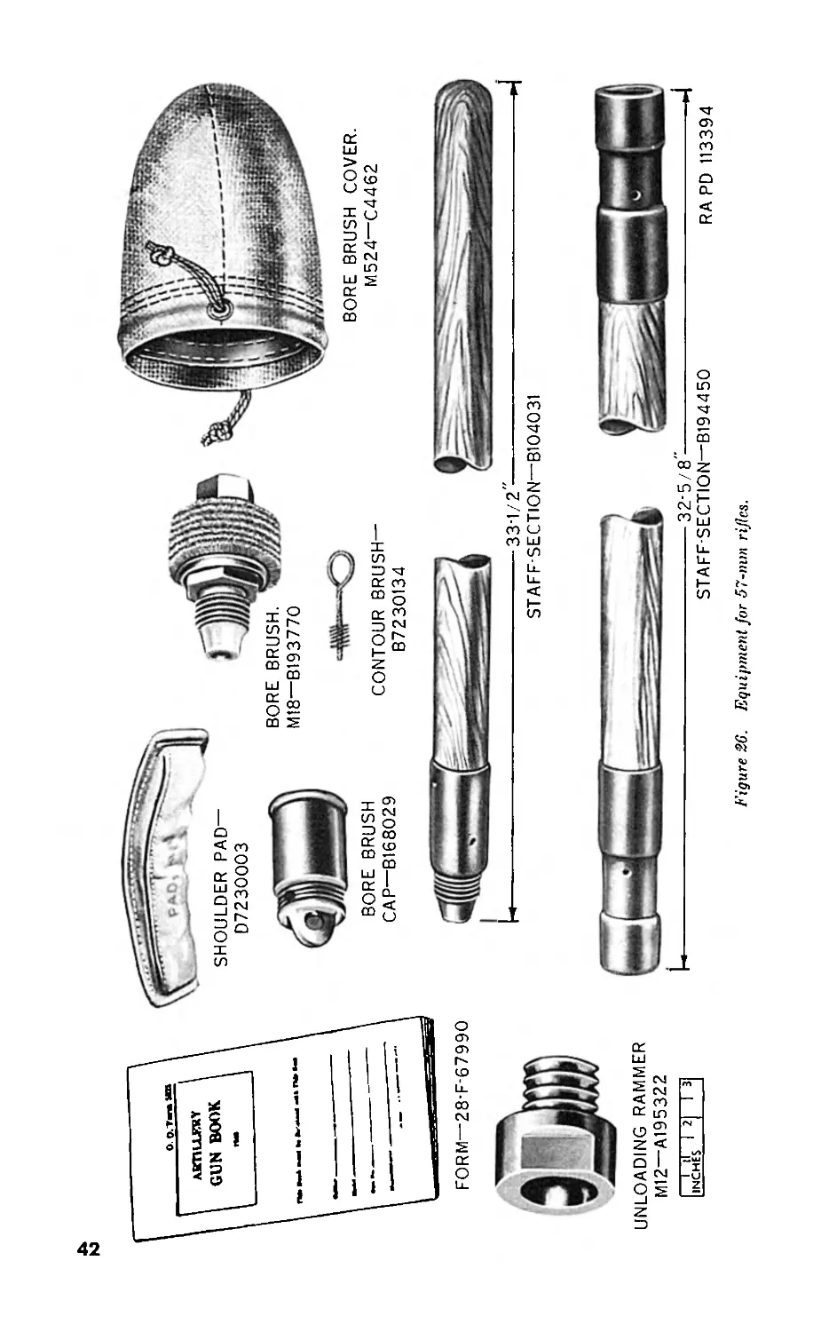
(1) Assemble the bore brush and staff-sections (fig. 26). Saturate
the bore brush with rifle bore cleaner and work the bore brush
through the bore, using a pushing and pulling action.
(2) The design of the chamber is such that it cannot be cleaned by
using the bore brush. Clean the chamber with a cloth swab
saturated with rifle bore cleaner. The swab may be held in
the hand or attached to the end of a stick.
c. If it is anticipated that the weapon will be used or recleaned within
approximately 24 to 48 hours, lubrication for rust prevention will not be
necessary. If the weapon is not to be used or recleaned within 24 to
48 hours, thoroughly dry and then lubricate as outlined in paragraph 42.
16. Assembly of Rifle after Cleaning
a. Assemble the breech mechanism as outlined in paragraph 59 or 66.
b. Install breech mechanism as outlined in paragraph 57 or 64.
c. Assemble the trigger group as outlined in paragraph 71 or 77.
11
d. Place the shoulder pads on the bipod arms and retain in place by-
engaging the snap fasteners. Attach the bipod assembly to the chamber
fulcrum as outlined in paragraph 24a.
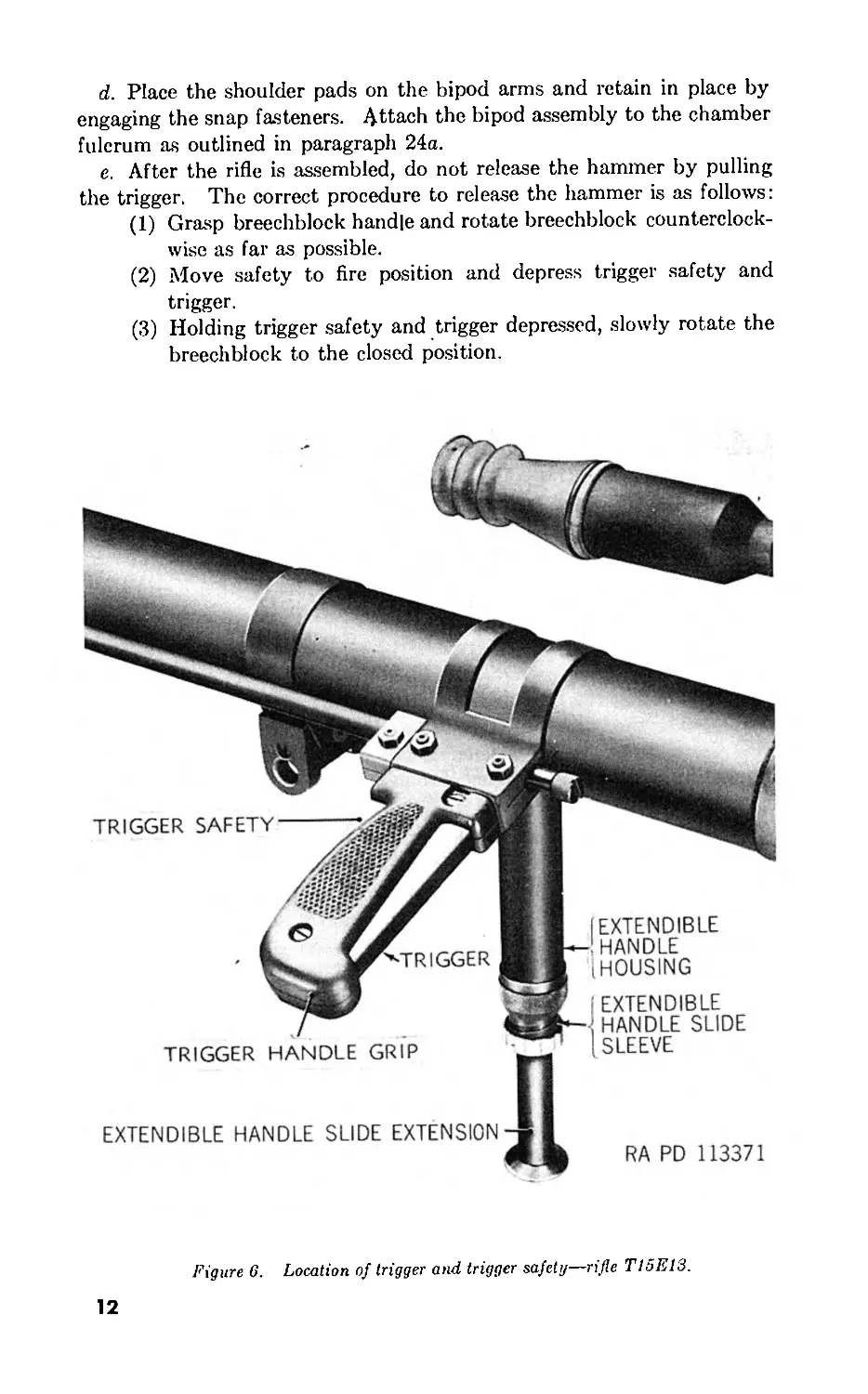
e. After the rifle is assembled, do not release the hammer by pulling
the trigger. The correct procedure to release the hammer is as follows:
(1) Grasp breechblock handle and rotate breechblock counterclock-
wise as far as possible.
(2) Move safety to fire position and depress trigger safety and
trigger.
(3) Holding trigger safety and trigger depressed, slowly rotate the
breechblock to the closed position.
TRIGGER HANDLE GRIP
EXTENDIBLE
HANDLE
(HOUSING
: EXTENDIBLE
; HANDLE SLIDE
SLEEVE
EXTENDIBLE HANDLE SLIDE EXTENSION
RA RD 113371
TRIGGER SAFETY
Figure 6. Location of trigger and trigger safety—rifle T15E13.
12
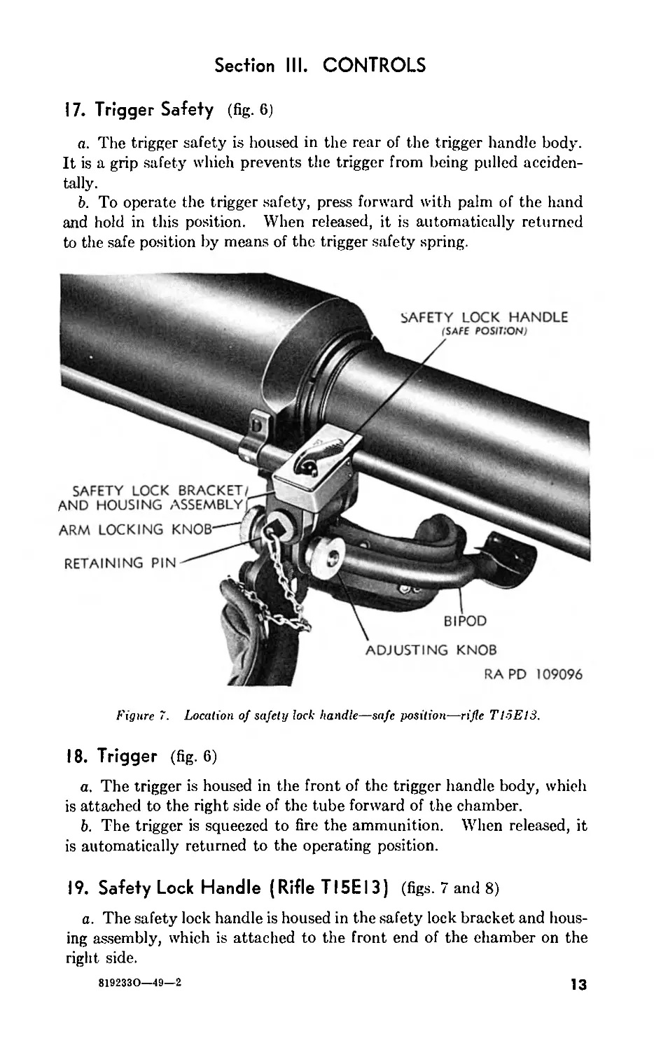
Section III. CONTROLS
17. Trigger Safety (fig. 6)
a. The trigger safety is housed in the rear of the trigger handle body.
It is a grip safety which prevents the trigger from being pulled acciden-
tally.
b. To operate the trigger safety, press forward with palm of the hand
and hold in this position. When released, it is automatically returned
to the safe position by means of the trigger safety spring.
Figure 7. Location of safety lock handle—safe position—rifle T1-5E13.
18. Trigger (fig. 6)
a. The trigger is housed in the front of the trigger handle body, which
is attached to the right side of the tube forward of the chamber.
b. The trigger is squeezed to fire the ammunition. When released, it
is automatically returned to the operating position.
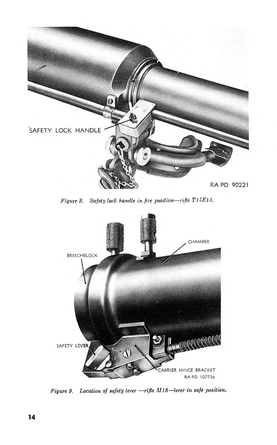
19. Safety Lock Handle (Rifle T15E13) (figs. 7 and 8)
a. The safety lock handle is housed in the safety lock bracket and hous-
ing assembly, which is attached to the front end of the chamber on the
right side.
8192330—49—2
13
Figure S. Safety lock handle in fire position—rifle TI5E13.
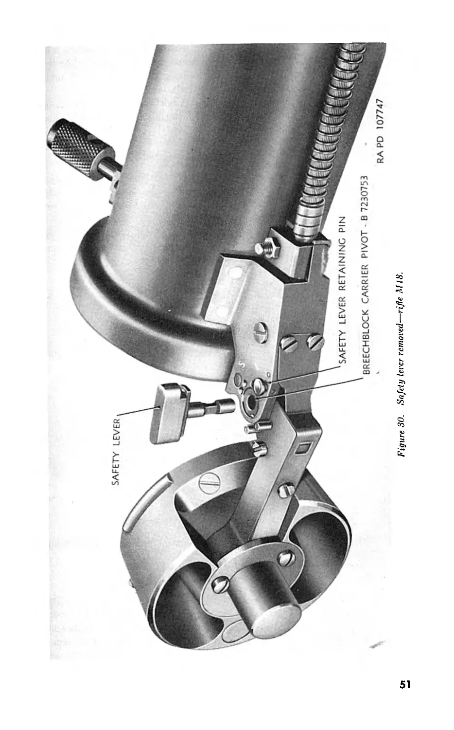
Figure 9. Location of safety lever —rifle M18—lever in safe position.
14
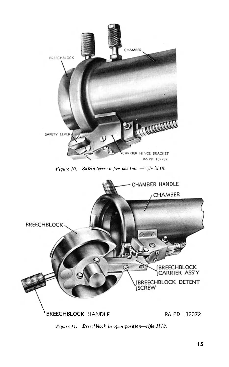
Figure 10. Safety lever in fire position —rifle M IS.
Figure 11. Breechblock in open position—rifle .Ml 8.
15
ELEVATING SCREW
ELEVATING SCREW JOINT PIN ASSEMBLY
b. It has two positions, safe and fire, as indicated by the letters “S”
and “F” stamped on the bracket and housing assembly.
c. In order to connect the trigger and firing rod assemblies so that the
rifle will be fired when the trigger is squeezed, the handle must be man-
ually moved to point to “F.” When the trigger is squeezed, the handle
automatically returns to the safe position.
20. Safety Lever (Rifle M18) (figs. 9 and 10)
a. The safety lever is housed in the carrier hinge bracket, which is
attached to the rear end of the chamber. It has two positions, safe and
fire, as indicated by the letters “S” and “F” stamped on the carrier
hinge bracket.
16
b. In order to connect the safety spring and sear lever so that the rifle
will be fired when the trigger is squeezed, the lever must be manually
moved to point to “F.” When the breech is opened, the lever auto-
matically returns to the safe position.
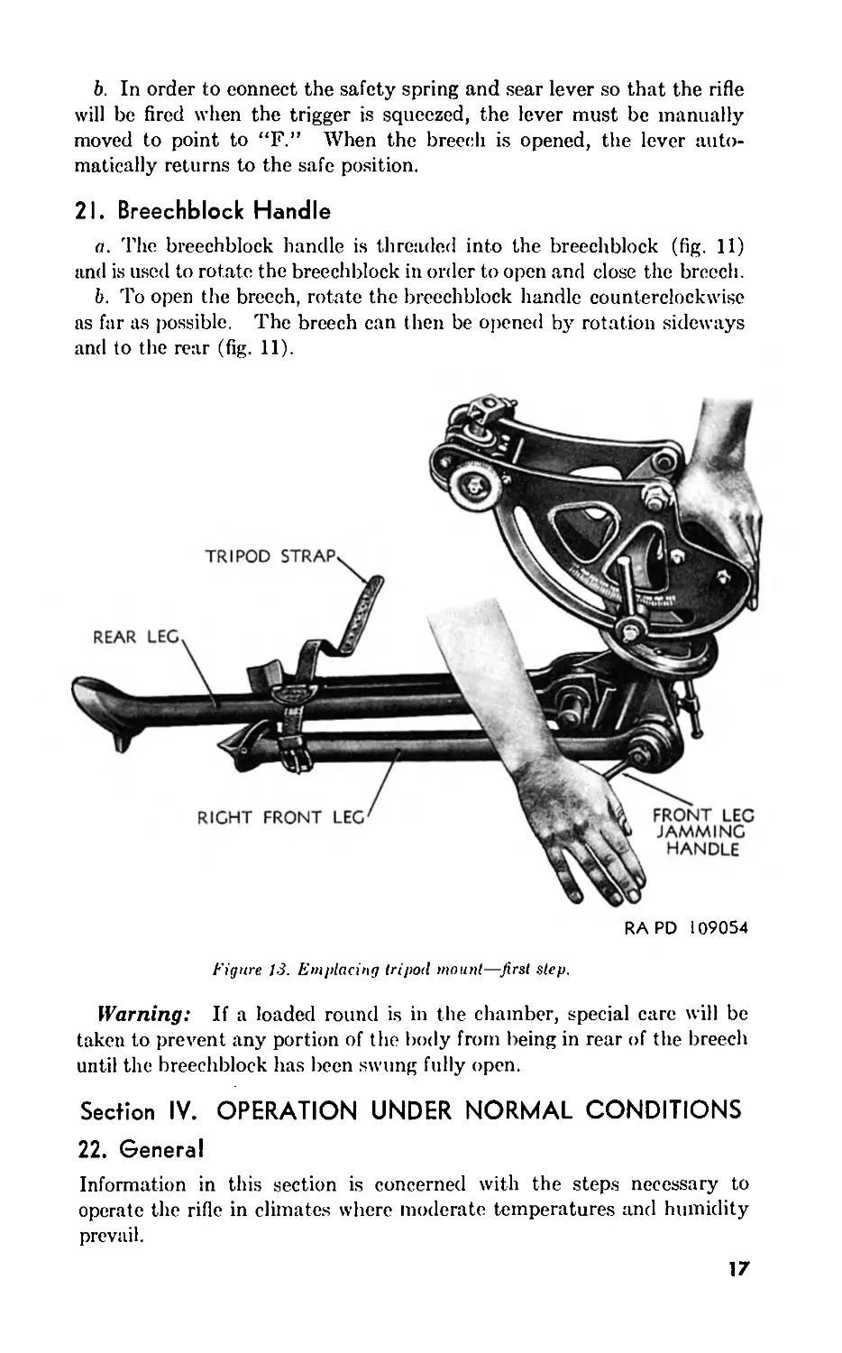
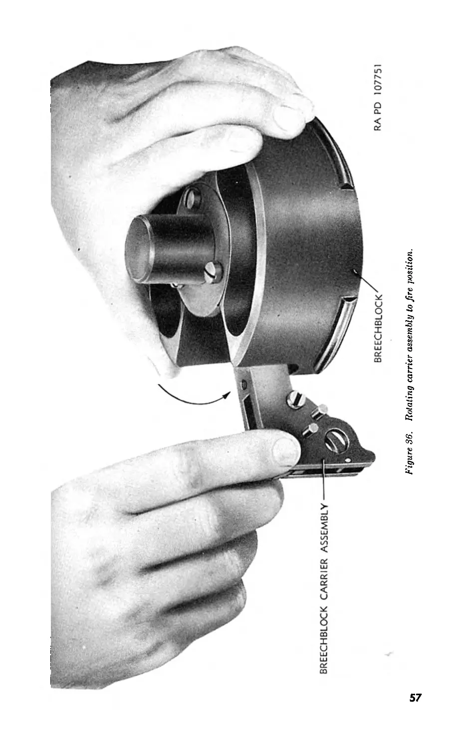
21. Breechblock Handle
a. The breechblock handle is threaded into the breechblock (fig. 11)
and is used to rotate the breechblock in order to open and close the breech.
b. To open the breech, rotate the breechblock handle counterclockwise
as far as possible. The breech can then be opened by rotation sideways
and to the rear (fig. 11).
RAPD 109054
Figure 13. Emplacing tripod mount—first step.
Warning: If a loaded round is in the chamber, special care will be
taken to prevent any portion of the body from being in rear of the breech
until the breechblock has been swung fully open.
Section IV. OPERATION UNDER NORMAL CONDITIONS
22. General
Information in this section is concerned with the steps necessary to
operate the rifle in climates where moderate temperatures and humidity
prevail.
17
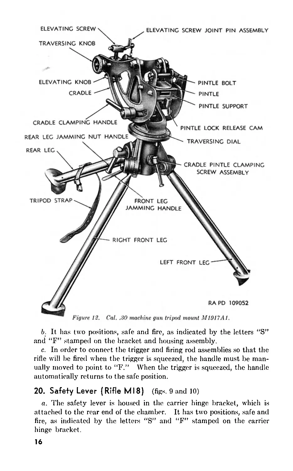
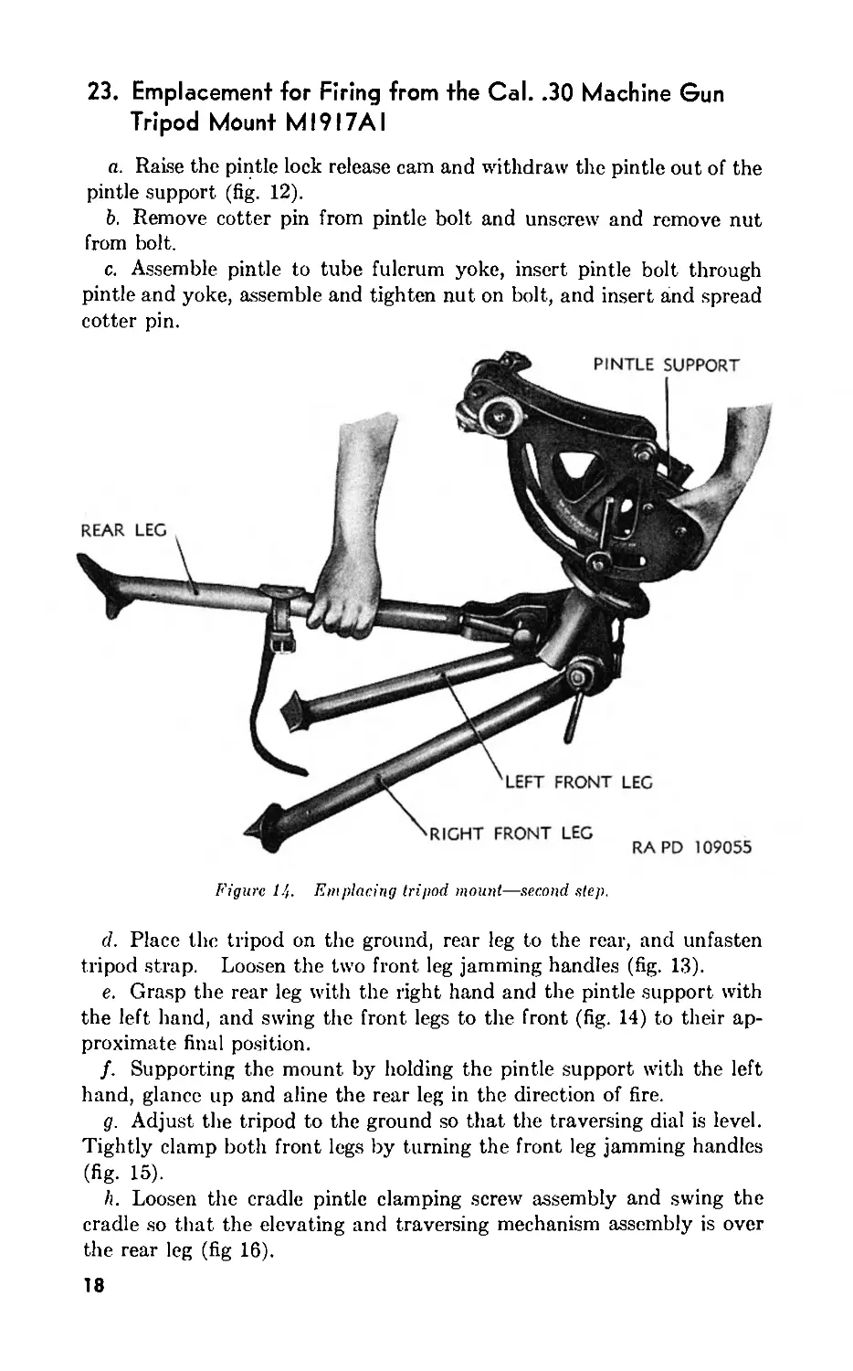
23. Emplacement for Firing from the Cal. .30 Machine Gun
Tripod Mount MI9I7AI
a. Raise the pintle lock release cam and withdraw the pintle out of the
pintle support (fig. 12).
b. Remove cotter pin from pintle bolt and unscrew and remove nut
from bolt.
c. Assemble pintle to tube fulcrum yoke, insert pintle bolt through
pintle and yoke, assemble and tighten nut on bolt, and insert and spread
cotter pin.
Figure 14. Emplacing tripod mount—second step.
d. Place the tripod on the ground, rear leg to the rear, and unfasten
tripod strap. Loosen the two front leg jamming handles (fig. 13).
e. Grasp the rear leg with the right hand and the pintle support with
the left hand, and swing the front legs to the front (fig. 14) to their ap-
proximate final position.
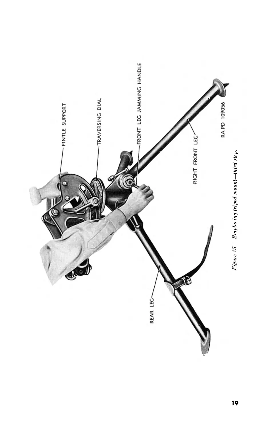
f. Supporting the mount by holding the pintle support with the left
hand, glance up and aline the rear leg in the direction of fire.
g. Adjust the tripod to the ground so that the traversing dial is level.
Tightly clamp both front legs by turning the front leg jamming handles
(fig- 15).
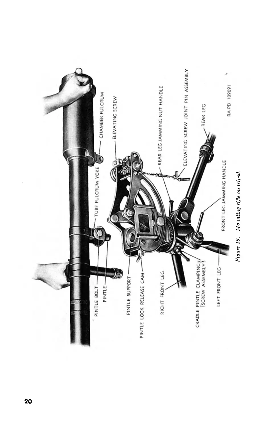
h. Loosen the cradle pintle clamping screw assembly and swing the
cradle so that the elevating and traversing mechanism assembly is over
the rear leg (fig 16).
18
Figure !>. Emplacing tripod mount—third step.
Figure 16. Mounting rifle on tripod.
i. Raise the pintle lock release cam. Remove the elevating screw
joint pin assembly from the elevating screw (fig. 16).
j. Withdraw yoke body pivot of bipod and remove bipod from rifle
(fig. 17).
k. Place the rifle on the mount with the pintle in the pintle support.
Lock pintle in place by releasing pintle lock release cam (fig. 16).
I. Place the chamber fulcrum over the elevating screw and secure in
place by inserting pin (fig. 16).
m. Set desired azimuth by loosening the cradle pintle clamping screw
assembly and moving the cradle for major changes or by turning the
traversing knob for minor changes (fig. 12).
n. Set desired elevation by loosening the cradle clamping handle and
moving the cradle up or down for major changes or by turning the eleva-
tion knob for minor changes.
24. Emplacement for Firing from Bipod
a. Place yoke of the bipod into the chamber fulcrum on the rifle and
secure with yoke body pivot attached to the bipod by a chain (fig. 18).
(1) The bipod for the rifle T15E13 and for the old type manufacture
of the rifle M18 is shown in figure 18.
(2) The new bipod for the new type manufacture of the rifle M18
is shown in figure 17. The yoke body pivot is attached to the
left bipod arm. The yoke lock pin extends to the right (fig 17).
The new type manufacture of the rifle M18 has a different
chamber fulcrum that eliminates the need for a yoke saddle
(fig- 18).
RA PD 113398
Figure 17. Bipod assembly—1)7231363—for rifle MIS.
21
Figure IS. Disassembling or assembling bipod to rifle.
b. Adjustment for elevation may be made by adjusting the bipod arms
or the extendible handle assembly.
c. To spread the bipod arms, loosen the adjusting knob (fig. 19), move
the arms to the desired position, and tighten the knob.
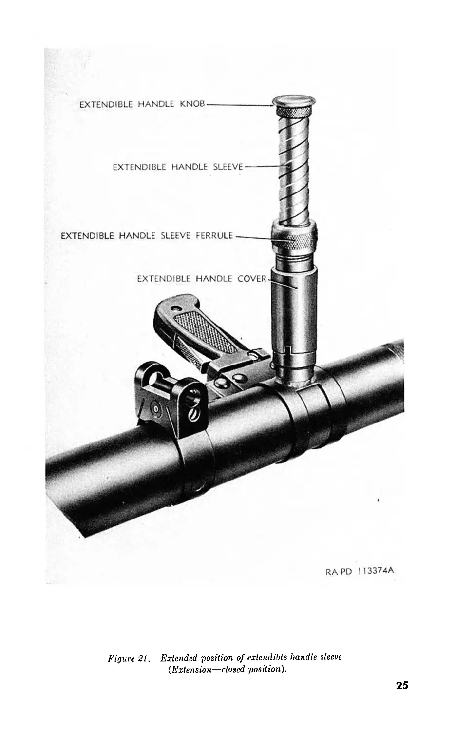
d. The height of the extendible handle assembly can be adjusted by the
extendible handle extension and/or the extendible handle sleeve. The
extension has two positions—extended (fig. 20) and closed (fig. 21). On
the standard type handle, the extension is locked in the extended position
by pulling the extension out against the tension of the spring inside the
extension and rotating the extension one-quarter turn counterclockwise
so that the two guides on the extension fit into the notches in the extendi-
ble handle sleeve bushing. The sleeve is threaded and can be screwed
in or out of the handle to any desired position (fig. 21). It is locked in
position by tightening the ferrule.
e. If the T15E13 rifle is equipped with the old type extendible handle
assembly (7229371) (fig. 20), which utilizes a spring-loaded ball catch
to hold the extension in an extended position, it should be replaced with
the standard type handle (7231849) (fig. 20) which employs a sleeve
22
bushing and sleeve grip, and the old type handle be returned, through
supply channels, to Watervliet Arsenal for reworking.
Warning: Firing the rifle, using the old extendible handle (fig 20)
with the telescoping section in the fully extended position, is prohibited.
Firing is permissible if only the threaded portion of the extendible handle
is extended.
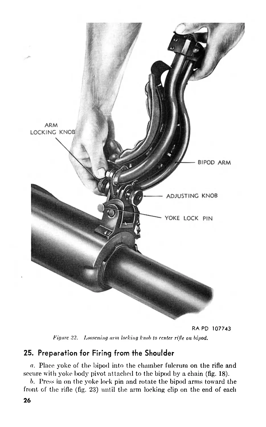
f. The rifle can be leveled on the bipod by loosening the arm locking
knob (fig. 22), moving the rifle to the desired position, and tightening
the knob.
Figure 19. Loosening adjusting knob to adjust spread of bipod arms.
23
Figure 20. Extended, position of extendible handle extension
{Sleeve—closed position).
24
EXTENDIBLE HANDLE
EXTENDIBLE HANDLE KNOB
EXTENDIBLE HANDLE SLEEVE FERRULE
EXTENDIBLE HANDLE COVER
RAPD 113374A
Figure 21. Extended position of extendible handle sleeve
(.Extension—closed position).
25
RA PD 107743
Figure 22. Loosening arm locking l:nol> to center rifle on bipod.
25. Preparation for Firing from the Shoulder
a. Place yoke of the bipod into the chamber fulcrum on the rifle and
secure with yoke body pivot attached to the bipod by a chain (fig. 18).
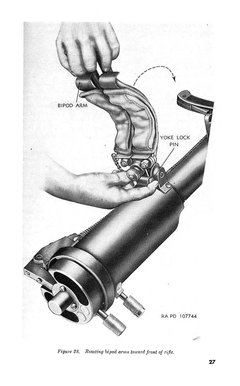
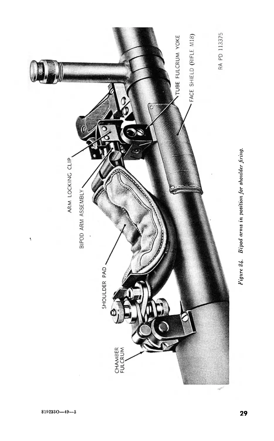
b. Press in on the yoke lock pin and rotate the bipod arms toward the
front of the rifle (fig. 23) until the arm locking clip on the end of each
26
Figure 23. Rotating bipod arms toward front of rifle.
27
bipod arm rests between the lugs of the tube fulcrum yoke (fig. 24). In
t his position the pads on the bipod form a rest for the shoulder.
26. Loading a Cartridge into the Rifle
Note: Normal operation of the rifle requires two men; one to load the ammuni-
tion and remove the empty case and one for firing.
a. Rifle on Shoulder (Standing Position).
(1) When loading, with the gunner firing from the shoulder, the
assistant gunner (loader) stands with his back to the gunner
having the chamber of the rifle over his right shoulder. The
breechblock handle is grasped by the loader’s right hand, palm
toward his face, and rotated counterclockwise until stopped by
contact with the breechblock carrier. The breech can then be
opened by swinging the breechblock sideways and to the rear.
(2) With the breech open, check for and remove any foreign matter
that may be lying in bore or chamber.
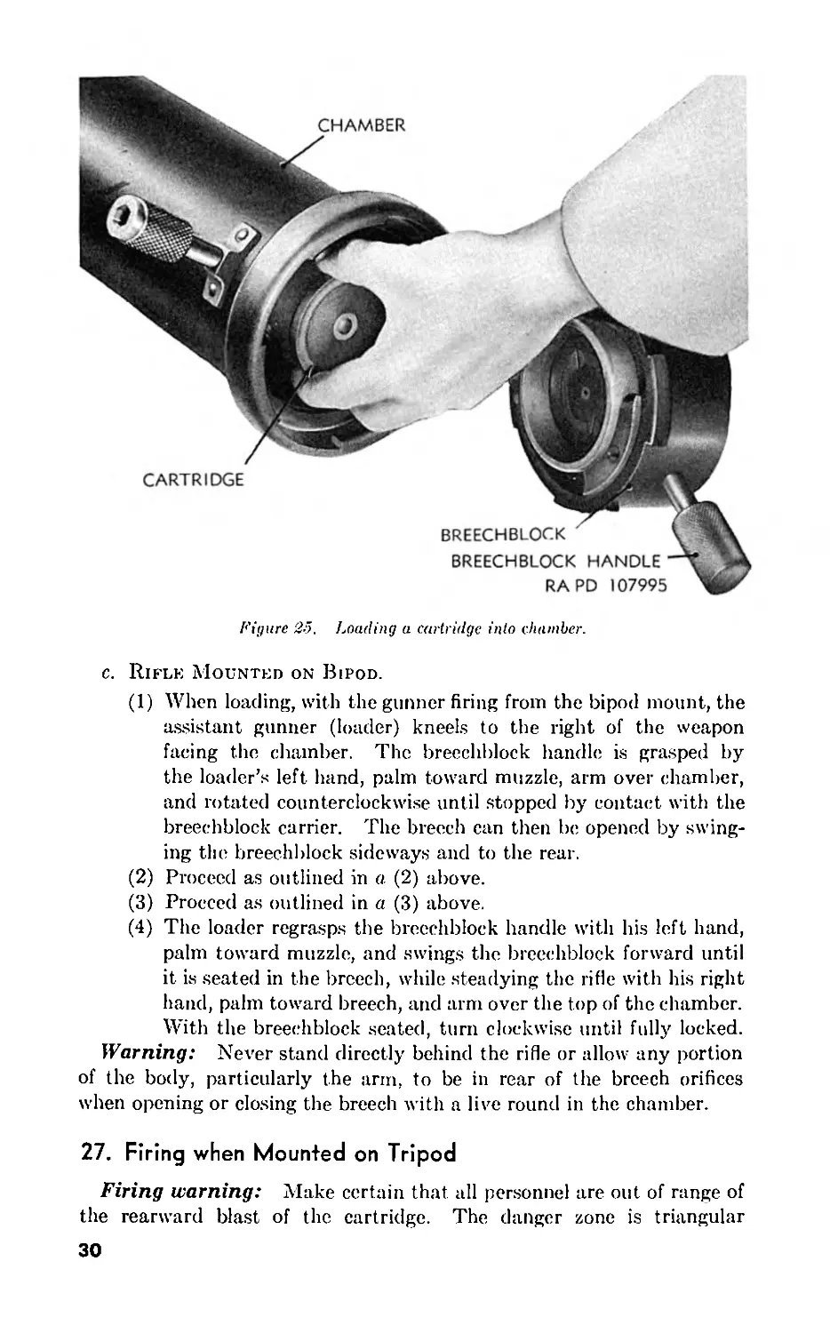
(3) The round is inserted with the loader’s left hand and supported
from the bottom and guided with his right hand. When the
rotating band on the projectile contacts the lands in the tube
(fig. 25), rotate the cartridge case, either in a clockwise or
counterclockwise direction, to aline the engraving on the
rotating band of the projectile with the rifling in the tube.
When alined, push the cartridge into the chamber until stopped
by the headspace bands on the cartridge case.
(4) The loader regrasps the breechblock handle with his right
hand, palin toward his face, and swings the breechblock for-
ward until it is seated in the breech, while steadying the rifle
with his left hand, pahn to the rear, and left arm over the top
of the chamber. With the breechblock seated, turn clockwise
until fully locked.
b. Rifle on Shoulder (Kneeling or Sitting Position) and When
Mounted on Tripod.
(1) When loading, with the gunner firing from the shoulder, in a
kneeling or sitting position, or when mounted on a tripod mount,
the assistant gunner (loader) kneels at the right side of the rifle
facing to the rear. The breechblock handle is grasped by the
loader’s right hand, pahn toward his face, ann under chamber,
and rotated counterclockwise until stopped by contact with the
breechblock carrier. The breech can then be opened by
swinging the breechblock sideways and to the rear.
(2) Proceed as outlined in a (2) above.
(3) Proceed as outlined in a (3) above.
(4) Proceed as outlined in a (4) above.
28
8192330-49-
Figure 24. Bipod arms in position for shoulder firing.
Figure 25. Loading a cartridge into chamber.
c. Rifle Mounted on Bipod.
(1) When loading, with the gunner firing from the bipod mount, the
assistant gunner (loader) kneels to the right of the weapon
facing the chamber. The breechblock handle is grasped by
the loader's left hand, palm toward muzzle, arm over chamber,
and rotated counterclockwise until stopped by contact with the
breechblock carrier. The breech can then be opened by swing-
ing the breechblock sideways and to the rear.
(2) Proceed as outlined in a. (2) above.
(3) Proceed as outlined in a (3) above.
(4) The loader regrasps the breechblock handle with his left hand,
palm toward muzzle, and swings the breechblock forward until
it is seated in the breech, while steadying the rifle with his right
hand, palm toward breech, and arm over the top of the chamber.
With the breechblock seated, turn clockwise until fully locked.
Warning: Never stand directly behind the rifle or allow any portion
of the body, particularly the arm, to be in rear of the breech orifices
when opening or closing the breech with a live round in the chamber.
27. Firing when Mounted on Tripod
Firing warning: Make certain that all personnel are out of range of
the rearward blast of the cartridge. The danger zone is triangular
30
shaped and extends approximately 50 feet to the rear of the point of
emplacement and covers a space 20 feet on either side of the axis of the
emplaced rifle. No personnel should face the weapon within 100 feet
of the rear of its breech because of danger due to flying particles thrown
up by the blast action.
a. The gunner kneels on the left side of the rifle, places his left arm
under the tube, and grips the trigger handle with his left hand so that the
fingers encircle the trigger and the thumb contacts the trigger safety.
b. The assistant gunner (loader) takes his position and proceeds to
load the weapon as outlined in paragraph 265. When the loader has
closed and locked the breech, he positions the safety on “fire” and signals
the gunner that the weapon is ready to fire.
c. To fire, the gunner presses the trigger safety with the thumb while
squeezing the trigger. Grip the elevating handwheel of the tripod with
the right hand.
d. Personnel firing the rifle should place ear plugs or cotton in their
ears.
Caution: After the weapon has been fired continuously, the chamber
will be hot and care must be exercised to avoid injury when operating
the breech.
28. Firing when Mounted on Bipod
a. The gunner lies in a prone position at the left side of the rifle, places
his right arm under the tube and grasps the trigger and safety trigger.
He grasps the extendible handle assembly with his left hand.
b. The assistant gunner (loader) takes his position and proceeds to
load the weapon as prescribed in paragraph 26c. When the loader has
closed and locked the breech, he positions the safety on “fire” and
signals the gunner that the weapon is ready to fire.
c. To fire, the gunner presses the trigger safety with the thumb while
squeezing the trigger with the fingers.
Warning: When firing in the prone position, the body should be at
an angle of at least 45° to the direction of fire so as to avoid injury from
the back blast of the ammunition.
29. Firing from the Shoulder
a. With the pads on the bipod to protect his shoulder, the weapon is
placed on the gunner’s right shoulder and held steady by grasping the
extendible handle assembly with his left hand and the trigger handle with
his right hand. A new fulcrum assembly for the M18 rifle includes a
face shield which protects the gunner from the heat of the tube (fig. 24).
b. The assistant gunner (loader) takes his position, dependent upon
the position of the gunner, and proceeds to load the weapon as prescribed
31
in paragraph 26a or b. When the loader has closed and locked the breech,
he positions the safety on “fire” and signals the gunner that the weapon
is ready to fire.
c. To fire, the gunner presses the trigger safety with the thumb while
squeezing the trigger with the fingers.
30. Unloading an Empty Case or Complete Round from the Rifle
a. Open the breech as outlined in paragraph 26a, b, or c, as applicable.
In all instances the empty case is caught with the tips of the fingers and
thumb of the right or left hand and the empty case is discarded to the
rear. The right hand is used to extract the case when firing from the
shoulder; the left hand when firing from either the bipod or tripod mount.
The empty case is always hot immediately after firing and must be ex-
tracted quickly to prevent injury.
b. If the empty cartridge case is not extracted sufficiently upon opening
the breech to permit removal of the case by hand, proceed as follows:
Assemble the staff-sections and unloading rammer M12 (fig. 26), insert
the rammer into the bore from the muzzle end, and force the case to the
rear. Refer to paragraph 51 for probable causes and remedial action
necessary to prevent recurrences.
c. If it is desired to remove the complete round from the rifle and the
extractor fails or the case becomes separated from the projectile, the
following method, under the direct supervision of an officer, will be used:
(1) Assemble staff-sections and unloading rammer M12 (fig. 26).
Make sure that the rammer is free of foreign matter.
(2) Place the rifle at approximately 5° elevation and open the breech.
(3) Insert the rammer into the bore from the muzzle end until it
contacts the projectile. Push, or, if necessary, tap the staff
lightly, until the round is dislodged from the riffling. Remove
the round from the breech.
(4) If cartridge ease has been extracted but the projectile has re-
mained in the bore, proceed as follows:
Caution: If the case becomes separated from the projectile, powder
will be spilled in the chamber. Thoroughly clean chamber of any
powder before proceeding with the following instructions.
(a) Place rags or wiping cloths in the bottom of the chamber to
protect the projectile as it drops into the chamber and close
the breech.
(5) Dislodge the projectile as outlined in steps (1), (2), and (3)
above.
(c) Open the breech and remove the rags and the projectile.
Remove the cartridge case and projectile from the vicinity of
firing and make a report to the local ordnance officer.
32
31. Misfire
a. The 57-mm rifles T15E13 and M18 exhibit three general types of
failure to fire when the trigger is pulled. These types of failures, together
with their causes, are listed in this subparagraph. Corrections of these
malfunctions are listed in b below.
(1) Firing pin or ammunition failure. On pulling the trigger, the
hammer is heard to drive the firing pin forward but the round
fails to fire.
(n) If the primer indentation is normal, the ammunition is at fault.
(6) If the primer indentation is not normal, the failure to fire
may have been caused by insufficient firing pin protrusion,
insufficient striking foree on the primer caused by a worn,
dirty, or broken firing pin, a weak or broken hammer spring,
or binding of the hammer.
(2) Firing linkage failure. On pulling the trigger, the hammer is
not heard to fall. This failure is usually caused by a deficiency
within the firing linkage which does not allow-disengagement of
the sear. The failure to retract the sear may be caused by one
of the following:
(n) Too much slack in the firing linkage.
(b) Failure of the firing rod to engage the trigger rod in the safety
lock bracket (T15E13) due to broken or maladjusted parts.
(c) Failure of the safety spring to engage the sear lever (M18).
(d) Broken, worn or missing sear lever, bellerank (T15E13), firing
rod (T15E13), firing cable (M18), safety spring (M18), or
trigger link.
(3) Hammer in forward position before trigger is pulled. On pulling
the trigger, the firing linkage operates satisfactorily, but the
hammer is already forward. This failure is usually caused by
a maladjustment in the firing linkage whereby the sear is held
in the disengaged position or disengages from the firing hammer
as the breech is being closed, allowing the hammer to move
forward following the cocking earns on the firing pin bushing
as the breechblock is rotated to the locked position. A mal-
adjustment which could effect the retraction of the sear from
engagement with the firing hammer or retain the sear in the
retracted position might consist of one or more of the following:
(«) When the trigger was pulled on the previous round, either the
firing cable or firing rod was held in the forward position due
to binding or dirt in the linkage.
(5) The location of the bellcrank stop or the firing rod stops did
not permit sufficient counterclockwise rotation of the bell-
crank (T15E13) to allow clearance for the sear lever to seat
on breech closing without rotating counterclockwise to retract
the sear.
33
(c) The adjusting screws on the sear lever (T15E13) were at
maximum protrusion and caused the sear lever on contact
with the hellcrank to rotate on breech closing sufficient to
retract the sear.
(d) The sear lever stop (M18) is bent or dirty or the notch for
the sear lever stop is sufficiently full of dirt to hold the sear
lever while in rotation thereby holding the sear in the retracted
position.
(e) The sear recess is full of dirt or carbon, or the sear spring
broken so that the sear spring did not move the sear forward
to engage the firing hammer when the hammer was forced to
the rear upon unlocking the breechblock.
b. When a failure to fire is encountered, corrective action will be taken
as follows:
(1) Firing pin or ammunition failure. On pulling the trigger, if it
is known that the hammer has driven the firing pin forward as
outlined in n(l) above, personnel will move to positions of
safety and wait 1 minute before opening the breech. In case
the weapon is being fired from the shoulder, the assistant gunner
(loader) will assist the gunner in removing the weapon and
placing it on the ground. Only one person will be near the
weapon when the breech is opened and the round removed and
examined.
(a) If the primer indentation appears normal, the round will be
turned over to the local ordnance representative. If ord-
nance assistance is not available, the round will be removed
to a safe distance and kept separated from other ammunition,
and subsequently reported to ordnance personnel for dis-
position. Firing may then continue.
(t>) If the primer indentation is not normal, the local ordnance
representative will be requested to examine the rifle to de-
termine the cause of failure to fire. Examine the breech
mechanism for possible causes of malfunctioning as follows:
With the breechblock swung open, the sear should be retracted
by means of the sear lever, and the breechblock rotated to
the locked position while still open.
1. If the firing pin protrudes from the face of the breechblock
and does not appear broken or eroded, protrusion of the
firing pin may have been reduced by accumulated dirt or
carbon on the firing pin shoulder or in the firing pin bushing.
Disassemble the breechblock and clean the firing pin, firing
pin recess in the firing pin bushing, and hammer. Assemble
the breechblock. Firing may continue, starting with the
round with improper primer indentation.
2. If the firing pin is broken or if the point of the firing pin is
34
eroded, replace the firing pin. Firing may continue, starting
with the round with improper indentation.
(2) Firing linkage failure or hammer in forward position before trigger
is pulled. On pulling the trigger, if the hammer is not heard to
fall as outlined in o(2) and (3) above, the breechblock should
not be opened immediately. Another attempt to fire should be
performed as follows:
(n) If the safety lever has operated satisfactorily on the first
attempt to fire (T15E13), examine the safety lever to see if it
has moved from “fire” to “safe” upon pulling the trigger. If
the safety lever has moved from “fire” to “safe,” the hammer
may or may not be in the forward position. Rotate the safety
lever from “safe” to “fire” and make another attempt to fire.
(6) If the hammer is in the cocked position and did not fall on
the first attempt to fire, the hammer will usually fall and fire
the rifle on the second attempt if the fault is excessive slack
in the firing linkage. If the rifle fires on the second attempt,
firing should be discontinued until ordnance personnel corrects
the deficiency.
(c) If the hammer does not fall on the second attempt to fire, an
attempt should be made to open the breech.
1. If the breechblock is difficult to open, slowly release the
breechblock after it has been rotated 15° to 20° to unlock.
If, when released, the breechblock rotates toward the locked
position, the hammer is forward and the hammer is pressing
against the cocking cams on the firing pin bushing, causing
the breechblock to rotate toward the locked position. Open
the breechblock and remove the round. Request local ord-
nance personnel to examine the rifle and correct the de-
ficiency.
2. If the breechblock opens easily, the hammer has not fallen
but is retained in the rearward position by the sear. Remove
the round. Request local ordnance personnel to examine
the rifle and correct the deficiency.
3. If ordnance assistance is not available, examine the unloaded
rifle to determine whether the safety cam (T15E13) is
functioning. The set screw in the safety cam may have
become loose. If so, the earn does not rotate with the safety
shaft to force the spring safety flexible extension on the firing
rod into engagement with the catch on the trigger rod to form
a connection of the firing linkage between trigger and sear.
If the set screw is loose, tighten the screw and perform the
firing sequences without a round in the chamber. If the
weapon functions satisfactorily, firing may continue, starting
with the round which was removed from the chamber.
35
c. In the event that the rifle has been fired continuously for a consider-
able length of time before misfire, the barrel will be hot. Stand clear of
the rifle until it has cooled and then remove the round. The heat of the
barrel can cause the fuze, projectile filler, or propellant to explode or
“cook off,” particularly if the cylindrical pellets of propellant have cut the
cartridge case liner and have fallen into the chamber. Inspection of am-
munition prior to firing will reveal such ruptures in case liners. Rounds
with ruptured case liners will not be used but will be removed to a safe
distance from the firing point and reported to ordnance personnel for
disposition.
Section V. OPERATION UNDER UNUSUAL CONDITIONS
32. General
The procedures for the mechanical operation of the rifle are the same
for operation under either usual or unusual climatic conditions. In addi-
tion to the normal preventive maintenance service specified throughout
this manual, special care in cleaning and lubrication should be observed
where extremes of temperature, humidity, and atmospheric conditions
are present. Proper cleaning and lubrication not only insure proper
operation and functioning but also guard against excessive wear of the
working parts and deterioration of the mat6riel.
33. Operation in Cold Climates
a. In temperatures below freezing, it is necessary that the working
parts of the rifle be kept absolutely free from moisture. Take special
care to remove excessive oil on the working parts because it will congeal to
such an extent as to cause sluggish operation and functioning, or complete
failure. This applies, in particular, to the small spring-operated parts in
the breech mechanism and trigger group. The tube may be bulged by
firing a round when congealed lubricants are in the bore.
b. Protect rifles from frost when not in use with the proper covers.
c. Allow rifles taken into heated buildings to come to the temperature
of the building before cleaning. Immediately after they reach room
temperature, disassemble to the extent outlined in paragraph 11. Thor-
oughly wipe all moisture from all parts as well as the bore and chamber to
prevent rusting. Then thoroughly clean by the method outlined in para-
graph 15 and lubricate as outlined in paragraph 42.
34. Operation in Hot Climates
a. In hot climates, the thin film of oil necessary for operation and
preservation will be quickly dissipated. Inspect rifles frequently, paying
particular attention to unexposed surfaces such as the bore and chamber,
36
springs and spring seats, firing pin, and like places where corrosion might
occur and not be quickly noticed. When necessary renew a film of the
oil prescribed in paragraph 42. Keep screws and pins lightly oiled to
prevent rust from attacking them and “freezing” them in place.
b. Protect rifles not in use with the proper covers.
c. Perspiration from the hands is a contributing factor to rusting
because it contains acid. After handling, clean, wipe dry, and restore
the oil film.
35. Operation under Excessively Sandy or Dusty Conditions
a. In localities where dust and sand storms are prevalent, carefully
protect the rifles with proper covers. Dust and sand will enter the
mechanism and bore and stick on lubricated surfaces, forming a gummy
paste which may clog the rifle and cause malfunction. This paste will
also act as an abrasive and will cause undue wear of the moving parts
of the rifle.
b. Under such conditions thoroughly clean and lubricate the rifles as
often as necessary (c below).
c. Disassemble to the extent outlined in paragraph 11. Clean by the
method outlined in paragraph 15. Lubricate with the oil specified in
paragraph 42. Apply the oil to moving parts and contacting surfaces
only. The film of oil will be as light as possible for proper functioning of
the rifle.
36. Operation in Excessively Moist or Salty Atmosphere
Salt air is conducive to quick rusting as the salt has a tendency to
destroy the rust-preventive qualities of the oil. When operating the
rifle under these conditions, treat it in a manner similar to that prescribed
for operation in hot climates (par. 34).
Section VI. DEMOLITION TO PREVENT ENEMY USE
37. General
a. The destruction of the mat6riel, when subject to capture or abandon-
ment in the combat zone, will be undertaken by the using arm only on
authority delegated by the division or higher commander as a command
function, when such action is deemed necessary as a final resort to keep
the mat6riel from reaching enemy hands.
b. Adequate destruction of this mat6riel means damaging it in such a
way that the enemy cannot restore it to usable condition in the combat
zone by repair or cannibalization. Adequate destruction requires that:—
(1) Enough parts essential to the operation of the mat6riel must be
damaged.
(2) Parts must be damaged beyond repair in the combat zone.
37
(3) The same parts must be destroyed on all materiel, so that the
enemy cannot make up one operating unit by assembling parts
from several partly destroyed units.
c. The barrel assembly and breech mechanism are the most vital parts
of this rifle. Next in importance are the bipod, mount, and gun book.
38. Procedure for Demolition
a. Detach all optical sights. If evacuation is possible, carry the sights ;
if evacuation is not possible, thoroughly smash the sights.
b. Open breech. Using incendiary grenade AN-M14, pidl safety pin,
but continue to hold the grenade safety handle in safe position. Aline
grenade; with open breech. Release safety handle and insert grenade into
the chamber. Stand clear to the side at least 15 yards. The intense
heat of the burning incendiary grenade will damage the chamber, and
molten iron will pour through the bore and render it unserviceable.
c. If an incendiary grenade is not available, the barrel can be crushed
by heavy rocks or striking the weapon against some rigid object. Other-
wise, destruction can be caused by demolition, grenades, or such other
facilities as are available. In any case where destruction by demolition
is to be accomplished, all personnel should remove themselves to positions
of safety prior to detonation. Refer to FM 5-25 for details of preparing
and firing demolition charges and the safety precautions to be observed
in the use of explosives.
d. For information on demolition of ammunition, refer to TM 9-1901.
38
CHAPTER 3
MAINTENANCE INSTRUCTIONS
Section I. GENERAL
39. Scope
Chapter 3 contains information for the guidance of the personnel of the
using organizations responsible' for the organizational maintenance of this
equipment. It contains information needed for the performance of the
scheduled lubrication and preventive maintenance services, as well as
description of the major groups and assemblies and their functions in
relation to other components of the equipment. For maintenance under
unusual conditions of climate, see paragraphs 32 through 36.
Section II. ORGANIZATIONAL SPARE PARTS,
TOOLS, AND EQUIPMENT
40. Organizational Spare Parts, Tools, and Equipment
a. Spare Parts. A set of organizational spare parts is supplied to the
using arm for field replacement of those parts most likely to become worn,
broken, or otherwise unserviceable.
b. Tools and Equipment. A set of organizational tools and equip-
ment is supplied to the using arm for maintaining and using the materiel.
This set contains items required for disassembly, assembly, cleaning, and
preserving the 57-mm rifles T15E13 and MIS. Do not use1 tools and
equipment for purposes other than prescribed and, when not in use, store
properly in the chest and/or roll provided for them.
c. List of Spare Parts, Tools, and Equipment. Spare parts, tools,
and equipment supplied for the 57-mm rifles T15E13 and M18 are listed
in Department of the Army Supply Catalog ORD 7 SNL C-73, and for
the cal. .30 machine gun tripod mount M1917A1 in Department of the
Army Supply Catalog ORD 7 SNL A-5. These catalogs are the authori-
ties for requisitioning replacements.
39
Table I.—Specially Designed Tools and Equipment for S7-mm Rifles
Ilcm Identifying Number References Use*
Figure Paragrapl
FOR 57-mm RIFLES TL5E13 ami MIS
BRUSH, bore, 57-mm, M18 CAP, bore brush В193770 В168029... 26 26 14c.... Used with stafT-sce- tions to clean and oil bore of rifle.
COVER, bore brush, M524... C4462 26
COVER, combination, M124_. D7229947 28
COVER, gun book, M53!) C7228906 2a To hold gun book, technical and field manuals, techni- cal bulletins, etc.
COVER, over-ail, M123-. D7229946 27 — To protect rifle when not in use. Used to carry rifle.
FORM, govt., War Dept., Artillery Gun Book, 0.0. No. 5825 (blank). KIT, tool, rifle, 57-mm, M18__ Consisting of— 28-F-67990.... 41-К-223 26 2a To keep records.
BRUSH, contour B7230134 26 50 To clean firing pin hole.
ROLL, file, canvas, empty, size 9 in. x 15 in., No. of pockets 4. 41-R.-2671-150 — —
SCREWDRIVER, com- mon, normal duty, spe- cial purpose, length of blade in., length overall 5 in. SCREWDRIVER, com- mon, normal duty, sgle- grip, length of blade 3 in., width of blade ’fe in. 41-S-ll17-55.. 41-S-1101 —
WRENCH, engrs., dblc- end, normal duty, alloy- S., angle 15°, size of opngs. % and 9/fc in. 41-W-100I — —
40
Item Identifying number References Use*
Figure Paragraph
FOR 1)7-mm RIFLES TloElS and MIS (Cont.)
MOUNT, tripod, machine gun, cal. .30, M1917A1. D7371 12 23 To support rifle for firing.
PAD, shoulder. RAMMER, unloading, M12.. D7230003 A195322 26 26 29 30c To protect shoulder when firing from shoulder or when carrying rifle on shoulder.
STAFF-SECTION, end (33 И in. long). B1O4O31 26 14c, 30c Used with bore brush and ram-
STAFF-SECTION, inter- mediate (325<s in. long). B194450 26 14c, 30c mer. Used with bore brush and ram-
FOR CAL. .80 MACHINE GUN, TRIPOD MOUNT M1917A1 mer.
BAG, tool COVER, cradle, Ml WRENCH, combination, M5. WRENCH, elevating mechan- ism, M8. 24-B-1108-225 D7513 41-W-867-30.. 41-W-905-17.. —
* Where the use of an item is not indicated, the nomenclature is self-explanatory.
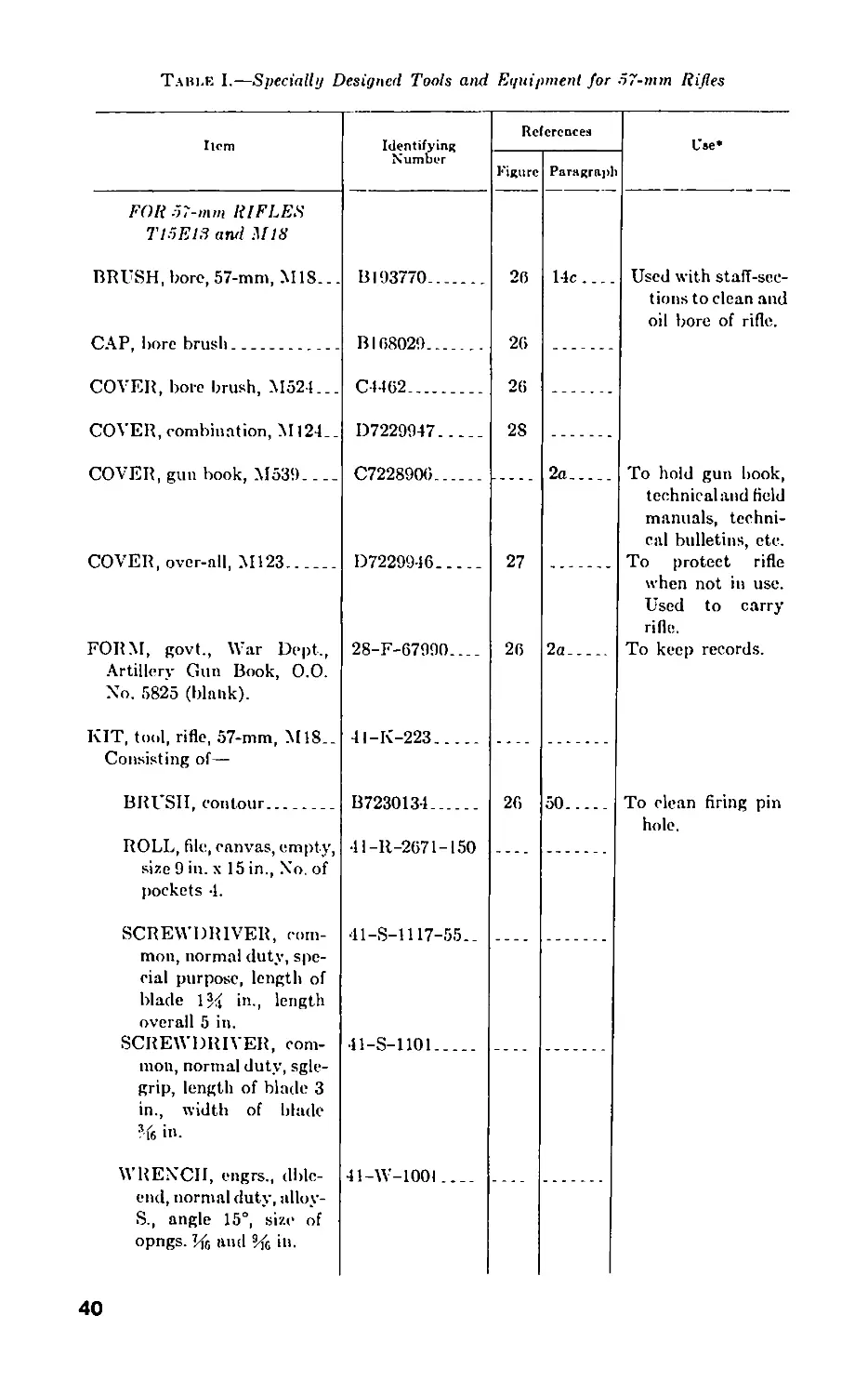
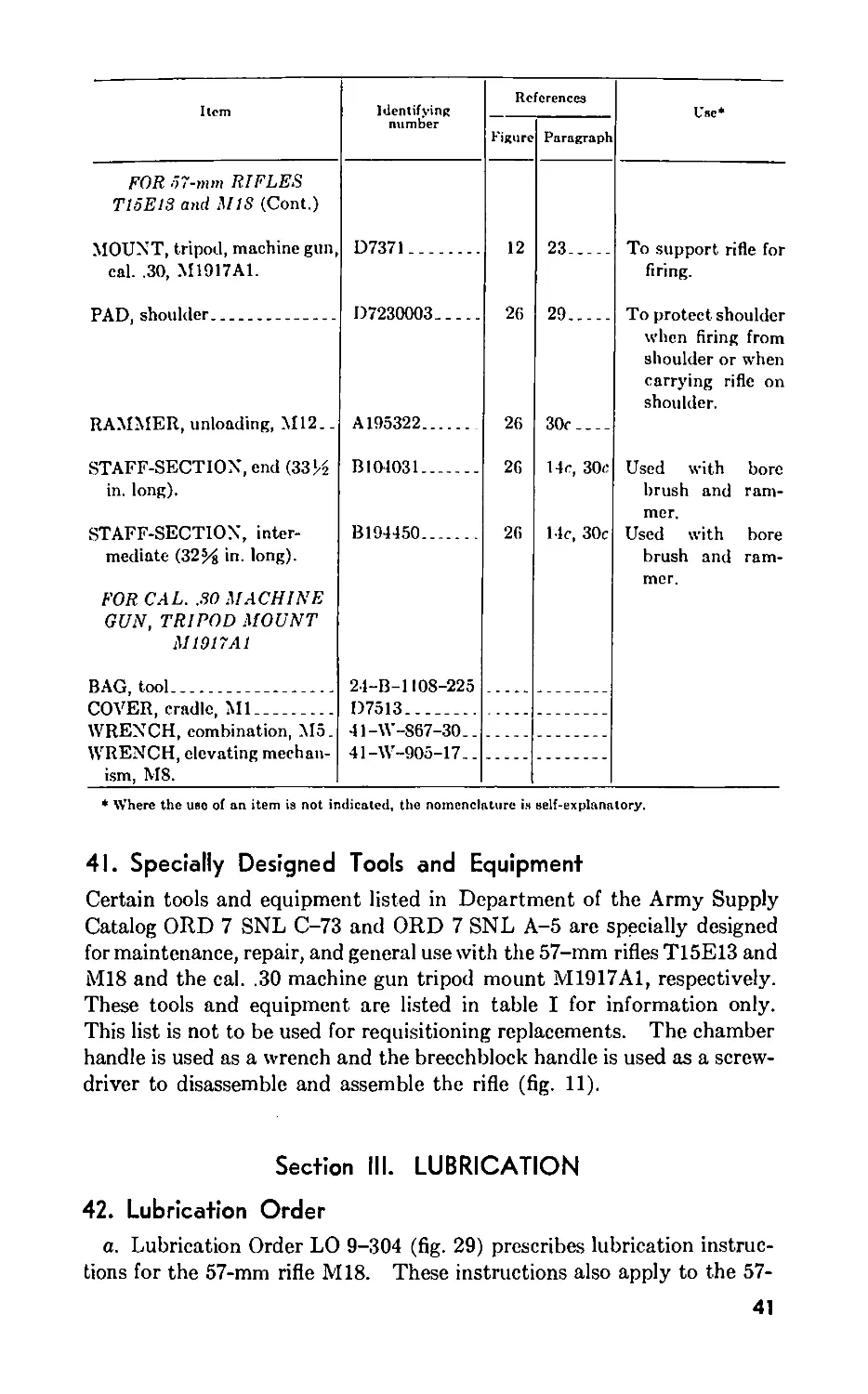
41. Specially Designed Tools and Equipment
Certain tools and equipment listed in Department of the Army Supply
Catalog ORD 7 SNL C-73 and ORD 7 SNL A-5 are specially designed
for maintenance, repair, and general use with the 57-mm rifles T15E13 and
M18 and the cal. .30 machine gun tripod mount M1917A1, respectively.
These tools and equipment are listed in table I for information only.
This list is not to be used for requisitioning replacements. The chamber
handle is used as a wrench and the breechblock handle is used as a screw-
driver to disassemble and assemble the rifle (fig. 11).
Section III. LUBRICATION
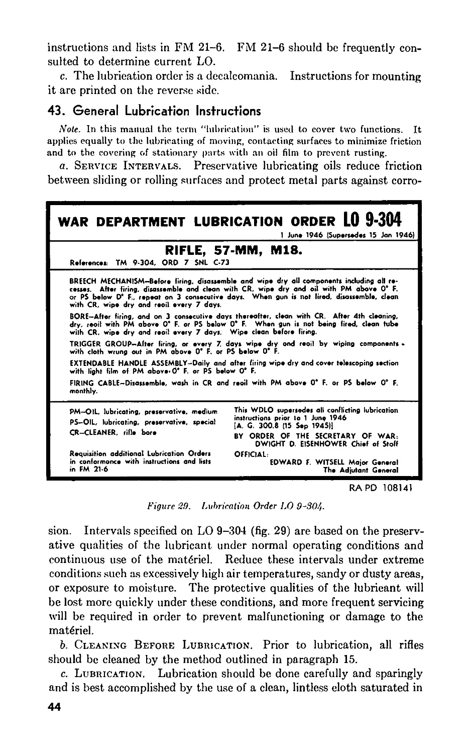
42. Lubrication Order
a. Lubrication Order LO 9-304 (fig. 29) prescribes lubrication instruc-
tions for the 57-mm rifle M18. These instructions also apply to the 57-
41
FORM—28-F-67990
BORE BRUSH
CAP—B168029
CONTOUR BRUSH—
B7230134
UNLOADING RAMMER
M12—A195322
I I ll 2 3
[inches | |
BORE BRUSH COVER.
M524—C4462
STAFFSECTION—ВЮ4031
STAFFSECTION—B194450
Figure 26. Equipment for 57-mm rifles.
RA PD 113394
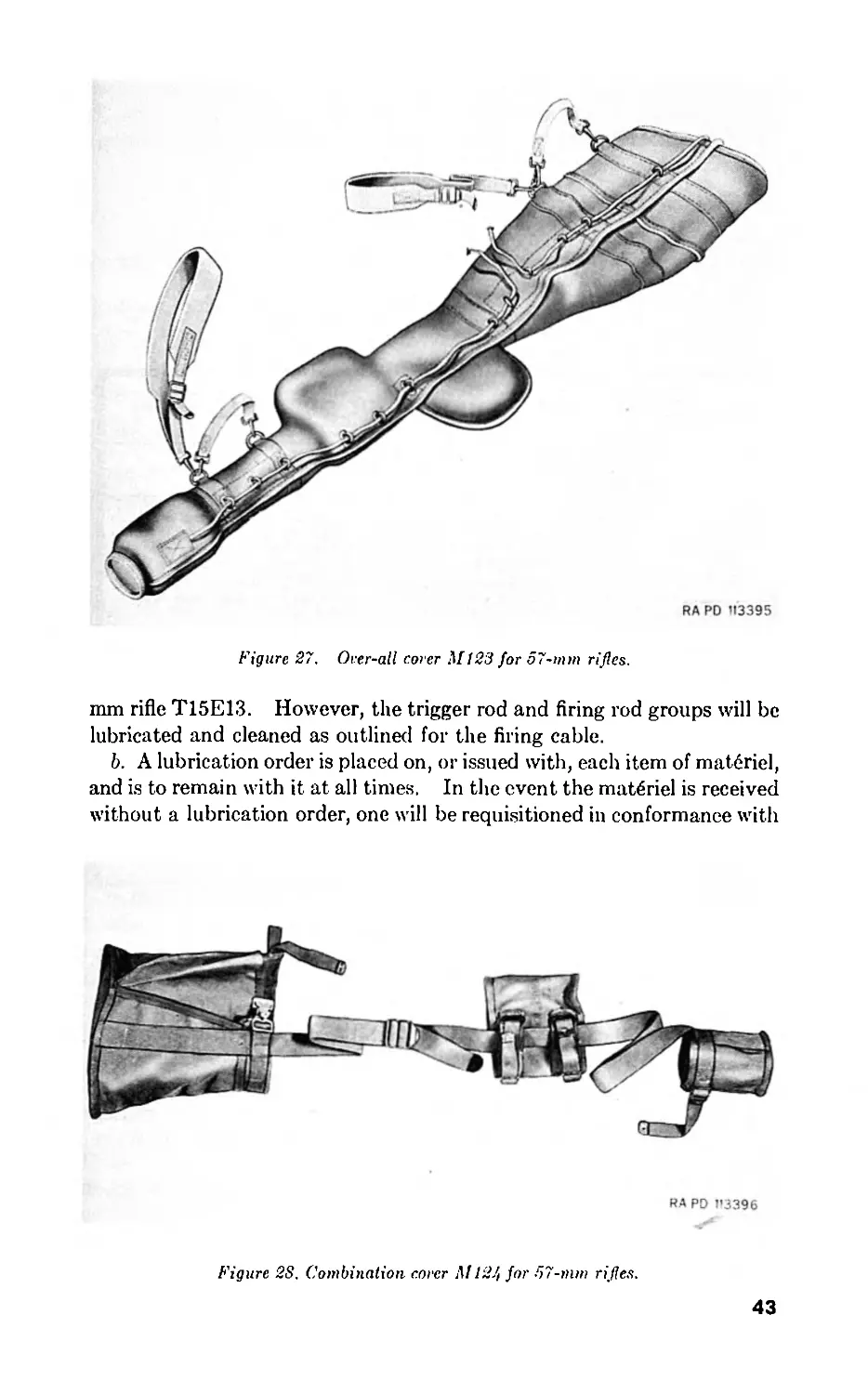
Figure 27. Over-all corer Ml 23 for 57-mm rifles.
mm rifle T15E13. However, the trigger rod and firing rod groups will be
lubricated and cleaned as outlined for the firing cable.
b. A lubrication order is placed on, or issued with, each item of matdriel,
and is to remain with it at all times. In the event the mat6riel is received
without a lubrication order, one will be requisitioned in conformance with
RA PD 1'3396
Figure 28. Combination corer M124 for 57-mm rifles.
43
instructions and lists in FM 21-6. FM 21-6 should be frequently con-
sulted to determine current LO.
c. The lubrication order is a decalcomania. Instructions for mounting
it are printed on the reverse side.
43. General Lubrication Instructions
Note. In this manual the term “lubrication" is used to cover two functions. It
applies equally to the lubricating of moving, contacting surfaces to minimize friction
and to the covering of stationary parts with an oil film to prevent rusting.
a. Service Intervals. Preservative lubricating oils reduce friction
between sliding or rolling surfaces and protect metal parts against corro-
WAR DEPARTMENT LUBRICATION ORDER LO 9-304
1 June 1946 (Supersedes 15 Jan 1946)
RIFLE, 57-MM, M18.
R.f.ronc.r TM 9-304, ORO 7 SNL C-73
BREECH MECHANISM-Before firing, disassemble and wipe dry all components including all re-
cesses. After firing, disassemble and clean wilh CR, wipe dry and oil with PM above 0е F.
or PS below 0е F., repeat on 3 consecutive days. When gun is not lired, disassemble, clean
with CR, wipe dry and reoil every 7 days.
BORE—After firing, and on 3 conseculive days thereafter, clean with CR. After 4th cleaning,
dry, reoil with PM above 0* F. or PS below 0* F. When gun is not being fired, clean tube
wilh CR. wipe dry and reoil every 7 days. Wipe clean before firing.
TRIGGER GROUP-After firing, or every 7. days wipe dry ond reoil by wiping components •
with cloth wrung out in PM above 0* F. or PS below 0° F.
EXTENDABLE HANDLE ASSEMBLY-Daily and after firing wipe dry and cover telescoping section
with light film of PM above* 0* F. or PS below 0* F.
FIRING CABLE-Disassemble, wash in CR and reoil with PM above 0* F. or PS below 0° F.
monthly.
PM—OIL, lubricating, preservative, medium
PS-OIL, lubricating, preservative, special
CR-CLEANER, rifle bore
Requisition additional Lubrication Orders
in conformonce with instructions and lists
in FM 21-6
This WDLO supersedes all conflicting lubrication
instructions prior Io 1 Jung 1946
[A. G. 300.8 (15 Sep 1945Ц
BY ORDER OF THE SECRETARY OF WAR:
DWIGHT D. EISENHOWER Chief of Stoff
OFFICIAL:
EDWARD F. WITSELL Major General
The Adjutant General
RAPD 108141
Figure 29. Lubrication Order LO 9-804-
sion. Intervals specified on LO 9-304 (fig. 29) are based on the preserv-
ative qualities of the lubricant under normal operating conditions and
continuous use of the matgriel. Reduce these intervals under extreme
conditions such as excessively high air temperatures, sandy or dusty areas,
or exposure to moisture. The protective qualities of the lubricant will
be lost more quickly under these conditions, and more frequent servicing
will be required in order to prevent malfunctioning or damage to the
mat6riel.
b. Cleaning Before Lubrication. Prior to lubrication, all rifles
should be cleaned by the method outlined in paragraph 15.
c. Lubrication. Lubrication should be done carefully and sparingly
and is best accomplished by the use of a clean, lintless doth saturated in
44
the proper lubricant and then wrung out. Excess oil should be wiped
off because it holds grit and foreign matter, which is conducive to exces-
sive wear of the moving parts. In addition, this may cause a malfunction.
Section IV. PREVENTIVE MAINTENANCE SERVICE
44. General
Preventive maintenance service prescribed by Army Regulations is a
function of the using organization. This section contains schedules of
organizational maintenance allocated to crew and battery or company.
Paragraph 45 contains important general preventive maintenance pro-
cedures. Special maintenance of specific groups of the rifle is covered,
when necessary, in sections pertaining to the groups. Special mainte-
nance for operation under unusual climatic conditions is covered in
paragraphs 32 through 36.
45. Common Procedures
The following general preventive maintenance will be observed in
addition to that referred to in the schedule in paragraph 48:
a. Corrosion, dirt, grit, contaminated oil, and water cause rapid de-
terioration of internal mechanisms and outer unpainted surfaces. Par-
ticular care must be taken to keep all bearing surfaces clean and properly
lubricated. Wiping cloths and cleaning materials are furnished for this
purpose. All traces of corrosion must be removed from unpainted sur-
faces with crocus cloth, which is the coarsest abrasive to be used for this
purpose.
b. Make certain that all screws and nuts are kept tightened and broken
parts replaced.
c. All burs or damaged surfaces on vital working parts, especially the
breech mechanism, must be attended to promptly because they may
develop to such a state as to affect operation or lead to malfunction in the
mechanism. Any burs or corrosion on bearing surfaces of mechanisms
that cannot be removed with crocus cloth must be reported to ordnance
maintenance personnel.
e. If paint has deteriorated or become damaged, exposing portions of
bare metal, the exposed portion must be repainted (par. 47). Sighting
and fire control equipment will not be painted by using personnel.
f. Repair without delay any loose grommets or rips in canvas covers;
failure to make immediate repairs may allow a minor defect to develop
into major damage. To prevent formation of damaging mildew, shake
out and air the canvas covers for several hours at frequent intervals.
Mildewed canvas is best cleaned by scrubbing with a dry brush. If
water is necessary to remove dirt, it must not be used until mildew has
8192330—49—4
45
been removed. Oil and grease can be removed by scrubbing with issue
soap and warm water. Rinse well with clean water and allow to dry.
Caution: At no time is gasoline or solvent to be used to remove oil
or grease spots from canvas.
For waterproofing of canvas, see TM 9-850.
g. Check tools, equipment, and spare parts for completeness (pars. 40
and 41). Replace missing items and turn in for repair all damaged items.
Use only tools that are provided and see that they are serviceable. Tools
that do not fit will fail or cause damage to parts. After use, items which
are susceptible to rust or corrosion must be thoroughly cleaned as outlined
in paragraph 15 and coated with a film of the1 oil prescribed in para-
graph 42.
h. Lettering on name plates and the lubrication order must be kept
legible and will not be painted over.
t. Check the current issue of FM 21-6 to determine whether all modi-
fications have been applied. If a modification has not been applied,
notify the local ordnance officer promptly. No alteration or modification
will be made except as authorized by modification work orders.
j. For gun book, see paragraph 2a.
46. Specific Procedures (Fig. 29).
a. Before Firing.
(1) Thoroughly wipe dry the bore and chamber of all dirt or oil,
using clean, dry jute burlap.
(2) Disassemble the breech mechanism (par. 58 or 65) and wipe dry
all components, including all recesses. Reassemble mechanism
(par. 59 or 66).
(3) Wipe outer surfaces of the rifle with clean, dry wiping cloth.
b. After Firing.
(1) Disassemble the breech mechanism (par. 58 or 65). Clean bore
and chamber and breech mechanism parts with rifle bore cleaner
as prescribed in paragraph 15. Reassemble mechanism (par.
59 or 66). Repeat this cleaning for three consecutive days
thereafter or until there is no longer any evidence of sweating,
which is caused by a chemical reaction of the burned powder
which cannot be removed by one cleaning. After the fourth
cleaning, if no firing is anticipated within the next 24 to 48
hours, thoroughly dry bore and chamber and all parts. Apply
a light film of the oil prescribed in paragraph 42.
(2) Wipe the trigger group and the extendible handle assembly dry
with clean, dry wiping cloth, and apply a light film of the oil
prescribed in paragraph 42.
(3) Wipe dry all screw and friction surfaces on the cal. .30 machine
gun tripod mount M1917A1 and reoil (par. 44).
c. Daily Service. Using clean, dry wiping doth, wipe the extendible
46
handle assembly dry, and cover telescoping section with a light film of the
oil prescribed in paragraph 42.
d. Weekly Service.
(1) Disassemble the breech mechanism (par. 58 or 65) and clean
with rifle bore cleaner as prescribed in paragraph 15. Wipe dry
and apply a light film of the oil prescribed in paragraph 42 to all
components and reassemble (par. 59 or 66).
(2) If the rifle is temporarily not in use, clean the bore and chamber
with rifle bore cleaner as outlined in paragraph 15. Wipe dry
and apply a light film of the oil prescribed in paragraph 42.
(3) Disassemble trigger group (par. 70 or 76) and wipe components
dry. Apply a light film of the oil prescribed in paragraph 42 to
all components and reassemble (par. 71 or 77).
(4) Wipe dry all screw and friction surfaces on the cal. .30 machine
gun tripod mount M1917A1 and reoil (par. 44).
e. Monthly Service. Disassemble firing cable (rifle M18) (par. 70)
or trigger and firing rods (rifle T15E13) (par. 76) and thoroughly clean as
outlined in paragraph 15. Wipe dry and apply a light film of the oil
prescribed in paragraph 42. Reassemble as outlined in paragraph
71 or 77.
f. Service for Periods Up To 90 Days. If it is anticipated that
the rifle will not be used for a period up to 90 days, and neither lubrication
every 7 days nor placing the mat6riel in limited storage (par. 3, app. I)
is desirable, the rifle may be coated with preservative lubricating oil
(medium), regardless of temperatures. This is applied by dipping the
rifle components into a bath of the oil. Frequent inspections will be
made to determine that the oil film is adequate to prevent corrosion. If
corrosion is present, clean by one of the methods outlined in this section.
Thoroughly inspect rifle, paying particular attention to unexposed sur-
faces such as the bore and chamber, springs and spring seats, firing pin,
and like places where corrosion might occur and not be quickly noticed.
Remove any corrosion with crocus cloth and reoil.
47. Painting
Painting is necessary to preserve the outside surfaces of the rifle from
corrosion. Use olive drab, synthetic, lustreless enamel. In an emer-
gency, preservative lubricating oil (medium) may be used as a temporary
expedient to prevent corrosion. Painting also prevents light reflection
from worn spots which have become shiny. Polished parts, or moving
parts where wear occurs and where functioning may be affected by appli-
cation of paint, should not be painted. Corrosion should be removed
where present, the parts cleaned, and then painted for protection against
further corrosion. Painting should be done with the utmost care, and
application of paint strictly limited to the damaged area. Care should be
observed that no paint penetrates to other parts of the gun, or is so
applied that it may be rubbed off and cause clogging of the mechanism.
47
48. Maintenance Schedule
The items or points to be inspected and serviced at scheduled times
are listed below with cross references to pertinent instructions covered
in other sections.
Point Prerentive Maintenance Detailed Indtructiona
DAILY SERVICE
Extendible handle assembly........Clean and oil........Par. 46c.
BEFORE FIRING
Bore and chamber..................Wipe dry______________Par. 46a(l).
Breech mechanism__________________ Wipe dry_____________Par. 46a(2).
Outer surfaces____________________ Wipe dry____________ Par. 46a(3).
AFTER FIRING
Bore and chamber and breech mecha- Clean and oil__________Par. 46b(l).
nism.
Trigger group and extendible handle Clean and oil_________Par. 46b(2).
assembly.
Cal. .30 machine gun mount M1917A1. .Clean and oil________Par. 46h(3).
WEEKLY SERVICE
Bore and chamber_________________ Clean and oil______
Breech mechanism_________________ Clean and oil.......
Trigger group-------------------------
Locating surfaces and external un-
painted metal surfaces, including all
sighting and fire control instruments.
Exposed surfaces of all lenses........
Cal. .30 machine gun mount M1917A1
Clean and oil________
Clean and oil.......
Clean________________
Clean and oil........
Par. 46d(2).
Par. 46d(l).
Par. 46d(3).
Wipe surfaces clean
and renew oil
film.
Par. 97c.
Par. 46d(4).
MONTHLY SERVICE
Trigger rod and firing rod groups (rifle
T15E13) and firing cable (rifle M18).
Eye shields of telescopes_____________
Clean and oil_________Par. 46e.
Clean and dust________Clean with soap and
water, dry, and
dust with talc.
Muzzle and breeeh
Hammer
BEFORE TRAVELING
Protect
INACTIVE PERIODS
Place hammer in the
“as fired” position.
Make sure the rifle
is not loaded. Se-
cure proper cov-
ers in place.
Par. 16e.
48
Section V. MALFUNCTIONS AND CORRECTIONS
49. General
It is important that the rifle and all its equipment be properly installed
and maintained. Proper care of the rifle and attention to preventive
maintenance schedules (par. 48) will greatly reduce the possibility of
stoppages due to malfunctions.
50. Failure to Fire
a. In the event that the cartridge is not fired when the trigger is
squeezed, remove the cartridge, observing precautions given in paragraph
31. If the primer is not indented or only slightly indented, disassemble
the breech mechanism (pars. 58, 65, and 70), and inspect for broken firing
pin, weak or broken firing spring, broken safety spring, or accumulated
powder fouling on the firing pin shoulder or in the firing pin recess. If
firing pin hole is dirty, clean with contour brush.
b. Replace defective firing pin, firing spring, or safety spring, and
thoroughly clean all powder fouling from the firing pin and its recess and
assemble (pars. 59, 66, and 71).
51. Failure to Extract
a. Failure to extract is generally caused by a worn or broken extractor
assembly or weak, broken or fouled extractor spring.
b. Clean fouled spring and replace defective components (pars. 58 and
65).
52. Movement of Rifle Rearward
In most eases new rifles will have a slight rearward movement. This
movement will stop after approximately 100 rounds have been fired due
to erosion of the orifices.
53. Movement of Rifle Forward
a. A forward movement of the rifle is caused by excessive erosion of
the orifices.
b. When there is an excessive forward thrust of the rifle when firing
from the shoulder, strong enough to pull the rifle off the target, the rifle
should be rebalanced by replacing the throat ring and throat blocks as
outlined in paragraph 83.
49
Section VI. BREECH MECHANISM (RIFLE Ml8)
54. General
a. The breech mechanism permits the opening of the breech for the
insertion of a round of ammunition. The round is locked in place when
the breech is closed for firing.
b. The breech mechanism comprises a breechblock for closing the
breech end of the chamber; a breechblock carrier assembly for supporting
the breechblock while swinging to the open or closed position; and a
breechblock handle which is used to rotate the breechblock when opening
to unlock, or closing to lock the breech (fig. 11).
55. Functioning
a. The breechblock handle, when actuated, rotates the breechblock
around the breechblock carrier assembly. This turning unlocks or locks
the interrupted lugs on the breechblock from the mating interrupted lugs
in the chamber.
b. As the breechblock is swung closed, the notch in the extractor rides
over and engages the rim of the cartridge ease. As the breechblock is
swung open, the cartridge case is extracted.
c. The firing pin hammer has two cam surfaces on its forward end which
mate with similar cam surfaces in the firing pin bushing which is assembled
to the breechblock.
d. With the breechblock closed and locked, counterclockwise rotation
of the breechblock allows the cocking cams on the firing pin bushing to
engage the cams on the hammer and force the hammer to the rear, com-
pressing the firing spring. The hammer is retained in the rearward posi-
tion by the tops of the cocking cams on the firing pin bushing when the
breechblock is unlocked.
e. The rotation of the breechblock is automatically stopped after the
interrupted lugs are disengaged, about 45° rotation, by the action of the
breechblock contacting the breechblock carrier. The breechblock is re-
tained in the unlocked position by the engagement of the breechblock
detent in the breechblock cover.
f. The breech is opened, after the breechblock contacts the carrier, by
grasping the breechblock handle and swinging the breechblock to the rear.
The breech is closed by swinging the breechblock forward into the
chamber.
g. As the breechblock is rotated to the locked position, the hammer
moves off the top of the cocking cams on the firing pin bushing and moves
forward until retained by the sear. This action is accomplished in about
5° rotation. When closed, the breechblock is securely locked to the
chamber by the; engagement of the interrupted lugs. The breechblock is
locked in the closed position by the engagement of the breechblock detent
with the breechblock cover. The breechblock detent is a spring actuated
50
Figure SO. Safety lever removed—rifle MIS.
lock, and it engages the breechblock cover whenever the breechblock is in
the locked or unlocked position. The breech may be opened while the
firing pin hammer remains cocked, by rotating the breechblock handle,
since the detent does not form a positive lock.
Warning: Never stand or permit any portion of the body to be
directly behind the rifle when opening or closing the breech with live
ammunition in the chamber.
56. Removal of Breech Mechanism (Rifle Ml8)
a. Open breech and unscrew and remove breechblock handle (fig. 11).
b. Turn safety lever in counterclockwise direction until clear of safety
lever retaining pin and withdraw lever from the breechblock carrier pivot
(fig. 30).
c. Push and hold safety spring toward chamber and, using screwdriver
end of breechblock handle as a tool, push breechblock carrier pivot out
of carrier hinge bracket (fig. 31). Release safety spring.
Figure 31. Removing breechblock carrier pivot—rifle M18.
d. Withdraw breech mechanism from carrier hinge bracket assembly
(fig- 32).
57. Installation of Breech Mechanism (Rifle Ml8)
a. Insert breechblock carrier assembly in carrier hinge bracket, aline
hole in hinge with hole in bracket, and insert breechblock carrier pivot,
small end leading, until stopped by safety spring (fig. 33). Push and
hold safety spring toward chamber to clear pivot and push pivot com-
pletely into bracket, making sure that the slot in pivot straddles the pin
(fig. 34). Release safety spring.
52
BREECHBLOCK
BREECHBLOCK
CARRIER ASSEMBLY
BREECH MECHANISM
CARRIER HINGE BRACKET ASSEMBLY
RAPD 107749
Figure 82. Breech mechanism removed from carrier hinge bracket—rifle M18.
m
Ы
BREECHBLOCK CARRIER PIVOT - В 7230753
RAPD 109094
Figure 33. Inserting breechblock carrier pivot until stopped by
safety spring—rifle MIS.
SAFETY SPRING-A 7230354
BREECHBLOCK
BREECHBLOCK
CARRIER ASSEMBLY
RAPD 109095
Figure 3/t. Sealing breechblock carrier pirot while holding safety
spring—rifle M18.
54
b. With breech open, insert safety lever in carrier pivot. Turn lever
clockwise as far as possible, making sure that flange on lever is retained
by the head of the safety lever retaining pin (fig. 30).
c. Replace breechblock handle and close breech.
58. Disassembly of Breech Mechanism (Rifle Ml8)
a. Remove breech mechanism from chamber (par. 56).
b. Remove breechblock detent screw (fig. 11).
c. Unscrew the three breechblock cover screws and raise the breech-
block cover high enough to rotate the breechblock detent from under the
cover. Rotate detent from under cover (fig. 35), allow cover to drop in
place, and unhook detent from pin. Secure cover in place with the three
screws.
d. Holding breechblock in left hand, face down, rotate carrier assembly
counterclockwise (fire position) (fig. 36). Using screwdriver end of
breechblock handle, actuate sear lever by pushing down to disengage
sear from hammer and relieve pressure of compressed firing spring (fig.
37). Remove breechblock cover screws and breechblock cover.
e. The breechblock carrier assembly may be held down by hand rather
than by the breechblock cover and cover screws as stated in c and d above.
However, the carrier must be held down securely when the sear is dis-
engaged from the hammer (fig. 37).
f. Lift carrier assembly out of breechblock. Withdraw firing pin from
its recess in the center of the firing pin bushing.
g. Using the thumb, actuate the sear lever enough to allow the firing
pin hammer and firing pin spring to drop out of their recess in the carrier
assembly (fig. 38). The new type striker assembly for the rifle M18 com-
bines a firing pin hammer and firing pin, and replaces the old type separate
firing pin hammer and firing pin (fig. 40). The striker assembly is dis-
assembled by removing the spring pin.
h. Unscrew and remove sear plug and withdraw sear spring (fig. 39).
?. Unscrew and remove sear lever axis pin and withdraw sear lever and
sear (fig. 39).
j. Unscrew extractor retaining plug and remove extractor spring and
extractor assembly (fig. 41).
k. Unscrew and remove throat block screws and remove top and bottom
throat blocks (fig. 41).
Note. Throat blocks must be placed back in same positions on reassembly.
I. Unscrew and remove the two firing pin bushing and throat ring re-
taining screws and withdraw throat ring from its seat (fig. 42).
Note. Some throat rings have three screws.
59. Assembly of Breech Mechanism (Rifle Ml8)
a. Place throat ring in its recess in front face of breechblock, making
sure that the hole for the extractor is on the extractor side, and secure
55
сл
о
Figure 35. Removing breechblock detent from breech mechanism—rifle Mt 8.
Figure 36. Rotating carrier assembly to fire position.
in
co
SEAR PLUG - A 7230346
BREECHBLOCK
RAPD 107752
BREECHBLOCK CARRIER ASSEMBLY
Figure 37. Actuating sear lever to disengage sear from hammer—rifle M18.
сл
-о
Figure 38. Actuating sear lever with thumb to allow firing pin hammer and firing spring to drop out of
carrier assembly—rifle Ml 8.
о
о
BREECHBLOCK CARRIER
ASSEMBLY
Figure 39. Breechblock carrier group—exploded view—rifle M18.
or—0EEZGI8
FIRING PIN HAMMER
FIRING PIN
FIRING PIN
STRIKER ASSEMBLY
OLD TYPE
NEW TYPE
RA PD 113378
SPRING PIN
o
Идите !,(). Striker assembly (new type) and firing pin and firing pin hammer (old type)—rifle M18.
(EXTRACTOR Л i
A7i •
EXTRACTOR SPRING
1А7230370 Ml 8
(A7229325 T1 TH 1
BREECHBLC" К AS Y
FIRING PIN
A7230435
XTRACTOR RETAINING PLUG
IA723O369 'MIS' I
IA722932T TiSEH'l
RAPD 107996
Figure 41. Extractor group reinored from breechblock.
with the two (or three) firing pin bushing and throat ring retaining screws
(fig. 42). Do not tighten the screws prior to assembling the extractor
assembly.
b. Place top and bottom throat blocks on breechblock and secure with
throat block screws. These screws should be tightened and then backed
Figure 42. Throat ring and throat blocks reinored from breechblock.
RA PD 107997
62
off one-quarter to one-half turn from the tight position; otherwise, they
will be extremely difficult to remove after firing. Also, the breechblock
will be difficult to open after firing a round, since the gas pressure between
the throat blocks and the throat ring moves the throat blocks against the
chamber. Make sure bottom throat block, which has extractor relief cut,
is on extractor side.
SEAR PLUG-A 7230346
EXTRACTOR RETAINING PLUG -A7230369
RAPD 107757
Figure 48. Sear plug and extractor retaining plug—rifle MIS.
c. Insert extractor assembly, claw end leading, and extractor spring
(fig. 41) in their recess in rear face of breechblock so that the guide stud
on extractor is engaged in its slot in the breechblock. Secure in place
by inserting extractor retaining plug and screwing flush with breechblock.
Tighten the firing pin bushing and throat ring retaining screws.
Caution: Care must be exercised to make sure that the extractor
retaining plug is not confused with the sear plug, for, although they are
of the same thread diameter, they are not interchangeable.
Figure 43 illustrates the extractor retaining plug and the sear plug for
the rifle M18.
63
(/. Place firing pin in its seat in the center of the breechblock (fig. 41).
If new type striker assembly is used, assemble firing pin and firing pin
hammer with spring pin (fig. 40).
c. Insert sear in its recess in carrier (fig. 39) so that the headed end is at
the bottom and the narrow milled shoulder, on the opposite end, is to the
rear. Figure 44 illustrates these surfaces.
f. Engage sear lever with sear so that the forked end engages the milled
cuts on the headed end of sear. Aline hole in sear lever with the hole in
the carrier. Insert and tighten sear lever axis pin. Insert sear spring
in its recess behind the sear and retain in place by inserting and tightening
sear plug (fig. 39). Note caution in c above.
<j. Using the thumb, actuate the sear lever enough to withdraw the sear
out of hammer opening in the carrier. Insert the firing spring and firing
pin hammer (or new type striker assembly), and release the sear lever to
allow sear to retain firing spring and firing pin hammer in place.
h. Engage the hooked end of breechblock detent on its pin in carrier
(fig. 35), and secure in place by inserting the breechblock detent screw
through the detent into the back of carrier.
i. Place carrier group in the recess in rear of breechblock so that the
“V” shaped cam surfaces on hammer are resting in the “V” shaped
notches in the center of the breechblock.
j. Place breechblock cover over the circular portion of the carrier which
houses the hammer, making sure that the holes which engage the detent
are facing the breechblock. Aline detent hole in the cover with the detent
and aline the three cover screw holes with the mating holes in breechblock.
Place the three cover screws through the cover and screw them into the
breechblock.
k. Holding breechblock with left hand, rotate carrier assembly clock-
wise, thereby cocking the hammer (fig. 45). This also places the breech
mechanism in position to be assembled to the chamber.
I. Assemble breech mechanism to chamber (par 57).
60. Maintenance of Breech Mechanism
a. Examine; interrupted lug on breechblock for burs. If burs are
present, notify ordnance; personnel.
b. Remove any corrosion present with crocus cloth.
c. Replace the extractor spring, firing spring, or sear spring if weak,
distorted, corroded, or broken.
d. Examine hammer and carrier assemblies for burs or corrosion. .Re-
move any burs or corrosion present with crocus cloth. See paragraph
45 c for removal of burs on bearing surfaces.
e. If the lip of the narrow milled shoulder of the sear (fig. 44) which
engages the hammer exhibits any significant bevel, the sear should be
replaced. Since the hammer spring is much stronger than the sear
spring, any significant bevel between the engaging surfaces of the sear
64
о
U1
Figure 45. Cocking the hammer.
RA PD 107759
and hammer may allow the force of the hammer spring to overcome the
force of the sear spring and allow the hammer to fall.
f. Using the method of cleaning outlined in paragraph 15, thoroughly
clean all powder residue or dirt from all components in the breech mecha-
nism and apply a light film of oil specified in paragraph 42.
Section VII. BREECH MECHANISM (RIFLE TI5EI3)
61. General
See paragraph 54.
62. Functioning
See paragraph 55.
63. Removal of Breech Mechanism (Rifle TI5EI3) (fig. 46)
«. Open breech and unscrew and remove breechblock handle. Unscrew
and remove carrier pivot, using the screwdriver end of breechblock handle.
b. Withdraw breech mechanism from the carrier hinge bracket assem-
bly.
64. Installation of Breech Mechanism (Rifle TI5EI3) (fig. 46)
a. Insert breechblock carrier assembly in the carrier hinge bracket and
secure by inserting and tightening the carrier pivot.
b. Replace breechblock handle and close breech.
65. Disassembly of Breech Mechanism (Rifle TI5EI3)
a. Remove breech mechanism from chamber (par. 63).
b. Holding breechblock in left hand, face down, rotate the carrier
assembly counterclockwise (fire position) (fig. 35). Using thumb, ac-
tuate sear lever to disengage sear from hammer and relieve pressure of
compressed firing spring.
c. Remove breechblock cover screws and breechblock cover. Lift
carrier assembly out of breechblock. Withdraw firing pin from its recess
in the center of breechblock.
<1 . Using the thumb, actuate the sear lever enough to allow the firing
pin hammer and firing spring to drop out of their recess in the carrier
assembly. (Figure 38 shows the similar operation for the rifle M18.)
e. Unscrew' breechblock detent screw' and remove breechblock detent
from breechblock carrier assembly (fig. 47).
f. Unscrew' and remove sear plug and withdraw sear spring (fig. 47).
g. Unscrew' and remove sear lever axis pin and withdraw sear lever
and sear (fig. 47).
66
BREECH MECHANISM
RAPD 107746
Figure 46. Idreech mechanism removed from chamber—rifle TlliElS.
о
со
SEAR LEVER AXIS PIN'X
BREECHBLOCK DETENT
SEAR PLUG
INCHES
RA PD 113379
h. Unscrew extractor retaining plug and remove extractor spring and
extractor assembly (fig. 41) from rear face of breechblock.
i. Unscrew and remove throat block screws and remove top and bot-
tom throat blocks (fig. 42) from front face of breechblock.
j. Unscrew and remove the two firing pin bushing and throat ring re-
taining screws and withdraw throat ring from its seat (fig. 42).
Note. Some throat rings have three screws.
66. Assembly of Breech Mechanism (Rifle TI5EI3)
a. Place throat ring in its recess in the front face of breechblock, making
sure that the hole for the extractor is on the extractor side, and secure with
the two (or three) firing pin bushing and throat ring retaining screws (fig.
42). Do not tighten the screws prior to assembling the extractor assem-
bly.
b. Place top and bottom throat blocks on the breechblock and secure
with throat screws. These screws should be tightened and then backed
off one-quarter to one-half turn from the tight position, otherwise, they
will be extremely difficult to remove after firing. Also, the breechblock
will be difficult to open after firing a round, since the gas pressure between
the throat blocks and the throat ring moves the throat blocks against the
chamber. Make sure that the bottom throat bloek, which has extractor
relief cut, is on the extractor side.
c. Insert extractor assembly, claw end leading, and extractor spring
(fig. 41) in their recess in the rear face of breechblock so that the guide
stud on the extractor is engaged in its slot in the breechblock. Secure
in place by inserting extractor retaining plug and screwing flush with
breechblock. Tighten the firing pin bushing and throat ring retaining
screws.
Caution: Care must be exercised to make sure that the extractor
retaining plug is not confused with the sear plug, for, although they are
of the same thread diameter, they are not interchangeable.
Figure 48 illustrates the extractor retaining plug and the sear plug for
the rifle T15E13.
d. Place firing pin in its seat in the center of the breechblock (fig. 41).
e. Insert sear in its recess in carrier (fig. 47) so that the headed end is
at the bottom and the narrow milled shoulder, on the opposite end, is to
the rear. Figure 44 illustrates these surfaces. Note paragraph 60e.
f. Engage sear lever with sear so that the forked end of the sear lever
engages the milled cuts on the headed end of the sear.
(1) The T15E13 rifle may have either of two types of sear levers.
One type of sear lever is illustrated in figure 47. The other type
is similar in shape but has an adjusting screw on the surface of
the sear lever which engages the bellcrank. The adjusting
screw is a socket-head set screw with a rounded point. The
adjusting screw is locked in the sear lever with a flat point
69
socket-head set screw. The function of the adjusting screw Ls
to reduce the slaek in the firing linkage. The adjusting screw
should protrude from the rounded end of the sear lever only
enough to provide the proper linkage adjustment so that the
sear lever moves the sear out of engagement with the firing
hammer when the trigger is pulled. The sear lever is symmet-
rical along its longitudinal axis. If the sear lever has the ad-
justing and locking screws, care must be exercised in assembling
the sear lever to the carrier so that the rounded point of the ad-
justing screw and not the flat head of the locking screw will
engage the bellcrank.
(2) Aline the hole in the sear lever with the hole in the carrier.
Insert and tighten the sear lever axis pin.
(3) Insert the sear spring in its recess behind the sear and retain in
place by inserting and tightening sear plug (fig. 47). Note
caution in c above.
SEAR PLUG-A 7229358
EXTRACTOR RETAINING PLUG-
A 7229324
RAPD 107993
Figure 48. Sear plug and extractor retaining plug—rifle T15E13.
g. Assemble breechblock detent to the carrier assembly and secure in
place with the breechblock detent screw.
h. Using the thumb, actuate the sear lever enough to withdraw the
sear out of the hammer opening in the carrier. Insert the firing spring
and firing pin hammer into the opening and release the sear lever to allow
sear to retain firing spring and firing pin hammer in place.
i. Place carrier group in the recess in the rear of breechblock so that
the “V” shaped cam surfaces on hammer are resting in the “V”-shaped
notches in the center of the breechblock.
j. Place breechblock cover over the circular portion of the carrier which
houses the hammer, making sure that the holes which engage the detent
are facing the breechblock. Aline the detent hole in the cover with the
70
detent and aline the three cover screw holes with the mating holes in
breechblock. Place the three cover screws through the cover and screw
them into the breechblock.
k. Holding breechblock with left hand, rotate the carrier assembly
clockwise, thereby cocking the hammer (fig. 45). This also places the
breech mechanism in position to be assembled to the chamber.
I. Assemble breech mechanism to chamber (par. 64).
67. Maintenance of Breech Mechanism
See paragraph 60.
Section VIII. TRIGGER GROUP (RIFLE Ml8)
68. General
a. The trigger group, when actuated with the hammer in the cocked
position, permits the release of the compressed firing spring, thereby
driving the hammer forward to strike the firing pin which indents the
primer of a round of ammunition.
b. The trigger group is composed of a trigger handle group and a firing
cable group.
c. The trigger handle group is secured to the tube by a bracket. It
houses the trigger, trigger safety assembly, firing cable operating link,
trigger grips, and extendible handle assembly.
d. The firing cable group extends along the outside of the rifle, its front
end being housed in the trigger handle group and its rear end in the carrier
hinge bracket.
69. Functioning
a. The trigger safety engages and prevents the firing cable operating
link from being actuated by the trigger until the trigger safety is depressed.
When the trigger safety is depressed, it rotates its arm out of engagement
with the firing cable operating link. As the trigger is squeezed, it actuates
the firing cable operating link. The link engages the firing cable end and
forces the firing cable forward (toward the muzzle), compressing the
firing cable return spring. Attached to the rear end of the firing cable
is a safety spring which engages the sear lever. As the firing cable is
forced forward, the safety spring engages and rotates the sear lever about
the sear lever axis pin. The forked end of the sear lever, which is en-
gaged with the sear, forces the sear out of engagement with the hammer.
This allows the compressed firing spring to expand, forcing the hammer
forward to strike the firing pin. When the trigger is released, the com-
pressed firing cable return spring expands and returns the component
parts of the trigger group to their original position. When the safety
lever is in the “safe” position, it cams the safety spring out of engagement
with the sear lever.
71
КЗ
TRIGGER HANDLE BODY
QUALIFYING MARKS
RA PD 113380
RIGHT HAND TRIGGER HANDLE GRIP
LEFT HAND TRIGGER HANDLE GRIP
TRIGGER HANDLE GRIP SCREW
Figure .tf. Trigger handle grips—exploded view.
b. The extendible handle assembly is held with the left hand to help
support the rifle when firing from the shoulder. It is also used as a front
support for the rifle when firing from the bipod. Its height, can be ad-
justed by pulling the extendible! handle extension out of the housing and/
or by turning the threaded extendible handle sleeve (par. 24d).
70. Disassembly of Trigger Group (Rifle Ml8)
a. Remove breech mechanism from chamber as outlined in paragraph
56.
b. Using screwdriver end of breechblock handle, unscrew the trigger
handle grip screws and remove the left- ami right-hand trigger handle
grips (fig. 49).
c. Unscrew and remove the pivots which secure the trigger, the trigger
safety, ami the firing cable operating link. Withdraw trigger, trigger
safety, and firing cable operating link from t heir seats in the trigger handle
body (fig. 50).
Figure Trigger handle budg grnup ridt .\l IS—exploded rieir.
d. Disengage firing cable end from the firing cable1 by unscrewing
clockwise. Remove firing cable end from the hole in the trigger handle
clamp (fig. 51).
e. Unscrew and remove the firing cable lock screw (fig. 52).
f. Remove firing cable assembly by grasping the safety spring and
pulling it to the rear (fig. 53).
73
able end re „ne ed fron, trigger hnntIle rla,np-rifle yns
74
g. Detach firing cable return spring from the firing cable guide and
withdraw it from cable (fig. 5'1).
h. Remove safety spring from the firing cable guide by driving out the
firing cable guide pin. This pin should bo driven from the slotted side
of the guide (fig. 55).
i. Remove the trigger safety spring from the trigger safety by sliding
it sideways out of its seat (fig. 56).
j. Remove the carrier hinge bracket bottom cover spring by removing
the two retaining screws (fig. 52).
FIRING CABLE LOCK SCREW-A7230388
CARRIER HINGE BRACKET BOTTOM COVER SPRING
CARRIER HINGE BRACKET BOTTOM COVER SPRING RETAINING
SCREW-A 7229361
RAPD 107760
Figure 52. Carrier hinge bracket group—rille .1/IS—exploded rieir.
71. Assembly of Trigger Group (Rifle Ml8)
a. Insert shank of the safety spring into the slot of the firing cable guide
so that the slot in the spring is on the same side as the slot in the guide.
Secure safety spring to the guide by inserting the guide pin. This pin
should be inserted through the countersunk side of the hole in the guide
and should not protrude into the slot nor should it protrude outside of
the guide (fig. 57).
b. Assemble carrier hinge bracket bottom cover spring to carrier hinge
bracket with two retaining screws (fig. 52).
75
firing cable return spring a
FIRING CABLE GUIDE
CHAMBER
HINGE BRACKET ASSEMBLY
RAPD 107765
CABLE
- А723О35-Г
Figure 53. Removing firing cable assembly—rifle M18.
FIRING CABLE GUIDE
RAPD 107766
Figure 54. Removing firing cable return spring—rifle M18.
c. Assemble firing cable return spring over the firing cable and seat the
spring onto the guide (fig. 54).
d. Insert firing cable assembly, cable end leading, through the carrier
hinge bracket and into the firing cable conduit. Aline the slot in the guide
with the pin in the bracket and push the guide into the bracket until
stopped by the firing cable return spring (fig. 53).
e. Insert firing cable operating link into the trigger handle body so that
one end of the link extends toward the firing cable. Secure in place by
inserting and tightening the pivot (fig. 50).
f. Insert firing cable end in its hole in the front end of the trigger handle
clamp and screw onto the firing cable by turning counterclockwise (fig. 51).
g. Insert trigger in position in the trigger handle body and secure with
the pivot (fig. 50).
h. Aline circular end of the trigger safety spring with its hole in the
trigger safety (fig. 56). Assemble spring to the trigger safety. Install
trigger safety assembly into the trigger body and secure with the pivot
(fig. 50).
i. Assemble right- and left-hand trigger handle grips to the trigger
body and insert and tighten the four screws (fig. 49).
j. Depress trigger safety and squeeze the trigger, thereby moving the
firing cable, until the slot in firing cable guide alines with the firing cable
lock screw hole. Holding trigger to maintain this alinement, insert and
tighten the lock screw (fig.52).
k. Assemble breech mechanism to the chamber as outlined in paragraph
57.
8192330—49—6
77
N
00
RAPD 107767
Figure 55. Removing safety spring from firing cable guide—rifle At 18.
72. Adjustment of Trigger Group (Rifle Ml8)
a. Examine the qualifying marks on the bracket section of the trigger
handle body to make sure that they aline with the qualifying marks on the
tube (fig. 50). If they do not aline, loosen the two trigger handle bolt
nuts and the front firing cable conduit lock bolt nut (fig. 50) and move
trigger handle body until qualifying marks on tube and body are alined.
Caution: Make certain a round of ammunition is not in the chamber.
Figure 56. Trigger safely assembly—rifle MIS—exploded view.
b. With the rifle cocked and the safety lever in the fire position, de-
press the trigger safety and squeeze the trigger. If the hammer does
not release, screw the firing cable end, either clockwise or counterclock-
wise, until the hammer does release when the trigger is actuated.
c. If the trigger cannot be pulled after the trigger safety has been de-
pressed, turn the firing cable end clockwise until the trigger can be pulled
and the hammer released.
d. If, when the trigger safety is depressed and the trigger is squeezed,
the hammer is not released and the trigger has no spring action, turn the
firing cable end counterclockwise until the trigger has a definite spring
action and the hammer is released.
79
73. Maintenance of Trigger Group (Rifle Ml8)
a. After approximately each 100 rounds of ammunition has been fired,
or at least once a month, the trigger group will be completely disassembled
(par. 70), cleaned (par. 15), lightly oiled (par. 42), and reassembled (par.
71). Particular attention will be given to see that the inside of the firing
cable conduit is thoroughly cleaned.
b. Replace the safety spring if it is fractured or deformed (pars. 70 and
71).
c. Replace the firing cable return spring if it is weak or fractured (pars.
70 and 71). Thoroughly remove all powder fouling or dirt.
d. Remove any corrosion present with crocus cloth.
e. Examine all components for burs, removing any present by using
crocus cloth. See paragraph 45c for removal of burs on bearing surfaces.
Section IX. TRIGGER GROUP (RIFLE TI5EI3)
74. General
a. The trigger group, when actuated with the hammer in the cocked
position, permits the release of the compressed firing spring, thereby
driving the hammer forward to strike the firing pin and fire a round
of ammunition.
b. The trigger group is composed of the trigger handle group, trigger
rod group, safety lock bracket group, and firing rod group.
c. The trigger handle group is secured to the tube by a bracket. It
houses the trigger, trigger safety, firing rod operating link, trigger grips,
and extendible handle assembly.
d. The trigger rod group is located between the trigger handle group
and the safety lock bracket. It is composed of the trigger rod housing
and trigger rod assembly.
e. The safety lock bracket group is secured to the front end of the
chamber by two screws. It houses the safety lock handle assembly and
is the connecting point for the trigger rod and firing rod.
f. The firing rod group is located between the safety lock bracket
and carrier hinge bracket. It is composed of the firing rod housing
and firing rod assembly.
75. Functioning
a. The trigger safety engages and prevents the trigger rod operating
link from being actuated by the trigger until the trigger safety is de-
pressed. When the trigger safety is depressed, it rotates its arm out of
engagement with the trigger rod operating link. As the trigger is
squeezed, it actuates the trigger rod operating link. The link engages
the trigger rod housing and forces the trigger rod assembly forward,
80
ASSEMBLY
PIVOT - A7229304
TRIGGER HANDLE BODY
RAPD 107763
Figure 58. Trigger handle body group—exploded vieir—rifle TtoEl-i,
TRIGGER
ASSEMBLY
RAPD 107761
Figure ~d). Trigger safely axsenddy rille T! '>E I 1- exploded line.
82
TRIGGER HANDLE BODY
QUALIFYING MARKS
TUBE
HOUSING PLUG - A7229327
TRIGGER ROD SPRING -
A7229362
RAPD 108162
Figure 6'0. Trigger rod housing plug and spring—rille T/oEl-i—exploded view.
Figure 61. I'orrur lunge hrael.et group rille TloEl.l—exploited view.
83
compressing the trigger rod spring. When the safety lock handle is in
the fire position, the firing rod assembly is cammed into engagement with
the trigger rod assembly, which allows the firing rod assembly to go
forward with the trigger rod assembly. The rear end of the firing rod
engages a bellcrank, which rotates about its pivot and actuates the sear
lever. The forked end of the sear lever engages the sear and, when the
sear lever is actuated, it moves the sear out of engagement with the
hammer. This allows the compressed firing spring to expand, forcing
the hammer forward to strike the firing pin. When the trigger is re-
leased, the compressed trigger rod spring and sear spring expand and
return the component parts of the trigger group to their original positions.
b. The functioning of the extendible handle assembly is covered in
paragraph 696.
76. Disassembly of Trigger Group (Rifle TI5EI3)
a. Remove breech mechanism from chamber as outlined in para-
graph 63.
b. Using screwdriver end of breechblock handle, unscrew trigger handle
grip screws and remove left- and right-hand trigger handle grips (fig. 49).
c. Unscrew and remove the pivots which secure the trigger assembly,
trigger safety, and trigger rod operating link. Withdraw the trigger
assembly, trigger safety, and trigger rod operating link from their seats
in trigger handle body (fig. 58).
d. Remove trigger safety spring from its slot in the trigger safety by
withdrawing sideways (fig. 59).
e. Unscrew and remove trigger rod housing plug and withdraw the
trigger rod spring (fig. 60).
f. Unscrew and remove carrier hinge bracket bottom cover screw and
remove the carrier hinge bracket bottom cover (fig. 61).
g. Unscrew and remove bellcrank pivot and withdraw the bellcrank
from the carrier hinge bracket (fig. 61).
k. Remove safety lock cover assembly from its seat in the safety lock
bracket by springing the cover until the rivets are out of their seat and
rotating the cover off of the bracket (fig. 62).
f. Unscrew and remove firing rod safety spring cam serew, lift the
safety lock handle assembly out of its seat in the safety lock bracket,
and remove the firing rod safety spring cam (fig. 63).
j. Using wrench end of chamber handle, loosen the trigger rod housing
bolt nut and the rear trigger handle bolt nut and remove the trigger
rod housing by sliding toward the muzzle of the rifle (fig. 64).
k. Remove the trigger rod assembly toward the rear as the trigger rod
housing is moved forward toward the muzzle.
I. Unscrew and remove the two safety lock bracket screws (fig. 63)
and remove the safety lock bracket assembly, firing rod housing, and
firing rod assembly (fig. 65).
84
Figure 62. Removing safely lock cover—rifle T15EI3.
FIRING ROD SAFETY SPRING CAM
SAFETY LOCK BRACKET
SAFETY LOCK HANDLE
ASSEMBLY
SAFETY LOCK BRACKET
SCREW-A7230188
V FIRING ROD SAFETY SPRING
CAM SCREW-A7229341
" SAFETY LOCK COVER ASSEMBLY
Figure 63. Safety lock bracket group--rifle T15E13—exploded ineir.
85
co
TRIGGER ROD HOUSING
TRIGGER HANDLE BOLT NUT
TRIGGER ROD HOUSING BOLT NUT
TRIGGER ROD ASSEMBLY
TRIGGER HANDLE BODY
SAFETY LOCK
BRACKET
Figure 64- Removing trigger rod housing—rifle T15E18.
RAPD 107780
SAFETY LOCK BRACKET
FIRING ROD
CARRIER HINGE
Figure 65. Removing safety lock bracket and firing rod group from chamber—rifle T15E13.
RAPD 107781
№
FIRING ROD HOUSING
BELLCRANK
CARRIER HINGE
Figure 66. Assembling firing rod and safely lock bracket group to chamber—rifle T15E13.
RAPD 1077B2
77. Assembly of Trigger Group (Rifle TI5EI3)
a. Insert the firing rod into the firing rod housing and insert the
housing into its seat in the carrier hinge bracket (fig. 66).
b. Position the safety lock bracket on the firing rod housing so that
the safety spring flexible extension on the firing rod enters the safety
lock bracket. Insert and tighten the two safety lock bracket screws to
secure the safety lock bracket to the chamber (fig. 63).
Figure 67. Inserting trigger rod assembly—rifle T15E13.
89
CHAMBER FULCRUM
RA PD 113381
OPENING FOR TRIGGER ROD OPERATING LINK
TRIGGER ROD HOUSING
ROD ASSEMBLY
TUBE FULCRUM
ASSEMBLY
SAFETY LOCK
BRACKET
TRIGGER ROD HOUSING BOLT NUT
TRIGGER HANDLE BOLT NUT
TRIGGER HANDLE BODY
Figure 68. Installing trigger rod housing—rifle T15E1S.
90
c. Insert the bellcrank into the carrier hinge bracket with the pin
end leading and the sear lever contact surface to the rear (fig. 61). In-
sert and tighten the bellcrank pivot.
d. Screw the firing rod safety spring cam screw into the firing rod
safety spring cam far enough so that it will be retained in place but
will not protrude into the hole for the safety lock, handle. Insert the
cam into its seat in the safety lock bracket, so that the screw is toward
the outside of the bracket and the narrow side of the cam, formed by
the offset hole for the safety lock handle, is facing to the rear of the
rifle. Aline safety lock handle hole in the cam with the hole in the
bracket and insert the safety lock handle through the bracket and cam.
Tighten the cam serew (fig. 63).
e. Insert the front end of trigger rod assembly into its seat in trigger
handle body, and push the rod toward the muzzle of rifle until the catch
on the rear end of the rod clears the safety lock bracket (fig. 67). Engage
catch with the slot in the front end of the firing rod assembly. Insert
trigger rod housing through the front end of the trigger handle body so
that it encircles the trigger rod assembly, making sure that the elongated
slot for the trigger rod operating link is toward the front of the rifle.
Push the trigger rod housing to the rear until the end is seated in the
safety lock bracket. Make sure that the elongated slot is facing the
trigger handle body (fig. 68). Tighten the trigger rod housing bolt nut
and rear trigger handle bolt nut to secure housing in place (fig. 68).
f. Insert the trigger rod spring in the front end of trigger rod housing
and insert and tighten trigger rod housing plug (fig. 60).
g. Place the carrier hinge bracket bottom cover assembly over the
carrier hinge bracket and secure in place with screw (fig. 61).
h. Place the short end of safety lock bracket cover on the rear side
of bracket and rotate the cover in place, making sure that the two rivets
on the long end seat in the holes on front side of bracket (fig. 62).
i. Assemble trigger safety spring to the trigger safety (fig. 59).
j. Insert the trigger rod operating link, making sure that the clearance
cut is facing to the front of rifle, the trigger, and the trigger safety into
trigger handle body, and secure these components in place by inserting
and tightening their pivots (fig. 58).
k. Assemble right- and left-hand trigger handle grips to trigger handle
bodjr and insert and tighten the four screws (fig. 49).
I. Assemble breech mechanism to chamber as outlined in paragraph 64.
78. Adjustment of Trigger Group (Rifle TI5EI3)
With the hammer cocked and the safety lock handle in the fire
position, depress the trigger safety and squeeze the trigger. If the
hammer is not released, it may be that the trigger rod operating link is
not properly engaged in the elongated slot in the trigger rod housing.
91
Examine the qualifying marks on the bracket section of the trigger handle
body to make sure that they aline with the qualifying marks on the tube
(fig. 60). If they do not aline, loosen the two trigger handle bolt nuts
and the trigger rod housing bolt nut (fig. 68) and move trigger handle
body until the qualifying marks on body and tube arc alined. Rotate
the trigger rod housing, either clockwise or counterclockwise, until the
link is engaged in the slot. Note paragraph 31a and b.
79. Maintenance of Trigger Group (Rifle TI5EI3)
a. After approximate!}' each 100 rounds of ammunition has been fired,
or at least once a month, the trigger group will be completely disassembled
(par 76), cleaned (par. 15), lightly oiled (par. 42), and reassembled (par.
77). Particular attention will be given to see that the inside of the trigger
and firing rod housings are thoroughly cleaned.
b. Replace the trigger safety spring if it is fractured or deformed (pars.
76 and 77).
c. Replace a weak or broken trigger rod spring (pars. 76 and 77).
d. Remove any corrosion with crocus cloth.
e. Examine all components for burs removing any present by using
crocus cloth. See paragraph 45c for removal of burs on bearing surfaces.
f. Insure that the flexible extension on the firing rod is not bent.
g. Insure that the; safety cam screw is tight and that the cam operates
properly to engage the firing rod with the catch on the trigger rod in the
safety lock bracket.
Section X. BARREL GROUP
80. General
a. The barrel group consists of the barrel assembly, tube fulcrum
assembly, and chamber fulcrum. The barrel assembly is composed of a
tube and a chamber assembly.
b. The chamber is a thick-walled cylindrical tube, having a single
interrupted lug at the rear end to engage a mating lug on the breechblock
when the breech is closed. The carrier hinge bracket, which supports
the breech mechanism, is riveted to the breech end of the chamber (fig. 65).
c. The tube is threaded to the chamber. It is thin-walled and rifled.
Notches are cut in the muzzle end to facilitate boresighting. The sight
mount M74, front sight M26, and the trigger handle group engage ser-
rated rings on the outside of tube, thus maintaining their proper alinement.
d. The tube fulcrum assembly and the chamber fulcrum (fig. 67)
secure' the rifle to the tripod (fig. 16) or secure the bipod to the rifle (fig.
24).
92
81. Functioning
a. The cartridge, which has a perforated case, is suspended in the
center of the chamber. The base is supported by the throat ring and
locked by the breechblock and the neck is supported in the tube. The
projectile has a preengraved rotating band, which engages the rifling
in the tube, thereby reducing the initial force required to start the pro-
jectile through the tube.
b. The absence of recoil is the result of three factors; namely, a special
type of chamber, two orifices in the breechblock, and fixed ammunition
which has a perforated cartridge case and a large propelling charge.
When the round is fired, the special construction of the chamber,
breechblock and cartridge case permits a sufficient portion of the gas
to blow rearward to counteract the recoil force of the rifle. The tending
of the barrel to rotate as the projectile follows the twist of the rifling is
counteracted by the inclination of the blast through the two orifices in
the breechblock.
82. Disassembly of Barrel Group
Disassembly of the barrel group of the rifle T15E13 or M18 is not
authorized.
83. Adjustment
If the rifle develops a forward movement during firing, as outlined in
paragraph 53, balance will be restored as follows:
a. Each throat ring is identified by a piece mark and by a number
which designates the size of the ring. There are five different sizes of
rings, numbered —4, +4, +6, +8, and +10. New rifles are issued with
either the —4 or +4 ring assembled and with a spare ring of each larger
size.
b. Open breech and remove the breechblock handle.
c. Using breechblock handle as a screwdriver, remove the two throat
blocks and the throat ring by removing the screws (fig. 42). Examine
size number on rear face of throat ring and select a ring having the next
higher number.
(I. Assemble the new throat ring, as well as a new top and bottom throat
block, to the breechblock and tighten the screws (fig. 42).
c. This will, in nearly all cases, eliminate any forward movement in the
rifle. If it does not eliminate forward movement, then assemble the
next higher size ring. When a new throat ring and a set of new throat
blocks is installed, disregard any slight movement of the rifle to the rear,
as the ring will soon be eroded to a point where the rifle will be stable.
8192330—49—7
93
84. Maintenance
a. Thoroughly clean the bore and chamber of any powder fouling or
foreign matter (par. 15).
b. Examine exterior of tube for gouges or dents. Any tube which has
a gouge that penetrates more than one-fourth the wall thickness or extends
more than one-half caliber (1)4 in. approximately) in length should be
turned over to ordnance personnel for disposition.
c. Examine interrupted lug at breech end of chamber for burs. If
burs are present, notify ordnance personnel.
d. Remove any corrosion present using crocus cloth.
e. Apply a light film of the oil prescribed in paragraph 42.
f. If the protective finish has been removed from the outer surfaces
by corrosion, wear, or the removal of corrosion, paint as outlined in par-
agraph 47.
94
CHAPTER 4
AUXILIARY EQUIPMENT
Section I. GENERAL
85. Scope
Chapter 4 contains information for the guidance of the personnel re-
sponsible for the operation of the rifle, to properly identify, connect, and
protect the ammunition and fire control equipment while being used or
transported with the rifle. Additional detailed instruction pertaining to
all ammunition and fire control equipment are contained in other tech-
nical manuals (par. 3, Арр. II).
Section II. AMMUNITION
86. General
Ammunition for the 57-mm rifles T15E13 and M18 is issued in the
form of complete rounds of fixed ammunition. The round consists of
a primer and propelling charge in a perforated, paper-line, metal car-
tridge case, which is crimped rigidly to the projectile. The term “fixed,”
used in connection with ammunition, signifies that the propelling charge
is fixed (not adjustable) and that the round is loaded into the chamber as
a unit. The round has a headspace band located near the front end of
the cartridge case. The position of the band assures the proper seating
of the base of the cartridge case in the throat ring on the breechblock.
The base of the cartridge case is positioned so that the extractor is prop-
erly engaged with the cartridge case, and so that the primer is alined with
and is the correct distance from the point of the firing pin to assure proper
indentation of the primer when struck by the firing pin.
87. Firing Tables
Range data for direct fire are contained on the telescope reticle. Firing
data are provided in FT 57-E-l (abridged).
95
88. Classification
Dependent upon the type of projectile, service ammunition for the
57-mm rifles T15E13 and M18 is classified as high-explosive, high-
explosive-antitank, chemical, and target-practice. High-explosive pro-
jectiles are comparatively thin-walled projectiles containing a high-
explosive bursting charge. They are intended principally for fragmenta-
tion. High-explosive-antitank projectiles are high-explosive projectiles
used especially for penetrating armored targets. Chemical projectiles
contain a chemical filler for producing either a toxic or irritating physio-
logical effect, a screening smoke, an incendiary action, or any combina-
tion of these. Target-practice projectiles for the 57-mm rifles are the
same size, shape, anil weight as service projectiles. One type of target-
practice projectile is inert, the other type has a small black powder spot-
ting charge to indicate the location of the hit.
89. Identification
a. General. Ammunition for the 57-mm rifles T15E13 and M18
may be distinguished from other fixed ammunition by its perforated
cartridge case and preengraved rotating band. Complete identification
is provided by marking on the rounds as follows (figs. 69 and 70):
(1) The following marking is stenciled on the projectile:
(a) Caliber and type of weapon in which fired.
(5) Type of shell, “HE, AT,” “TNT,” “WP SMOKE,” as ap-
plicable.
(c) Model of shell.
(</) Ammunition lot number.
(e) Lot number of filled projectile. Ordinarily, the projectile lot
number is not required after the complete round is assembled.
Hence, it is stenciled below the rotating band, in which posi-
tion it is hidden from view by the neck of the cartridge ease.
(2) The following marking is stamped on the base of the cartridge
case:
(a) Caliber and model of the cartridge case.
(5) Cartridge case lot number, including initials or symbol of
cartridge case manufacturer, and year of manufacture.
b. Ammunition Lot Number. A lot number is assigned all ammuni-
tion at the time of manufacture. It is stamped or marked on every
loaded complete round and on all packing containers. It is required
for all purposes of record, including reports on condition, functioning,
and accidents in which ammunition is involved.
c. Painting. Ammunition is painted primarily to prevent rust.
Secondary purposes are for camouflage and to provide, by means of
color, a ready means of identification as to type. In accordance with
96
AMMUNITION LOT NUMBER MARKED ON REVERSE
18 82 MAX.
A —CARTRIDGE, HE, AT, M307 IT20E2I, W FUZE, PI, M90 iT123EI> FOR 57-MM RIFLES
AMMUNITION LOT NUMBER MARKED ON REVERSE
GRAY
(MARKING IN YELLOVJ)
16 83 MAX.
B —CARTRIDGE, SMOKE, WP, M308 IT23I, W, FUZE, PD, M89 IT119E1I FOR 57-MM RIFLES
RAPD 108197
figure 69. Ammunition for 57-mm rifles.
AMMUNITION LOT NUMBER MARKED ON REVERSE
I----OLIVE DRAB------
/MARKING IN YELLOW)
17 83 MAX
A —CARTRIDGE, HE, M306 • T22।, W FUZE, PD, M89 (T119EU, FOR 57-MM RIFLES
/MARKING IN WHITE)
В - CARTRIDGE, TP, M306 (T22), W FUZE, PD, M89 (T119E1) FOR 57-MM RIFLES
RA PD 108198A
Figure 70. Ammunition for 57-mm rifles.
the basic color scheme, as published in TM 9-1900, the projectiles for
this weapon are painted and marked as follows:
(1) High-explosive. _________ Olive drab; marking in yellow.
(2) High-explosive-antitank__Olive drab; marking in yellow.
(3) Chemical_________________ Gray; one yellow band signifies smoke filler.
Markings are in same color as the band.
(4) Target-practice__________ Blue; marking in white.
90. Care, Handling, and Preservation
a. Complete rounds are packed to withstand conditions usually found
in the field. Rounds are shipped in individual moisture-resistant fiber
containers, inclosed in a sealed metal container, and, in turn, in a wooden
packing box. Nevertheless, since explosives are adversely affected by
moisture and high temperature, due consideration should be given to
the following:
(1) Do not break moisture-resistant seal until the ammunition is
to be used.
(2) Protect ammunition, particularly fuzes, from high temperature,
including direct rays of the sun. More uniform firing is ob-
tained if all rounds are at the same temperature.
b. Do not attempt to disassemble any fuze.
c. Before loading into the rifle, the complete round should be free of
foreign matter such as sand, mud, moisture, or grease.
Caution: Explosive ammunition must be handled with appropriate
care at all times. The explosive elements in primers and fuzes are par-
ticularly sensitive to undue shock and high temperature.
d. Rounds prepared for firing, but not fired, will be returned to their
original condition and packings and appropriately marked. Such com-
ponents will be used first in subsequent firings, in order that stocks of
opened packings may be kept at a minimum.
Caution: Do not handle the duds. Because their fuzes are armed,
duds are extremely dangerous. They will not be moved or turned, but
will be destroyed in place in accordance with TM 9-1900.
91. Authorized Rounds
Ammunition authorized for use in the 57-mm rifles T15E13 and M18
is listed in table II together with essential data. Standard nomen-
clature, which completely identifies the ammunition, is used in the listing.
92. Preparation for Firing
Once removed from its packing, the ammunition is ready for firing.
93. Fuzes
a. M89 Fuze. This is a single-action, superquick fuze provided for
use with 57-mm rifle ammunition. No setting or other preparation for
99
Table II. Authorized Ammunition for 57-mm Rifles T15E13 and M18
Standard nomenclature Complete round Projectile Action of fuze
Weight (lb) length (in) Weight as fired (lb) ТЖг°{ Weight (lb)
Service ammunition
CARTRIDGE, HE, AT, M307 (T20E2), w/fuze, PI, M90 (T123E1), for 57-inm rifles. 5.30 18.78 2.75 Pent... 0.39 Nondelay.
CARTRIDGE, HE, M306 (T22), w/fuze, PD, M89 (T119E1), for 57-mm rifles. 5.30 17.54 2.75 TNT .. .60 SQ.
CARTRIDGE, smoke, WP, M308 (T23), w/fuze, PD, M89 (T119E1), for 57-mm rifles. 5.30 16.83 2.75 WP.... .27 SQ.
Practice ammunition
CARTRIDGE, TP, M306 (T22), w/fuze, PD, M89 (T119E1), inert, or fuze, dummy, T126, for 57-mm rifles. 5.30 16.83 2.75 Inert material .60 Inert.
CARTRIDGE, TP, M306 (T22), w/fuze, PD, M89 (T119E1), for 57-mm rifles. 5.58 17.54 2.75 Black powder .07 SQ.
firing is required. Boresafety is provided for by means of rotor and
lock mechanism. The firing pin is protected against premature function-
ing by a cup support, which is designed to withstand loads up to 40
pounds.
b. M90 Fuze. This is a single-action, superquick, strikerless fuze. No
setting or other preparation for firing is required. Boresafety is pro-
vided for by rotor and lock arrangements like that in the M89 fuze
(a above).
94. Packing
Rounds for the 57-mm rifles are packed in individual fiber containers,
in turn packed in individual metal containers. Outer packing consists
of a wooden box holding four rounds (fig. 71). Packing data is given
in Department of the Army Supply Catalog ORD 11 SNL R-l; how-
ever, representative dimensions are listed in table III.
100
Table III. Packing Data—o'-mm Rifle Ammunition
Round Dimensions in inches Volume <cu ft) Weight (lb)
M307 25^ x 8’s x t)'s 1.1 •15.0
M308 . 21 Js x 8’x x <)!.£ 1 .0 13.0
M306 (HE) . 22'j x8»sx 9Ц 1.0 •11.0
M306 (Inert) 22J j x 8:|н x 9.4 1 .0 •12.0
Figure 71. Packing box for A'-mm rifle ammunition.
Section III. SIGHTING AND FIRE CONTROL EQUIPMENT
95. General
This section contains information on the arrangement of the sighting
and fire control equipment. It includes instructions for operation and
maintenance of each item of on-carriage equipment. Instructions cover-
ing off-carriage equipment are not included in this manual, but a list of
this equipment is contained in paragraph 6c. The off-carriage equip-
ment is covered in other technical manuals (Арр II).
96. Arrangement and Use
The sighting equipment furnished with the 57-mm rifles T15E13 and
M18 is designed for direct fire. The rifle is aimed with either the tele-
101
scope, M86C supported in the sight mount M74 (fig. 3), or with open
sights which consist of a leaf sight mounted in the sight mount and a
front sight M26 (fig. 1). The open sights are folded to a closed posi-
tion when using the telescope.
97. Maintenance
a. General. Intervals for servicing sighting and fire control equip-
ment will be found in the preventive maintenance schedule (par. 48).
Important care of the instruments follows:
b. Care in Handling Sighting and Fire Control Instruments.
(1) Sighting and fire control instruments are, in general, rugged
and suited for the designed purpose. They will not, however,
stand rough handling or abuse. Inaccuracy or malfunctioning
will result from mistreatment.
(2) Unnecessary turning of screws, or other parts not incident to
the use of the instruments, is forbidden.
(3) Stops are provided on instruments to limit the travel of the
moving parts. Do not attempt to force the rotation of any
knob beyond the stop limit.
(4) Keep the instruments as dry as possible. If an instrument is
wet, dry it carefully before placing it in its carrying case.
(5) When not in use, keep the instruments in the carrying cases pro-
vided or covered and protected from dust and moisture.
(6) Any instruments which indicate incorrectly or fail to function
properly, after the authorized tests and adjustments have been
made, are to be turned in for repair by ordnance personnel.
The authorized tests and adjustments are those for which tools
and parts have been provided. Adjustments other than those
expressly authorized are not the responsibility of the using arm
personnel.
(7) No painting of sighting and fire-control equipment by the using
personnel is permitted.
(8) Do not point telescope directly at the sun unless a filter is inter-
posed, as the heat of the rays may damage optical elements.
(9) Clamping screws must not be tightened beyond a snug contact.
Excessive wear of threads and other damage to the instruments
are thereby eliminated.
c. Optical Parts.
(1) To obtain satisfactory vision, it is necessary that the exposed
surfaces of the lenses and other parts be kept clean and dry.
Corrosion and etching of the surface of the glass, which interfere
with vision can be prevented or greatly retarded by keeping the
glass clean and dry.
(2) Under no circumstances should polishing pastes or abrasives
be used for polishing lenses and windows.
102
(3) For wiping optical parts, use only lens tissue paper. Use of
cleaning cloths is not permitted. To remove dust, brush the
glass lightly with a clean artist’s camel’s hair brush, and rap
the brush against a hard body in order to knock out the small
particles of dust that, cling to the hairs. Repeat this operation
until all dust is removed.
(4) Exercise particular care to keep optical parts free from oil and
grease. Do not wipe lenses or windows with the fingers. To
remove oil or grease from optical surfaces apply liquid lens
cleaning soap with lens tissue paper, and wipe gently with clean
lens tissue paper. If this soap is not available, remove as much
dust as possible, breathe heavily on the glass and wipe off with
clean lens tissue paper. Repeat this operation until clean.
(5) Below freezing temperature, never breathe on the glass; clean
the glass by using lens tissue paper moistened with a few drops
of ethyl alcohol. If alcohol is not available, a dry lens tissue
is satisfactory. Alcohol should never be applied directly to
the surfaces as it may injure the sealing compound.
(6) Moisture may condense on the optical parts of the instrument
when the temperature of the parts is lower than that of the
surrounding air. This moisture, if not excessive, can be re-
moved by placing the instrument in a warm place. Heat from
strongly concentrated sources should not be applied directly,
as it may cause unequal expansion of parts, thereby resulting
in damage to optical parts and inaccuracies of observation.
d. Batteries.
(1) Batteries used in the instrument light should habitually be re-
moved whenever the light is not in use. Chemical reaction set
up in an exhausted battery will damage the battery tube or case.
(2) To replace batteries, remove the cap on the battery case. The
cap on the instrument light M45 is secured with a screw thread.
When replacing the batteries, be sure they go back into the
case in the same position as when removed. Replace the cap
on the instrument light, drawing it tightly to insure a tight
contact between the battery terminals.
e. Lubrication.
(1) When lubrication with oil is indicated, use preservative lubricat-
ing oil (special).
(2) Lubricants for sighting and fire control instruments function
also as rust preventatives. It is important that they be applied
carefully and effectively. Extreme care should be taken not
to apply lubricants excessively. Excessive lubrication of certain
parts may be as damaging as the absence of any lubricant.
(3) Excessive lubricants should be wiped off to prevent the accumu-
lation of dust and dirt.
103
(1) No lubrication by the using arm except as outlined in the pie-
vent ive maintenance schedule (par. -IS) is permitted.
98. Sight Mount M74, Telescope, M86C, Instrument Light M45
and Front Sight M26
a. Description.
(1) Sight mount M7J.
(e) The sight mount, in addition to supporting a telescope,
carries a folding leaf sight mounted in the telescope holder
(figs. 72 and 73). The telescope is secured in position in the
telescope holder with a telescope cam (fig. 72). The cam is
turned counterclockwise to clear the entrance for the bracket
of the telescope when installing or removing the telescope.
Lateral and vertical adjusting mechanisms are provided for
adjusting the line of sight when performing the boresighting
. operation (par. 99(7).
TELESCOPE HOLDER LEAF SIGHT
RA PD 113382
figure 72. Sight mount .!/'.{—left side lieie.
AZIMUTH ECCENTRIC
AZIMUTH CLAMPING NUT
TELESCOPE HOLDER CLAMPING SCREW
ELEVATION CLAMPING SCREW
ELEVATION CAM
(b) The folding leaf sight is opened and closed against spring
pressure. It includes a leaf which carries a peep sight (fig. 73).
The peep sight is secured at the desired elevation by tighten-
ing a knurled head clamping screw. A range scale on the left
hand side of the leaf is numbered in 100-yard intervals from
104
LEAF
PEEP SIGHT
WINDAGE SCREW
CLAMPING SCREW
TELESCOPE HOLDER
WINDAGE SCALE
SUPPORT
BRACKET
Figure 73. Sight mount M74—leaf in open position.
RAPD 108791
Figure 74. Sight mount M74—guard on sight mount support.
105
0 to 1,100 yards and is used for setting the peep sight to the
the desired range. Unnumbered graduations on the right
hand side of the leaf are used for setting the peep sight when
the desired range falls within a 100-yard interval. For pre-
cise aiming, the bottom edge of the peep sight is set to the
desired graduation, and the notch in the base of the triangle
is alined with the front sight and the target. For average
ranges (up to 400 yards), the peep sight is secured at the bot-
tom of the leaf, and the notch in the top of the peep sight is
alined with the front sight and target. The sight is adjust-
able for wind correction. Turning the windage screw (fig. 73)
moves the sight laterally. The adjustment is registered on a
windage scale, graduated in 2-mil intervals from 0 to 10 mils
either side of center, against an index line on the telescope
holder.
SLIDE FOR LAMP BRACKET
LUC
BRACKET
EYE SHIELD
RAPD 108792
Figure 7~>. Telescope, M8GC.
(c) In order to protect the mechanism for adjusting the sight from
damage, a modification consisting of a guard brazed to the
sight mount support will be applied to all sight mounts M74
by ordnance personnel (fig. 74).
(2) Telescope, M86C.
(a) This is a 2.8 power instrument having a field of view of 7°3'.
A front lug and rear bracket on the telescope position the
the instrument in the telescope holder of the sight mount
(fig 75). A window in the telescope body transmits light
from the instrument light to the reticle for night operation.
106
(b) The reticle pattern of telescope, M86C (fig. 76) is based upon
data from FT 57-E-l (for 57-mm rifles T15E13 and M18;
HE CARTRIDGE M306; fired with a muzzle velocity of
1,200 feet per second; no jump; +3.3 mils drift at 1,800
yards). The cross in the pattern represents zero range and zero
deflection. The cross is used for boresighting. The broken
vertical line below the cross is the vertical center of the reticle.
Each part of the broken line represents an interval of 100
yards range, and serves as a guide for estimating range set-
tings when the range falls within a 400-yard interval. The
broken horizontal lines below the cross represent 200, 400,
600, 800, 1,000, 1,200, 1,400, 1,600, and 1,800 yards range.
The bottom of the broken vertical line represents 1,900 yards
range. The range marks are 4, 8, 12, and 16, representing
hundreds of yards. Each horizontal line and each horizontal
space represents a deflection of 5 mils. The reticle pattern
is used for aiming the rifle. Elevate and traverse the rifle
until the target appears at the point on the reticle pattern
which represents the required range and deflection.
(3) Instrument light
(a) This instrument light consists principally of two flashlight
batteries, a rheostat, a lamp bracket, a hand light, and as-
sociated lead wires. Two 3-volt electric lamps provide the
illumination. The batteries are contained in a battery case,
and are held in position by a screw type cap and spring which
fits over one end of the tube. The rheostat is mounted in the
other end of the case. Rotate the rheostat knob to turn the
lamps on and off and to regulate the intensity of the illumi-
nation. A block or slide on the case provides for holding the
lamp bracket when not in use, and a clip provides for holding
the hand light when not in use.
(b) To replace a burned-out bracket lamp, unscrew the lamp
bracket from the lead wire body and unscrew the lamp. To
replace a burned-out hand lamp, unscrew the cap from the
body and unscrew the lamp.
(4) Front sight M26. The front sight M26 consists of a folding
sight (fig. 77) mounted in a support at the muzzle end of the
rifle. The sight is opened and closed against spring pressure to
insure stability when it is in either the opened or closed posi-
tion. The small square at the top of the sight is alined with
the target and notch in the folding leaf of the sight mount when
aiming the rifle.
b. Setting Up.
(1) If using the telescope, M86C, close both of the open sights.
107
Remove the telescope from the carrying case M76 and insert
the front lug on the telescope through the top of the notch in
the telescope holder of the mount so that the rear bracket will
also seat. Turn the cam clockwise to engage the bracket and
lock the telescope in position. Slide the lamp bracket of the
instrument light into the dovetail slot on the telescope, if
illumination of the reticle is required. The lamp bracket is
held in position by a detent device.
(2) If the opening sights are to be used, remove the telescope from
the sight mount. Open the leaf sight and the front sight.
c. Replacement of Front Sight M26 and Sight Mount M74.
(1) To replace the front sight M26, loosen the two clamping screws
and slide the sight from the rifle tube. Replace the sight.
When installing the new sight, make sure that the serrations
on the two grips are not parallel. Place the sight on the tube
108
RA PD 108799
CLOSED POSITION
Figure 77. Front sight
in the same position as the old sight was attached, and at an
angle of approximately 45°. Draw up the clamping screws
sufficiently to hold the sight in this position, but do not tighten.
Bore sight the rifle (par. 99c and e).
(2) To replace the sight mount M74, first remove the front sight
((1), above). Loosen the two clamping screws and slide the
mount from the rifle tube. Replace the mount. When install-
ing the new mount, make sure that the serrations on the two
grips of the mount are not parallel. Place the mount on the
tube in the same position as the old mount was attached and
tighten the clamping screws securely. Scribe a matching mark
on the mount clamp opposite the short engraved line on the
top of the gun tube for future reference in cheeking the sighting
equipment if removal of the mount should be necessary. Install
the front sight and bore sight the rifle (par. 99).
99. Boresighting
a. General. This paragraph contains instructions for setting up the
mat£riel for testing and adjusting the alinement of the sighting equip-
ment with the bore.
8192330—49—8
109
b. Selection of Target. The target for boresighting may be a well
defined distant point 1,000 yards or more from the rifle.
c. Aline bore with aiming point.
(1) Stretch strings across the muzzle of the rifle tube in the grooves
provided, and secure them with an elastic band, a piece of
tape, or web belt.
(2) Remove the breech mechanism and remove the breechblock
carrier assembly from the breechblock (par. 58 or 65). Assem-
ble the breechblock to the rifle so that the firing pin hole can
be used as a peep sight.
(3) The tripod mount or bipod should be set up in a stable posi-
tion, with the legs imbedded in firm ground, and the rifle
cross-leveled as accurately as possible.
(4) Select a distant aiming point and sight through the firing pin
hole. Elevate and traverse the rifle so that the line of sight
through the firing pin hole and the intersection of the strings
on the muzzle passes through the aiming point. When this
alinement has been obtained, do not move the rifle.
d. Aline Telescope With Aiming Point. Install the telescope,M86C,
in the sight mount as outlined in paragraph 98b. Sight through the
telescope and, if necessary, adjust the sight mount in elevation and
azimuth so that the cross on the telescope reticle is on the aiming point
as follows:
(1) To shift the line of sight in elevation, loosen the telescope holder
clamping screw and elevation clamping screw of the sight mount,
and then turn the elevation cam (fig. 72) until the horizontal
line of the cross on the telescope reticle (fig. 76) is on the aim-
ing point. Tighten the telescope holder clamping screw and
elevation clamping screw and recheck the line of sight in
elevation.
(2) To shift the line of sight in azimuth, loosen the azimuth clamp-
ing nut of the sight mount, and then turn the azimuth eccentric
(fig. 72) until the vertical line on the telescope reticle (fig. 76)
is on the aiming point. Tighten the azimuth clamping nut
and recheck the line of sight in azimuth.
e. Aline Open Sights With Aiming Point. Secure the peep sight on
the leaf (fig. 73) at its lower limit. Match the center graduation of the
windage scale with its index line. If the line of sight through the lower
notch of the peep sight and the small square of the front sight does not
pass through the aiming point, make the following adjustments:
(1) Loosen the two clamp screws on the support of the front sight
M26 (fig. 77) sufficiently to release the grips. Rotate the front
sight so that the line of sight through the peep sight and the
small square at the top of the front sight passes through the
aiming point. Tighten the two clamp screws.and recheck the
line of sight to determine whether it still passes through the
110
aiming point. If a finer deflection adjustment of the sights is
required, follow the procedure in step (2) below.
(2) To obtain minor deflection adjustments in order to aline the
sights on the aiming point, turn the windage screw of the rear
sight leaf (fig. 73). This adjustment will move the center
graduation of the windage scale away from the index line. This
new position of the windage scale in relation to the index line
should be noted as the new zero position of the windage scale.
Ill
PART TWO
75-mm RIFLES T2I AND M20 (T25)
CHAPTER 5
INTRODUCTION
Section I. GENERAL
100. Scope
See paragraph 1.
101. Records
See paragraph 2.
Section II. DESCRIPTION AND DATA
102. General
a. The 75-mm rifles T21 and M20 (T25) (figs. 78, 79, and 80) are
recoilless, portable weapons designed to be fired from the cal. .30 machine
gun tripod mount M1917A1. They are air-cooled, single-loading weapons
using fixed ammunition. These rifles are equipped with a manually
operated breech mechanism and a percussion type firing mechanism.
Sighting and fire control equipment for either direct or indirect fire is
furnished with each weapon.
b. The rifle T25 is identical to the rifle M20; therefore, constant refer-
ence to these rifles as M20 (T25) is not made throughout part two.
103. Serial Number Information
The rifle number and model designation and the tube number are re-
quired for records concerning these rifles. The rifle number and model
designation are stamped on the rear faee of the chamber (fig. 81). The
tube number is stamped on the muzzle end of the tube (fig. 82).
113
Figure 78. 75-mm rifle T21 mounted
RA PD 90192
on cal. .30 machine gun tripod mount M1919A 1—right side view.
RAPD W9°47*
(,’i(jurc 79.
4t-n9l'tside
U19t7Al-n8
, 3Q machine gu
on ca'
ri«eM20 (T25pnoun
75-,n>n r‘Jle
<»
pun tripod
mount
rAPD '09048
AfI9!7A/-'^ s,'k
an 7.5-mni
figure 8U- 1 '
. 3<> machine
rifle M20 (T25) mounted or
HARD 109049
Figure SI. Location of rifle number and model designation.
RAPD 109050
Figure S2. Location of tube number.
117
Figure 83. Breech open—rifle T21.
104. Differences in Models
a. The primary difference between the 75-mm rifles T21 and M20 is in
the design of the chamber and breechblock.
b. On the rifle T21, interrupted threads for engaging the breechblock
are an integral part of the chamber. In addition, the cone, which controls
the rate at which gas is discharged to the rear, is secured inside the
breech end of the chamber by four set screws (fig. 83). This design
permits the using arm to replace the cone to balance the rifle as erosion
occurs.
c. On the rifle M20, a vent bushing, which has the cone and interrupted
threads as an integral part, is screwed into the breech end of the chamber
(fig. 84). When rebalancing is necessary in this rifle, due to erosion, it is
performed by ordnance personnel.
d. The extractor for the rifle T21 is secured to the front face of the
breechblock by a retainer and two screws (fig. 85). The extractor for
the rifle M20 is secured between the breechblock hinge and the rear face
of the breechblock and protrudes under the breechblock toward the front
(fig. 86). In addition to its function as an extractor, it eliminates the
need for an open breech lock and open breech lock spring which is required
for the rifle T21 (fig. 87).
e. Although other differences between the rifles T21 and M20 do exist,
they are of such a nature that they do not affect troop use or care.
118
Figure 84- Breech open—rifle M20.
BREECHBLOCK
EXTRACTOR -A7229120
EXTRACTOR RETAINER)
SCREW - 216277)
EXTRACTOR RETAINER
RAPD 108001
Figure 8i>. Breechblock group—rifle T21—exploded view showing extractor.
EXTRACTOR SPRING - A7229127
119
Figure 86. Breechblock and breechblock hinge—rifle MHO—exploded view
showing extractor assembly.
105. Tabulated Data
a. Data Pertaining to 75-mm Rifles T21 and M20.
(1) General.
Weight of rifle (w/sight bracket)_______________ 114.5 lb.
Length of rifle_________________________________82 in.
Length of tube__________________________________65.1 in. (22 cal.).
Length of rifling_______________________________ 65.1 in. (22 cal.).
Twist of rifling, right-hand____________________ 1 turn in 22 cal.
Number of lands and grooves_____________________ 28.
Type of breechblock_____________________________ Interrupted thread.
Type of firing mechanism________________________Percussion.
Ammunition______________________________________For complete ammuni-
tion data, see para-
graphs 161-169.
(2) Performance.
Muzzle velocity:
HE and WP rounds___________________________ 990 fps.
HE, AT rounds______________________________ 1,000 fps.
Range (approximate maximum):
Cartridge, HE, AT, М310 (T39)__________________ 7,200 yd.
Cartridge, HE, M309 (T38)__________________ 6,955 yd.
Cartridge, smoke, WP, М311 (T40)___________ 7,020 yd.
120
Estimated usable life:
Tube____________________________________ 5,000 rds.
Choke ring (T21)__________________________ 500 rds.
Vent assembly (M20)_______________________ 500 rds.
6. Data Pertaining to Cal. .30 Machine Gun Tripod Mount
M1917A1.
Weight____________________________________________________ 53.2 1b.
Maximum elevation_________________________________________27 deg.
Maximum depression________________________________________ 65 deg.
Traverse__________________________________________________ 360 deg or 6,400 mils.
Elevation per turn of elevating knob______________________25 mils.
Traverse per turn of traversing knob______________________25 mils.-
Dimensions (when folded for transportation)
Length________________________________________________36 in.
Width_________________________________________________ 10 in.
Height________________________________________________ 19.5 in.
c. Sighting and Fire Control Equipment.
On-carriage:
Indirect fire
SIGHTUNIT, M34
LIGHT, instrument, M42
CASE, carrying, M78
QUADRANT, gunner’s, Ml
Off-carriage:
Infantry
BOARD, plotting, M10
BINOCULAR, M13A1 or
M17A1
CIRCLE, aiming, Ml
TABLE, firing, 75-BB-l
(abridged)
FINDER, range, M7
WATCH, wrist, 7-J
WATCH, wrist, 15-J or more
Direct fire
MOUNT, telescope, M78
TELESCOPE, M85C
LIGHT, instrument, M36
CASE, carrying, M79
Airborne
BOARD, plotting, M10
BINOCULAR, M13A1 or M17A1
CHEST, lighting equipment, M21
CIRCLE, aiming, Ml
TABLE, firing, -75-BB-l
(abridged)
COMPASS, М2
WATCH, wrist, 7-J
WATCH, wrist, 15-J or more
121
CHAPTER 6
OPERATING INSTRUCTIONS
Section I. GENERAL
106. Scope
Chapter 6 contains information for the guidance of the personnel
responsible for the operation of this equipment. It contains information
on the operation of the equipment, with the description and location of
the controls and instruments.
Section II. SERVICE UPON RECEIPT OF MATERIEL
107. General
a. Upon receipt of new or used materiel it is the responsibility of the
officer in charge to ascertain whether it is complete and in operating
condition. A record should be made of any missing parts and of any
malfunctions, and any such conditions should be corrected as quickly
as possible.
b. Attention should be given to small and minor parts as these are the
most likely to become lost and may seriously affect the proper functioning
of the materiel.
c. The materiel should be cleaned and prepared for service in accord-
ance with instructions given in paragraph 108 or 109.
108. New Materiel
a. Rifles received from storage will usually be coated with a corrosion
preventive. They will be serviced as follows:
(1) Remove and disassemble breech operating handle group as out-
lined in paragraph 141 and breechblock group as outlined in
paragraph 143 (T21) or 145 (M20).
(2) Clean by removing corrosion preventive as outlined in paragraph
14.
123
(3) Apply a light film of the oil prescribed in paragraph 124.
(4) Reassemble breechblock group as outlined in paragraph 144
(T21) or 146 (М2) and breech operating handle group as outlined
in paragraph 142.
(5) Do not press trigger to release firing spring. Release firing
spring as outlined in paragraph 141a.
b. Check general condition and appearance of matdriel.
c. Check spare parts, tools, and equipment with Department of the
Army Supply Catalog ORD 7 SNL C-74.
109. Used Materiel
a. Service used mat£riel in the same manner as new mat4riel as de-
scribed in paragraph 108. In addition, check for worn, cracked, rusted,
loose, or missing parts and correct any deficiencies.
b. Examine the Artillery Gun Book (par. 2a) to make sure that this
record is up-to-date and that all entries have been properly made. De-
termine whether all modification work orders have been applied. A list
of current modification work orders is published in FM 21-6.
Section III. CONTROLS
I 10. Trigger Safety (fig. 84)
a. The trigger safety is a steel knob attached to the forward end of the
trigger handle. It prevents the trigger from being depressed accidentally.
b. To operate the trigger safety, turn clockwise as far as it will go. It
is automatically returned to the safe position by the action of the trigger
spring when the piece is cocked.
III. Trigger (fig. 84)
a. The trigger is a steel rod housed in the trigger handle, which is
attached to the breech operating handle housing. The trigger protrudes
approximately % of an inch through the trigger safety.
b. The trigger is depressed to fire the ammunition. It is automatically
returned to the operating position when the piece is cocked.
I 12. Breech Operating Handle Group (figs. 81 and 84)
a. The breech operating handle group is secured to the rear of the
breechblock by four screws. It is used to open and close the breech.
b. The principal components of this group are the breech operating
handle housing, the trigger handle, and the breech handle.
c. To open the breech, move and hold the closed breech lock (fig. 81)
to the right, grasp the trigger handle and rotate the breech operating
124
handle clockwise until stopped by contacting the breechblock hinge.
Then swing the handle downward and to the rear.
Note. During firing, it is uniiccessnry to move and hold the closed breech lock in
order to open the breech, since the lock is automntienlly disengaged when the round
is fired.
(I. To close the breech, grasp the breech operating handle, swing the
breechblock upward until it is seated in the breech, and turn counter-
clockwise until fully locked.
Warning: Never stand directly behind the rifle when opening or
closing the breech.
Section IV. OPERATION UNDER NORMAL CONDITIONS
113. General
Information in this section is concerned with the steps necessary to
operate the rifle in climates where moderate temperatures and humidity
prevail.
114. Emplacement
«. The normal position of the rifle when mounted on the machine gun
tripod mount is shown in figure 79. The rear leg of the tripod is toward
the muzzle.
b. Instructions for emplacing the machine gun tripod mount are as
outlined in paragraph 23, except as follows:
(1) If leveling jacks are assembled to the mount (fig. 92), level
mount by adjusting the jacks.
(2) Remove the pintle from the mount and assemble it to the mount-
ing hig on the rifle, located at the junction of the chamber and
the tube (fig. 88).
(3) Place the mounting bracket over the elevating screw and secure
in place by inserting the elevating screw joint pin assembly
(fig. 89)
Note. Some rifles T2l have the mounting bracket as an integral part of the tube
handle assembly.
115. Loading a Cartridge into Rifle
a. Open breech (par. 112c).
b. Check for and remove any foreign matter that may be lying in the
bore or chamber.
c. Insert the cartridge into the chamber and push forward until rotating
band on projectile contacts lands in tube (fig. 90). Then rotate cartridge
either in a clockwise or counterclockwise direction, to aline the engraving
on the rotating band of the projectile with the rifling in the tube. When
alined, push cartridge into chamber as far as it will go.
SV.*233O—49—9
125
м
о>
TUBE
MOUNTING BRACKET
MOUNTING LUG
TUBE HANDLE ASSEMBLY
BRACKET
Figure 88. Location of mounting lug and mounting bracket.
RAPD 109053
127
TUBE HANDLE ASSEMBLY
MOUNT|NC LUC
MOUNTING BRACKET
ELEVATING SCREW
RAPD 109057
REAR
\ CRADLE PINTLE CLAMPING
/SCREW ASSEMBLY
LOCK RELEASE CAM
Figure 89. .Assembling rifle to mount.
ELEVATING AND TRAVERSING MECHANISM ASSEMBLY
ELEVATING SCREW JOINT PIN ASSEMBLY
TRIGGER HANDLE
PINTLE SUPPORT
Figure 90. Loading.
(I. Close the breech (par. 112d).
Warning: Never stand directly behind the rifle when opening or
closing the breech.
I 16. Firing
Firing warning: Make certain that all personnel are out of range
of the rearward blast of the cartridge. The danger zone is triangular-
shaped and extends approximately 75 feet to the rear of the point of
emplacement and covers a space 25 feet on either side of the axis of the
emplaced rifle. No personnel should face the weapon within 125 feet
of the rear of its breech because of danger due to flying particles thrown
up by the blast action.
a. Make sure the breech is fully closed and locked.
b. Persons firing the rifle should place ear plugs or cotton in their ears.
c. Standing on the left side of the rifle, grasp the trigger handle with the
right hand so that the index finger encircles the safety and place the
thumb over the trigger. Turn the safety clockwise as far as it will go
and depress the trigger.
128
117. Unloading
a. Open breech as outlined in paragraph 112c. The empty cartridge
case will normally be partly withdrawn by the extractor. Remove the
cartridge case.
b. If the empty cartridge case is not extracted when the breech is
opened, see paragraph 133.
c. If it is desired to remove the complete round from the rifle and the
extractor fails, or the case becomes separated from the projectile, assemble
the staff-sections and the cleaning and unloading rammer М3 and follow
the procedure outlined in paragraph 30c.
118. Misfires
a. If the weapon fails to fire when the trigger is depressed and the
hammer is known to have fallen, move all personnel to positions of safety
and wait 1 minute before unloading.
b. If the weapon fails to fire when the trigger is depressed and the
hammer did not fall, the hammer may have been rotated ISO0 from its
normal position when assembled to the breech operating handle housing
(par. 142o (9)) the closed breech lock (fig. 98) rather than the sear is
retaining the hammer in the rearward position. In this case also, move
all personnel to positions of safety and wait 1 minute before proceeding
as outlined in c below.
c. If the closed breech lock is retaining the hammer in the rearward
position the breech cannot be opened until the closed breech lock has
been moved to the right to unlock the breechblock.
Warning: Movement of the closed breech lock may release the
hammer and fire the rifle. 'Го open the breech, move the closed breech
lock to the right using a long handled screwdriver or other suitable tool.
Absolute precautions must be exercised to insure that no portion of the
body is to the rear of the breechdu ring this operation, and that all
personnel are out of the danger area.
d. In the event that the rifle has been fired continuously for a consider-
able length of time before misfire, the barrel will be hot. Stand clear
of the rifle until it has cooled and then remove the round. The heat of
the barrel can cause the fuze, projectile filler, or propellant to explode or
"cook off,” particularly if the cylindrical pellets of propellant have cut
the cartridge case liner and have fallen into the chamber. Inspection of
ammunition prior to firing will reveal such ruptures in case liners.
Rounds with ruptured case liners will not be used but will be removed to
a safe distance from the firing point and reported to ordnance personnel
for disposition.
c. After unloading, examine the primer for indent. If the primer has
norma! indent, remove the round from the vicinity of firing and make a
complete report to the local ordnance officer. If the primer is not in-
129
dented or only slightly indented, correct the malfunction by following
the procedure given in paragraph 131.
Section V. OPERATION UNDER UNUSUAL CONDITIONS
I 19. Operation Under Unusual Conditions
Operation of the 75-mm rifles under unusual conditions is the same as
for the 57-mm rifles covered in part one, chapter 2, section V. For proper
lubricant, see paragraph 124 and LO 9-314 (fig. 94).
Section VI. DEMOLITION TO PREVENT ENEMY USE
120. Demolition to Prevent Enemy Use
Demolition of the 75-mm rifles to prevent enemy use is the same as for
the 57-mm rifles covered in part one, chapter 2, section VI.
130
CHAPTER 7
MAINTENANCE INSTRUCTIONS
Section I. GENERAL
121. Scope
The scope of this chapter is the same as described in paragraph 39.
Section II. ORGANIZATIONAL SPARE PARTS,
TOOLS, AND EQUIPMENT
122. Organizational Spare Parts, Tools, and Equipment
a. Spare Parts. A set of organizational spare parts is supplied to the
using arm for field replacement of those parts most likely to become worn,
broken, or otherwise unserviceable.
b. Tools and Equipment. A set of organizational tools and equip-
ment is supplied to the using arm for maintaining and using the mat6riel.
This set contains items required for disassembly, assembly, cleaning and
preserving the 75-mm rifles T21 and M20 (T25). Do not use tools and
equipment for purposes other than prescribed and, when not in use, store
properly in the chest and/or roll provided for them.
c. Lists. List of spare parts, tools, and equipment supplied for the
75-mm rifles T21 and M20 (T25) arc listed in Department of the Army
Supply Catalog ORD 7 SNL C-74, and for the cal. .30 machine gun
tripod mount M1917A1 in Department of the Army Supply Catalog
ORD 7 SNL A-5. These catalogs are the authorities for requisitioning
replacements.
123. Specially Designed Tools and Equipment
Certain tools and equipment listed in Department of the Army Supply
Catalogs ORD 7 SNL C-74 and ORD 7 SNL A-5 are specially designed
for maintenance, repair, and general use with the 75-mm rifles T21 and
M20 and the cal. .30 machine gun tripod mount M1917A1, respectively.
These tools and equipment arc listed in table IV for information only.
This list is not to be used for requisitioning replacements.
131
Taiile IV.—Specially Designed Tools and Eytiipotent for Rifles
Item hkntifying number llcferencos Use*
Figure Paragraph
FOR 75-.V.V RIFLES T21 ЛХ1) M20 (7'2'0
BRUSH, bore, 75-mni, M9 В168038 91 14a Used with staff-sec- tions to clean and oil bore of rifle.
BRUSH, contour B7230135 91 131.... To clean firing pin hole.
COVER, bore brush, M516 C83755 91 ...
COVER, breech, T205 1)7229951 92
COVER, gun book, M539.... COVER, muzzle, T315 C722S906 D7229952 91 2a.. To hold gun book, technical and field manuals, techni- cal bulletins, etc.
FORM, govt,, War Dept., Artillery Gnu Book, O. 0. No. 5825 (blank). 28-F-67990.. 26 2a To keep records.
JACK, leveling, Tl (for M20 only). 1)7230257 93 174c .. To level tripod mount.
MOUNT, tripoil, machine gun, cal. .30, M1917AI. 1)7371 93 114 To support rifle for firing.
RAMMER, cleaning anil un- loading, М3. C91875... 91 117c...
STAFF-SECTION, end (33^ in. long). В104031 91 14r,l 17c Used with bore brush and ram- mer.
STAFF-SECTION, inter- mediate (32:,s in. long). ВЮ4029. 91 lie, 117c Used with bore brush and ram- mer.
WRENCH, fuze, MIS II-W-1496-315 91 1C)S€1 .. To interchange or tighten fuze. To set fuze to "De- lay” or ”SQ” (superquick).
WRENCH, set or cap screw, hollow-lid., hex., plug type, special short arm series, diem, of hex. 1 s in., size of set screw in., size of cap screw No. 8, length of key 0.58 in. (T2I only) (carried in breech handle). •11 W-2458-200 152n. To remove set screws in cone.
132
Item Identifying number References Use*
Kigure Paragraph
FOR 75-MM RIFLES T21 AND M20 (T25) (Contd.)
WRENCH, set or cap screw, hollow-hd., hex., plug type, special short arm series, diam. of hex. Xe >**-, size of set screw % in., size of cap screw )4 in., length of key 0.62 in. (carried in breech handle). 4 l-W-2458-230 96, 97, 128 blla, 151 c, 1586 To remove cap screws in tube handle, breech operating handle, mounting brack- et; extractor re- tainer (T21).
WRENCH, plug, stght. bar, hex., size of plug % in., length in. (carried in breech handle). 41-W-2459-65 119 1396.._ To remove cap screws in hinge block.
FOR CAL. .30 MACHINE GUN TRIPOD MOUNT M1917A1. BAG, tool 24-B-l 108-225
COVER, eradle, Ml WRENCH, combination, M5. WRENCH, elevating mecha- nism, M8. D7513
41-W-867-30
41-W-905-17..
• Where the use of an item is not indicated, the nomenclature is self-explanatory.
Section III. LUBRICATION
124. Lubrication Order
a. Lubrication Order LO 9-314 (fig. 94) prescribes organizational lubri-
cation instructions for the 75-mm rifle M20. These instructions also
apply to the 75-mm rifle T21.
b. For general information on lubrication order and general lubrication
instructions, see paragraphs 426 and c and 43.
Section IV. PREVENTIVE MAINTENANCE SERVICE
125. General
See paragraph 44.
133
RA PD 113397
MUZZLE COVER.
T315-D7229952
STAFF-SECTION—B1O4O31
FUZE WRENCH. M18~41-W’1496-135
BORE BRUSH.
M9—B168O38
BORE BRUSH COVER
M516—C83755
CONTOUR BRUSH
B723O135
STAFF-SECTION—B104029
CLEANING AND
UNLOADING RAMMER
M5—C91875
Figure 91. Equipment for 75-mm rifles.
Figure 92. Breech corer for 75-mm rifles.
126. Common Procedures
See paragraph 45.
127. Specific Procedures (fig. 94)
a. Before Firing.
(1) Thoroughly wipe dry the bore and chamber of all dirt or oil,
using clean, dry jute burlap.
(2) Remove and disassemble the breech operating handle group as
outlined in paragraph 141 and the breechblock group as outlined
in paragraph 143 (T21) or 145 (M20). W ipe dry all components,
including all recesses. Reassemble breechblock group as out-
lined in paragraph 144 (T21) or 146 (M20) and breech operating
handle group as outlined in paragraph 142.
(3) Wipe outer surfaces of the rifle with clean, dry wiping cloth.
b. After Firing.
(1) Disassemble the breech operating handle group (par. 141) and
the breechblock group (par. 143 (T21) or 145 (M20)). Clean
bore, chamber, breech operating handle group, and breechblock
group with rifle bore cleaner as prescribed in paragraph 15.
Reassemble the breechblock group (par. 144 (T21) or 146
135
136
Figure 93. Cal. .30 machine gun tripod mount M1917AI w/leveling jack Tl.
WAR DEPARTMENT LUBRICATION ORDER LO 9*314
1 Juno 1946 [Supersedes 15 Jon 1946)
RIFLE, 75-MM, M20.
R.l.r.rx.. TM 9-314. ORD 7 5NL C-74
BREECH AND FIRING MECHANISM-Before firing, disossemble ond wipe dry oil compononis
including oil recesses. Alter firing, disassemble ond clean with CR, wipe dry ond oil wilh PM
above 0* F. or PS below 0s F„ repeat on 3 consecutive days. When gun is not fired, dis-
ossemble, dean wilh CR. wipe dry ond reoil every 7 days.
BORE-Aftor firing, ond on 3 consecutive days thereafter, clean with CR. After 4ih cleaning,
dry, reoil with PM above 0е F. or PS below 0* F. When gun is not being fired, clean bore
and chamber wilh CR, wipe dry ond reoil every 7 days Wipe clean before firing
OIL CAN POINTS-On mount, machine gun, cot. .30, MI917A1, wipe dry all screw and friction
surface ond reoil wilh PM above 0* F„ PS below 0* F., every 7 days or after firing.
PM-OIL, lubricating, preservative, medium
PS-OlL. lubricating. preservative, special
CR-CLEANER. rifle bore
Requisition additional Lubricolion Orders
in conformance with instructions ond lists
in FM 21-6
This WDLO supersedes oil conflicting lubricolion
instructions prior to I June 1946
(A. G. 300.8 (15 Sep 1945)]
BY ORDER OF THE SECRETARY OF WAR:
DWIGHT D. EISENHOWER Chief of Staff
OFFICIAL:
EDWARD F. WITSELL Major General
The Adjulonl General
RAPD I08I42
Figure 94. Lubrication Order LO 9-314-
(M20)) and the breech operating handle group (par. 142).
Repeat this eleaning for 3 consecutive days thereafter or until
there is no longer any evidence of “sweating,” which is caused
by a chemical reaction of the burned powder which cannot be
removed by one cleaning. After the fourth cleaning, if no
firing is anticipated within the next 24 to 48 hours, thoroughly
dry bore, chamber, and all breech parts. Apply a light film of
the oil prescribed in paragraph 124.
(2) Wipe dry all screw and friction surfaces on the cal. .30 machine
gun mount M1917A1 anil reapply a light film of the oil pre-
scribed in paragraph 124.
c. Weekly Service.
(1) Disassemble the breech operating handle group (par. 141) and
the breechblock group (par. 143 (T21) or 145 (M20)) and clean
with rifle bore cleaner as prescribed in paragraph 15. Wipe
dry and apply a light film of the oil prescribed in paragraph 124
to all parts and reassemble (pars. 142 and 144 (T21) or par.
146 (M20)).
(2) If the rifle is temporarily not in use, clean the bore and cham-
ber with rifle bore cleaner as outlined in paragraph 15. Wipe
dry and apply a light film of the oil prescribed in paragraph 124.
(3) Wipe dry all screw and friction surfaces on the cal. .30 machine
gun mount M1917A1 and apply a light film of the oil prescribed
in paragraph 124.
137
d. Service eor Periods Up 'Го 90 Days. See paragraph 46/.
e. Care of Spare Parts and Equipment. See paragraph 45g.
128. Painting
See paragraph 47.
129. Preventive Maintenance Schedule
The items or points to be inspected and serviced at scheduled times
are listed below with cross references to pertinent instructions covered
in other sections.
Point
Prcrentirc Maintenance
BEFORE FIRING
Bore and chamber.. .. ________________ Wipe dry____________
Breeeh operating handle group and Wipe dry...______________
breechblock group.
Outer surfaces________________________Wipe dry_____________
[Mailed
Instructions
Par. I27<i(l).
Par. 127«(2).
Par. 127<i(3).
AFTER FIB ING
Bore and chamber and breech operat- Clean and oil.___________ Par. 127l»(l).
ing handle group and breechblock
group.
Cal. .30 machine gun mount M 1917A1. Clean and oil__________ Par. 1276(2).
WEEKLY SERVICE
Bore and chamber . Clean and oil. _ .. ... Par. 127c(2).
Breech operating handle group and breechblock group. Clean and oil. . .. ... Par. 127c(l).
Locating surfaces and external uh- Clean and oil. . . . . .. Wipe surfaces, clean
painted metal surfaces, including all sighting and fire control instruments. and renew oil film.
Exposed surfaces of all lenses Clean. _..... .. . Par. 97c.
Cal. .30 machine gun mount M I9I7A1.. Clean and oil Par. 127c(3).
BEFORE TRAVELING
Muzzle and breeeh.... .____.____ Protect.......... Make sure that the
rifle is not loaded.
Secure proper cov-
ers in place.
INACTIVE PERIODS
Hammer..................... Place hammer in the Par. 141«.
"as fired” position.
Section V. MALFUNCTIONS AND CORRECTIONS
130. General
It is important that the rifle and all its equipment be properly installed’
and maintained. Proper care of the rifle and attention to preventive
maintenance schedules (par. 129) will greatly reduce the possibility of
stoppages due to malfunctions.
138
131. Failure to Fire
a. In the event that the cartridge is not fired when the trigger is de-
pressed, remove the cartridge, observing precautions given in paragraph
118. If the primer is not indented or only slightly indented, remove and
disassemble the breech operating handle group as outlined in paragraph
141 and inspect for broken firing pin, weak or broken firing spring, or
accumulated powder fouling on the firing pin shoulder or in the firing pin
recess. If firing pin hole is dirty, clean with contour brush.
b. Replace defective firing pin or firing spring. Thoroughly clean all
powder fouling from the firing pin and its recess and assemble as outlined
in paragraph 142.
132. Breech Cannot be Closed (Rifle T2I)
a. In the event that it is impossible to close and lock the breech, the
cone is not seated properly and should be adjusted.
b. For adjustment of cone see paragraph 154e(l).
133. Failure to Extract
a. Failure to extract is generally caused by a worn or broken extractor
or weak, broken, or forded extractor spring.
b. On the rifle T21, disassemble breechblock group (par. 143), clean
fouled spring and replace defective components, and reassemble (par.
144).
c. On the rifle M20, disassemble the breechblock group (par. 145a
and b), clean extractor recesses, replace extractor if defective, and re-
assemble (par. 146).
134. Movement of Rifle Rearward
In most cases new rifles will have a slight rearward movement. This
movement will stop after approximately 100 rounds have been fired due
to erosion of the orifices.
135. Movement of Rifle Forward (Rifle T2I)
a. A forward movement of the rifle is caused by excessive erosion of
the orifices.
b. Refer to the gun book for the record of the number of rounds fired.
If the rifle has been fired approximately 50 rounds since the last cone
change, the rifle should be rebalanced by replacing the cone as outlined
in paragraph 1546.
136. Movement of Rifle Forward (Rifle M20)
If the rifle has a forward movement as outlined in paragraph 1356, it
will be forwarded to ordnance for balancing.
139
Section VI. BREECH MECHANISM
137. General
a. The breech mechanism is located at the rear end of the chamber and
controls the opening and closing of the breech, and the firing of a round
of ammunition when loaded into the chamber.
b. This mechanism is composed of the breech operating handle group
and the breechblock group. These two groups are fastened together and
function as one unit.
c. The principal components of the breech operating handle group are
the breech operating handle housing, the trigger, the trigger spring, the
trigger safety, the sear, the hammer, the firing pin, the firing spring, and
the closed breech lock.
d. The principal components of the breechblock group are the breech-
block, the breechblock hinge, and the extractor.
138. Functioning
a. The following description of functioning is based on the assump-
tion that the breech is closed and the percussion hammer is held in the
cocked position by the sear.
b. As the trigger safety is turned clockwise, it winds the trigger spring
thereby increasing the spring pressure. At the same time the safety
locking notches disengage from the trigger key, which is held in slots in
the trigger handle. The unlocking of the safety from the key allows
the trigger to be actuated. As the trigger is actuated, it expands the
trigger spring. At the same time the trigger moves the sear, with which
it is engaged, a short distance into the trigger handle. As the sear is
moved into the trigger handle, it becomes disengaged from the sear notch
in the hammer, allowing the compressed firing spring to expand and force
the hammer and firing pin forward. When the piece is recocked (par.
139d), the trigger and trigger safety are returned to normal operating
positions by action of the trigger spring.
c. As the hammer is driven forward, it cams the closed breech lock
out of engagement with the breechblock hinge, thereby unlocking the
breechblock from the hinge. The breech operating handle is then free
to be rotated clockwise around the hinge, which is stationary. As the
handle is rotated, the breechblock is also rotated and becomes disengaged
from the interrupted threads in the breech end of the chamber, thereby
permitting the opening of the breech.
d. When the breech operating handle is rotated clockwise, the hammer,
which is housed in the center of the handle housing, is cammed back
into the housing by the action of the cam rollers in the breech operating
handle housing and in the hinge. This action compresses the firing spring
until the sear notch in the hammer is engaged and retained by the sear.
This puts the percussion hammer in the cocked position.
140
e. On the rifle M20 the extractor is cammed upward as the breech is
opened. This forces the claw end to engage the base of the cartridge
case and extract it from the chamber. On the rifle T21 the claw end
of the extractor is always in engagement with the cartridge, and as the
breech is opened the cartridge case is extracted.
f. When the breech is closed, the breechblock is locked to the hinge
by the action of the spring operated closed breech lock. However, the
breech can be opened, without releasing the percussion hammer from the
cocked position, by manually disengaging the closed breech lock and
opening the breech.
Figure Do. Breech mechanism remoecrl from chamber.
139. Removal of Breech Mechanism (fig. 95)
a. Disengage breech lock and open breech as outlined in paragraph
112c. Inspect to make sure that a round of ammunition is not in the
chamber and close breech.
b. Using wrench 41-W-2459-65, unscrew and remove hinge block
screw. Remove hinge pin.
c. Disengage breech lock, open breech, and remove breech mechanism
from chamber.
Note. When disassembling for cleaning and repair, it is unnecessary to remove
the mechanism from the chamber. The correct procedure is as outlined in paragraphs
141 and 113, or paragraph 145.
8192330—49—10
141
140. Installation of Breech Mechanism (fig. 95)
a. Place the forked end of the breechblock hinge on the hinge block so
that it straddles the rear end of the Mock. Insert hinge pin through
hinge and block, making sure that clearance cut for screw is facing to
the rear.
b. Close breech and insert hinge block screw through block. Tighten
screw, using wrench 4 l-W-2459-65.
141. Disassembly of Breech Operating Handle Group
<i. The breech operating handle group is removed as follows:
(1) Disengage breech lock and open breech as outlined in paragraph
112c. Inspect to make' sure that a round of ammunition is not
in the chamber. With the breech open, rotate trigger safety
and depress trigger. Holding the trigger depressed, close the
breech. This places the hammer and firing spring in the “as
fired” position with the breech closed.
RAPD 109060
Figure 96. Rernoring breech operating handle group -first step.
CHAMBER
BREECHBLOCK
CLOSED BREECH LOCK
WRENCH -
BREECH OPERATING
HANDLE HOUSING
BREECHBLOCK HINGE
(2) Using wrench 41-W-2458-230, unscrew the two socket-head
cap screws on the left side of the breech operating handle hous-
ing and the lower screw on the right side (fig. 96). Then, hold-
ing the right hand in the position shown in figure 97 to catch the
closed breech lock spring in the event that it springs out of its
seat, remove the remaining screw. Remove the breech operat-
ing handle group from the rifle. Remove closed breech lock
142
from its recess in the handle housing, together with the spring
(if the spring has not already sprung out during removal of the
housing).
b. The breech operating handle group is disassembled as follows (fig. 98):
(1) Rotate trigger safety, depress trigger slightly, and withdraw
hammer and firing spring from their seat in the breech operating
handle housing (fig. 99). Release trigger and trigger safety.
(2) Remove cover plate from housing by pulling it toward the
center of the housing to disengage it from its seat under the
trigger handle.
WRENCH • 41
BREECH OPERATING HANDLE
HOUSING
BREECH LOCK
RAPD 109061
figure !)'. Henioring breech operating handle group—second step.
SOCKET HEAD
CAP SCREW
CHAMBER
BREECHBLOCK
CLOSED BREECH
LOCK SPRING-
A 7229127
(3) Rotate the safety counterclockwise, depress the trigger, then
continue the counterclockwise rotation of the safety as far as
it will go. When safety has reached its limit of turning, pull
it out of trigger handle, thereby removing trigger and safety
group (fig. 100).
(4) Grasp the end of the sear and lift it up, to rotate the bent end
from under the trigger handle, and withdraw sear from housing
(fig- 101).
(5) While holding the base of the trigger, slightly pull up and
rotate the trigger safety (fig. 102), anti allow the trigger key
to drop out of trigger.
(6) Holding trigger safety in left hand, with the trigger spring down,
place corner of cover plate against the end of trigger spring
which is fastened to the trigger safety (fig. 103). Exert pres-
143
BREECH OPERATING HANDLE HOUSING
Figure .98. Breech operating handle group—exploded view.
FIRING PIN - 5^7229488 (ЛЛ20)
TRIGGER
BREECH OPERATING HANDLE HOUSING
RAPD 109063
145
figure 99. liemoring hammer and firing spring from breech operating handle housing.
A
O«
SEAR-A 7229117
TRIGGER HANDLE
TRIGGER SPRING-A 7229119
KEY
BREECH OPERATING HANDLE
RAPD 109066
Figure 100. Remoring trigger awl trigger safety group from trigger handle.
TRIGGER
TRIGGER SPRING-A7229119
KEY
TRIGGER SAFETY
RAPD 109068
Figure 102. Remoring trigger key from trigger and trigger safety group.
sure against the end of spring to prevent it from turning. Rotate
trigger safety counterclockwise and unscrew it from trigger
spring. Withdraw trigger safety from trigger.
(7) Hold trigger in left hand and, using the same procedure as out-
lined in step (6), above, remove trigger spring from trigger
(fig. 104).
Figure 1O-i. I'nsereuing trigger safely from trigger spring.
148
(8) To disassemble firing pin from hammer, insert hammer into its
seat in the housing, making sure that the square slots in the
hammer engage the cam rollers. Using wrench 41-W-1001,
unscrew firing pin from hammer while supporting housing with
other hand (fig. 105).
(9) Withdraw hammer from housing. Remove cam rollers by
pushing toward the center of the housing.
Figure 10/t. Unscrewing trigger from trigger spring.
142. Assembly of Breech Operating Handle Group
a. The breech operating handle group is assembled as follows:
(1) Insert cam rollers into their holes in the center of the housing
so that their large ends protrude into the hammer opening.
(2) Insert hammer into its seat in the center of the housing, making
sure square slots engage cam rollers and threaded end of ham-
mer is pointing up. Screw firing pin into hammer using
wrench 41-W-1001 (fig. 105). Remove hammer and firing pin
from housing.
(3) Screw trigger spring onto the threaded portion of trigger until
the end of spring contacts the shoulder on the trigger (fig. 106).
(4) Place trigger safety over trigger and, while holding spring, screw
the threaded end of trigger safety into spring until the end of
spring contacts the shoulder on the trigger safety (fig. 107).
Caution: Use care when screwing the trigger spring on the trigger
or trigger safety. It should be screwed on only far enough so that the
149
BREECH opc R0LL£R-A 7229116
HANDLE H0US'NC
RA₽D 109071
Figure 106. Screwing trigger spring onto trigger.
end of the spring contacts the shoulder. If the spring is forced against
the shoulder, it may increase the outside diameter of the spring and
cause an interference when assembling the trigger and trigger safety
group into the trigger handle.
(5) Hold the trigger and trigger safety group in the left hand so
that thumb and index finger grasp the sear-engaging end of the
RA PD 109073
Figure 107. Screwing trigger safely into trigger spring.
151
trigger and the trigger safety rests in the palm (fig. 108). Using
right hand, rotate the trigger safety counterclockwise one-half
turn, thereby putting tension on trigger spring, and aline the slot
in trigger safety with the hole in trigger. Hold trigger safety in
this position by pressing it against the pahn with the fingers of
the left hand (fig. 108). Insert trigger key through trigger safety
and trigger and release pressure on trigger safety (fig. 109).
RAPD 109074
Figure IOS. Alining notch in trigger safety with hole in trigger while putting tension
on trigger spring.
(6) Insert sear in its seat in breech operating handle housing so
that the bent end rests under the trigger handle.
(7) Insert trigger and trigger safety group into trigger handle, with
angle cut faeing down (fig. 110) until the lugs on trigger safety
are engaged in the slots in handle (fig. 111). Place index and
middle fingers of left hand around trigger safety and place the
thumb on trigger. Grasp trigger key with the thumb and index
finger of the right hand, rotate key clockwise and at the same
time depress the trigger until the key is alined with the slots
in the handle (fig. 112). When alined, push the group into the
handle until the key is retained by the slots and is flush with
the end of the handle (fig. 113). Grasp sear with left hand,
move it slightly either toward or away from the trigger handle
152
Figure 109. Inserting trigger keg through trigger safety and trigger.
to aline sear with hole in trigger, and at the same time, using
the right hand, press the trigger and trigger safety group into
the trigger handle (fig. 114). When the trigger and trigger
safety group is fully seated in the handle, it will be looked in
place by the trigger spring forcing the trigger safety to the
safe position.
(8) Insert cover plate in its seat in housing so that central curved
portion is up and both ends are flush with housing. Push cover
plate toward trigger handle until its end is seated under the
handle.
(9) Insert firing spring in hammer opening, rotate trigger safety,
depress trigger, and place hammer and firing pin assembly over
firing spring, making sure square slots in hammer engage cam
rollers and sear notch is facing sear (fig. 99). Release trigger
and trigger safety to allow sear to hold hammer in place.
b. The breech operating handle group is attached to the breechblock
as follows:
(1) Insert closed breech lock in its seat in front face of breech
operating handle housing so that the integral pin protrudes
through the elongated hole.
(2) Insert closed breech lock spring in its seat in the lock. Com-
press spring into lock and seat it against shoulder of housing
153
<л
А
SEAR-A7229117
BREECH OPERATING HANDLE HOUSING
Figure 110. Position of trigger and trigger safety group before installing in trigger handle.
TRIGGER HANDLE
TRIGGER
TRIGGER SAFETY
RAPD 109076
155
TRIGGER HANDLE
RAPD 109077
Figure 111. Trigger and trigger safety group installed in trigger handle until Ings on trigger safety arc engaged in slots in handle.
156
TRIGGER HANDLE
TRIGGER KEY
TRIGGER SAFETY
TRIGGER
Figure 113. Alining trigger key until slots in trigger handle.
8192330—49—11 157
BREECH OPERATING
HANDLE HOUSING
TRIGGER HANDLE
KEY
TRIGGER SAFETY
RA PD 109079
Figure 113. Trigger and trigger safely group installed in trigger handle until retained by trigger key.
158
Figure //4. Alining sear with hole in trigger.
159
CLOSED BREECH LOCK SPRING - A7229127
BREECH OPERATING HANDLE HOUSING
BREECH LOCK
RA PD 109083
Figure llo. Inserting closed breech loch spring into closed breech lock.
Figure 116. Placing breech operating handle group in position against breechblock while holding closed breech lock.
BREECHBLOCK
CHAMBER
Figure 117. Fastening breech operating handle group to breechblock.
(fig. 115). Hold lock and spring in this position by grasping
the integral pin, which protrudes to the rear through the elong-
ated hole in the housing (fig. 116).
(3) While holding the lock, place the breech operating handle group
against the breechblock, making sure that the trigger handle is
to the left (fig. 116). Aline the square slots in hammer with
cam rollers in hinge and seat housing against breechblock.
Continue holding lock ami, using the* other hand, insert socket-
head cap screw through hole in left side of housing into breech-
block. Tighten screw, using wrench 4 l-W-2458-230 (fig. 117).
When screw is tight, release hold on lock and insert and tighten
the remaining three screws.
143. Disassembly of Breechblock Group (Rifle T21)
a. Remove the breech operating handle group (par. 141a).
b. Screw a socket-head cap screw, which is used to retain the breech
operating handle group to the breechblock, part way into each side of
the breechblock. Using these screws as a handle, rotate the breechblock
clockwise until it is disengaged from the chamber. Then swing breech-
block downward and to the rear to open breech (fig. 118).
c. Lift breechblock from hinge, taking can* not to lose open breech
lock and open breech lock spring (fig. 87). Lift lock and spring out of
I-'i/jure 1 /.S’.
Discmjityinii bricckblork from chamber.
162
Figure 110. Hemoring hinge block srrcir.
HINGE BLOCK
BREECHBLOCK HINGE
CHAMBER
HINGE PIN
i CLEARANCE CUT FOR
I HINGE BLOCK SCREW
RA PD 109065
Figure 120. Honoring hinge pin from binge and hinge block.
163
hinge. Remove the two cam rollers by pushing them toward the center
of hinge. Remove the two socket-head cap screws from the breechblock.
d. Using wrench 41-W-2458-230, remove the two extractor retainer
screws in the front face of the breechblock (fig. 85). Remove the ex-
tractor retainer, the extractor, and the extractor spring from their seats
in the breechblock.
e. Removal of the breechblock hinge is unnecessary for field stripping
or normal maintenance. However, if desired, it is removed as follows:
(1) Swing hinge upward to uncover the hinge block screw and, using
wrench 41-W-2459-65, remove the screw (fig. 119).
(2) Disengage the hinge from the hinge block by removing the
hinge pin (fig. 120).
144. Assembly of Breechblock Group (Rifle T2I)
a. If the breechblock hinge has been removed, install as follows:
(1) Place the forked end of the hinge on the hinge block so that it
straddles the rear end of the block. Insert hinge pin through
hinge and block, making sure clearance cut for hinge block screw
faces to the rear (fig. 120).
(2) Swing hinge upward until the hole for the hinge block screw is
uncovered, and insert and tighten screw, using wrench 41-W-
2459-65 (fig. 118). Swing hinge to the open position.
b. Insert extractor spring into its recess in the front face of the breech-
block and hold the spring in place with the extractor. Secure in place
with the extractor retainer and the two extractor retainer screws (fig. 85).
c. Insert the two cam rollers in their holes in the hinge so that the large
ends protrude into the opening for the hammer.
d. Insert open breech lock spring and open breech lock in their recess
in front face of hinge (fig. 87).
c. Place breechblock on hinge, making sure that the open breech lock
is engaged in its recess in the rear face of breechblock. Swing breech-
block and hinge upward to the closed position (fig. 121).
/. Screw a socket-head cap screw, which is used to retain the breech
operating handle group to the breechblock, part way into each side of the
rear face of the breechblock. Using these two screws as handles, rotate
the breechblock counterclockwise until the threads are fully engaged (fig.
122). Remove screws from breechblock.
g. Attach the breech operating handle group to the breechblock as
outlined in paragraph 1425.
145. Disassembly of Breechblock Group (Rifle M20)
a. Proceed as outlined in paragraph 143a and b.
b. Lift breechblock from hinge, taking care not to lose extractor as-
sembly (fig. 123). Remove the extractor assembly.
c. Remove the two cam rollers by pushing them toward the center of
164
Figure 121. Swinging breechblock and hinge upward to the closed position.
RA PD 109082
Figure 122. Rotating breechblock to locked position using screws as handles.
165
hinge (fig. 86). Remove the two socket-head cap screws from the breech-
block.
d. Proceed as outlined in paragraph 143.
146. Assembly of Breechblock Group (Rifle M20)
a. Proceed as outlined in paragraph 144.
b. Insert the two cam rollers in their holes in the hinge so that the large
ends protrude into the opening for the hammer.
c. Place and hold extractor assembly in position on the breechblock so
that the head of the extractor pin rests in the camming groove in the rear
face of the breechblock (figs. 86 and 123).
d. Place breechblock on hinge, making sure that extractor rests in its
slot in hinge. Rotate breechblock and hinge upward to the closed posi-
tion, making sure that the extractor engages in its clearance cut in the
vent bushing (fig. 124).
r. Proceed as outlined in paragraph 144/ and <7.
147. Adjustment of Trigger Safety
More tension is required on the trigger spring if the trigger safety action
is weak or if it fails to return from the fire position to the safe position.
Adjustment is made as follows:
a. Remove breech operating handle group as outlined in paragraph
141m
b. Remove trigger and trigger safety group from trigger handle as
outlined in paragraph 1416, steps (1), (2), and (3).
c. While holding sear engaging end of the trigger, pull up slightly on
the trigger safety and rotate it counterclockwise, to allow the trigger key
to drop out of trigger as shown in figure 102. After the key is removed,
rotate trigger safety counterclockwise an additional one-half turn, thereby
putting additional tension on the trigger spring. Hold trigger and trigger
safety group in this position and insert trigger key as shown in figure 109.
d. Assemble trigger and trigger safety group to breech operating
handle housing as outlined in paragraph 142a (7), (8), and (9).
<. Assemble closed breech lock and spring to breech operating handle
housing and assemble housing to breechblock as outlined in paragraph
1426.
148. Maintenance (Rifle T21)
a. Examine interrupted threads on breechblock for burs. If burs are
present they should be removed only if they interfere with the opening
or closing of the breech.
6. Remove any corrosion present with crocus cloth.
c. Examine extractor, cam rollers, sear, and firing pin for burs. Re-
move any burs by using crocus cloth. See paragraph 4">c for removal
166
EXTRACTOR ASSEMBLY
CAMMING GROOVE
FOR EXTRACTOR PIN
CHAMBER
VENT BUSHING
BREECHBLOCK HINGE
RA PD 113387
BREECHBLOCK
I.NCU ' Z| "Л
Figure 123. Removing breechblock from breechblock hinge—rifle M2O.
Figure 12.'h Breechblock and extractor installed on breechblock hinge—rifle M20.
of burs on bearing surfaces. Replace any of these components which are
broken or damaged as outlined in paragraphs 141 through 144.
Caution: Use extreme care when removing a bur from the firing
pin so as not to change the contour of the pin.
d. Replace the extractor spring, closed breech lock spring, open breech
lock spring, trigger spring, or firing spring as outlined in paragraphs 141
through 144 if weak, corroded, or broken.
Note. The extractor spring is identical to the closed breech lock spring.
e. Replace the extractor retainer screws if they are damaged.
f. Clean all powder residue or dirt from all components of the breech
mechanism with rifle bore cleaner (par. 124).
149. Maintenance (Rifle M20)
Proceed as outlined in paragraph 148. Necessary disassembly and
assembly instructions are contained in paragraphs 141, 142, 145, and 146.
Section VII. BARREL GROUP (RIFLE T2I)
150. General
a. The barrel group consists of the barrel assembly, sight bracket, tube
handle assembly, mounting bracket, and hinge block. The barrel
assembly is composed of a tube anti a chamber assembly.
b. The chamber assembly is composed of the chamber anti mounting
lug (fig. 88). The chamber is conically shaped. Its outside diameter
is approximately 8 inches at the breech and tapers to approximately 4
MOUNTING BRACKET
TUBE HANDLE ASSEMBLY
RA RD 113389
Figure Mounting bracket integral with tube handle assembly—rifle. Til.
CHAMBER ASSEMBLY-{“°“ LUG
HINGE
169
Figure 126. ('one installed in chamber—rifle T21.
RAPD 107999
Figure 127. liemoving cone from chamber—-rifle T21.
V7O
inches where it joins the tube. Interrupted threads are cut in the breech
end to engage the breechblock. The mounting lug is permanently
assembled to the chamber where it joins the tube. The hinge block is
assembled to the bottom of the chamber at the breech end (fig. 88).
c. The tube is thin-walled, rifled, and threaded to the chamber. On
some of the rifles 'Г21 the mounting bracket is integral with the tube
handle assembly (fig. 125). On others the mounting bracket is separate
as for the rifle M20 (fig. 88). The sight bracket is secured to the tube
between the mounting bracket and mounting lug (fig. 88).
151. Functioning
a. The cartridge, which has a perforated case, is suspended in the
center of the chamber. The base is supported by the cone and locked
by the breechblock. The neck is supported in the tube. The projectile
has a preengraved rotating band which engages the rifling in the tube,
thereby reducing the initial force required to start the projectile through
the tube.
b. The absence of recoil is the result of three factors; namely, a special
type of chamber, four orifices in the breech, and fixed ammunition which
has a perforated cartridge case and a large propelling charge. When the
round is fired, the special construction of the chamber, breech and
cartridge case permits a sufficient portion of the gas to blow rearward to
counteract the recoil force of the rifle. The tendency of the barrel to
rotate as the barrel follows the twist of the rifling is counteracted by the
inclination of the blast through the four orifices in the breech.
152. Disassembly
a. The only authorized disassembly of the breechblock group is the
removal of the cone.
b. Open breech as outlined in paragraph 112c.
c. To remove the cone, loosen the four socket-head set screws, using
wrench 41-W-2458-200. Tilt the cone at an angle, and withdraw it to
the rear through opposite spaces between the interrupted threads (figs.
126 and 127).
153. Assembly
a. Insert cone through the rear of chamber as shown in figure 127 and
place it in its seat in the rear of the breech. Hold the cone and, using
wrench 41-W-2458-200, tighten the four screws. These screws must
be tightened evenly in order to seat the cone properly.
b. Close breech as outlined in paragraph 112с/.
171
154. Adjustment'
a. If the breech cannot be closed with the cone in place, the cone is
not properly seated. Examine the cone to determine which part pro-
jects beyond the face of the lugs at the front of the interrupted threads.
Loosen the screw nearest where the ring projects and tighten the opposite
screw until the ring is flush with the lugs, then tighten the screw which
was loosened.
b. If the rifle develops a forward movement during firing, as outlined
in paragraph 135, balance will be restored as follows:
(1) Each cone is identified by a piece mark and by a number which
designates the size of the cone. New rifles are issued with
cones of either 1.46 or 1.48 size. Four spare cones, in incre-
ments of 0.04, are also issued with each rifle.
(2) Remove cone as outlined in paragraph 152 and examine size
number. Select and assemble to the chamber a new cone hav-
ing the next higher number. New socket-head set screws will
be installed with each new cone. This will, in most all cases,
eliminate any forward movement in the rifle. If it does not
eliminate forward movement, then assemble the next higher
size cone. The largest size cone furnished is the 1.64.
(3) If, when the next higher size cone is used, the rifle has a slight
movement to the rear, it should be disregarded as the cone will
soon be eroded to a point where the rifle will be stable.
c. The distance between the mounting lug and mounting bracket is
determined by the mount. It is approximately 11 inches. To adjust,
loosen the two socket-head cap screws in the tube handle assembly,
using wrench 41-W-2458-230, and move the assembly as required.
cl. In those cases where the mounting bracket is not an integral part
of the tube handle assembly, adjustment is made as outlined in para-
graph 158.
155. Maintenance
a. Thoroughly clean bore and chamber of any powder fouling or foreign
matter (par. 15). Particular attention should be given to the cone, its
seat, and the interrupted threads.
b. Examine exterior of tube for gouges or dents. Any tube which has
a gouge that penetrates more than one-fourth the wall thickness or ex-
tends more than one-half caliber (1)^ in. approximately) in length should
be turned over to ordnance personnel for disposition.
c. Examine interrupted threads at breech end of chamber for burs.
If burs are present, notify ordnance personnel.
d. Remove any corrosion present with crocus cloth.
e. Examine socket-head set screws used to retain the cone in position
for evidence of erosion. If screw threads or forward end of screw is
eroded, replace with new screw. Emergency service may be given by
172
stoning or filing the forward end of the screw until a flat end is obtained.
This new end must be perpendicular to the axis of the screw to give
adequate strength and proper setting.
Section VIII. BARREL GROUP (RIFLE M20)
156. General
a. The barrel group for the rifle M20 differs from the barrel group
for the rifle T21 (par. 1506) in that it has a vent bushing threaded into
the breech end of the chamber. This vent bushing contains an integral
cone as well as the interrupted threads which engage the breechblock.
b. A mounting bracket is assembled to the tube between the tube
handle assembly and the mounting lug (fig. 128).
c. Disassembly of the barrel group is unauthorized.
157. Functioning
See paragraph 151.
158. Adjustment
a. If the rifle develops a forward movement during firing, it will be
turned over to ordnance personnel for adjustment.
b. The mounting bracket must be in line with the mounting lug in
order to assemble the rifle to the tripod. If the mounting bracket is
not in line, adjust as follows:
(1) Loosen the two socket-head cap screws which secure the mount-
ing clamp to the mounting bracket, using wrench 41-W-2458-
230 (fig. 128).
(2) Rotate the mounting bracket until it is alined with the mounting
lug and tighten screws (fig. 128).
159. Maintenance
See paragraph 155a through d.
8192330—49—12
173
Figure 128. Adjusting mounting bracket.
CHAPTER 8. AUXILIARY EQUIPMENT
Section I. GENERAL
160. Scope
See paragraph 85.
Section II. Ammunition
161. General
Rounds for the 75-mm rifles T21 and M20 (T25) are issued in the
form of fixed ammunition consisting of a primer and propelling charge
in a perforated, paper-lined, metal cartridge case, which is crimped rigidly
to the projectile and which is loaded into the chamber as a unit.
162. Firing Data
Range data for direct fire are contained on telescope reticle. Firing
data for indirect fire with cartridge M309 arc provided in Firing Table
FT 75-BB-l and Trajectory Chart TJC 75-BB-l. Source of additional
data, when published, will be listed in FM 21-0.
163. Classification
The same types of ammunition are provided for these rifles as are
provided for 57-mm rifle ammunition (par. 88)—that is, high-explosive,
high-explosive-antitank, chemical, and target-practice.
164. Identification
a. Identification of individual rounds is provided for by marking on
the projectile and the cartridge case in the same manner as for 57-mm
rifle ammunition (par. 90), with the following additional markings
(fig. 129):
(1) One or more crosses, as applicable, are stenciled on the projec-
tile to indicate the weight zone of the shell.
(2) The type and model of the projectile is stenciled on the base
of the cartridge case of the assembled round.
175
176
CARTRIDGE, HE. M309 <T38i. W FUZE. PD, M5IA4 (M48A2I, .05 SEC. DELAY. FOR 75-MM RIFLES
CARTRIDGE, HE. AT. M3I0 iT391. FOR 75-MM RIFLES
OLIVE DRAB (MARKING IN YEllOW)
CARTRIDGE. SMOKE, WP. M3I1 iT40>, W FUZE. PD, M57, FOR 75-MM RIFLES
RA PD 108202A
Figure 12S). Ammunition for 75-mm rifles.
b. Small variations in the weight of loaded shell occur due to manu-
facturing tolerances. Therefore they are grouped into weight zones and
appropriate ballistic corrections are given in the firing tables for the varia-
tions in weight. For the 75-mm rifle, the weight zone of the projectile
is indicated thereon by crosses in the same color as the marking. One,
two, three, or more such crosses are marked on the shell, depending on
the weight of the loaded projectile. Two crosses indicate “standard”
or “normal” weight. For shell so marked, no weight corrections are
necessary. HE, AT projectiles do not have weight-zone markings.
165. Care, Handling, and Preservation
Rounds for the 75-mm rifles are packed in individual containers, in
turn packed two per wooden box. However, precautions listed in para-
graph 90, for 57-mm rifle ammunition, must also be observed in use
and handling of 75-mm rifle rounds.
Table V. Authorized Ammunition for 7A-mm rifles T21 and M2O
Standard nomenclature Complete round Projectile Action of fuze
Weight (lb) Length (in) Weight as fired (lb) Filler
Type Weight (lb)
Service Ammunition
CARTRIDGE, HE, AT, 20. 14 28.95 13.08 Pent 1.00 Nondelay.
M3I0 (T39), for 75-mm rifles.
CARTRIDGE, HE, M309 21.85 28.92 14.40 TNT 1.49 SQ and
(T38), w/fuze, PD, M51A4 0.05 see.
(M48A2), .05 sec. delay, for 75-mm rifles. delay.
CARTRIDGE, smoke, WP, 22.61 28.92 15.05 WP 1.35 SQ.
М311 (T40), w/fuze, PD, M57, for 75-mm rifles.
I’racticc Ammunition
CARTRIDGE, TP, M309 21.85 28.92 14.40 Inert 1.49 Inert.
(T38), w/fuze, dummy, M73 for 75-mm rifles.
CARTRIDGE, TP, M309 22.56 28.92 14.40 Black .22 SQ. & .05
(T38), w/fuze, PD, M51A4, .05 sec. delay, for 75-mm. rifles. powder sec. delay.
177
166. Authorized Rounds
Ammunition authorized for use in the 7.5-mm rifles T21 and M20
together with essential data is listed in table V. Standard nomenclature,
which completely identifies the ammunition, is used in the table.
167. Preparation for Firing
Once removed from its packing, the ammunition is ready for firing,
except for setting of fuzes as described in paragraph 1GS.
168. Fuzes
a. M4S Series Fuzes. These fuzes, which are alike except for length
of delay and certain design features of the delay mechanism, contain two
actions, superquiek and delay. Functioning depends upon the setting
of the fuze. However, both actions are initiated on impact and design
is such that if the fuze is set for superquick action, and this action fails,
the shell will function with delay action rather than become a dud. To
provide for adjustment, there are on the side of the fuze, near the base, a
slotted “setting sleeve” and two registration lines, one marked “SQ”
(superquick), the other, at right angles thereto, marked “DELAY.” The
fuze is set “SQ,” as shipped. 'Го set for delay action, the setting sleeve
must be turned so that the slot is alined with “DEI.AY.” (A delay
pellet incorporated in the delay action train provides for the delay action.)
The setting may be made or changed at will with the fuze wrench M18
(fig. 91), a screwdriver, or similar instrument. This can be done in the
dark by noting the position of the slot, parallel to the fuze axis for “SQ,”
and at right angles thereto for “DELAY.”
l>. Poi.nt-Detoxatixg Fuze M51A4. This is essentially the fuze
M48A2 with a booster assembled to it and handled as a unit with the fuze.
Preparation for firing is the same as described in paragraph a above.
c. Point-Detoxatixg Fuze M57. This is a single-action superquick
fuze, and requires no setting or other preparation for firing.
<1. Precaution's to he Observed tx Firing ANS, AI51, and AI57
Series Fuzes. If M IS, AI51, and M57 series fuzes are fired during
extremely heavy rainfall, premature functioning may occur which will
result in an air burst. The rainfall necessary to cause such malfunction-
ing is comparable with the exceedingly heavy downpours commonly oc-
curring during summer thundershowers. In the case of ANS and M51
series fuzes, occurrence of premature's may be prevented when firing under
the conditions described above by set ting the fuze for delay action, making
the superquick action inoperative. The M57 fuzes cannot be remedied,
however, since the superquick action is always operative.
169. Packing
Rounds for the 75-mm rifle are packed in individual fiber containers
which may be wrapped in waterproof, greaseproof paper or packed in a
178
Figure 130. Packing case for tiro 75-mm rifle cartridges—closed.
Figure 131. Packing case for tiro 75-mm rifle cartridges—open.
metal container, and in turn packed two per wooden box (figs. 130 and
131). Complete packing data is published in Department of the Army
Supply Catalog ORD 11 SNL R-l but the data in table VI is representa-
tive:
179
Тлш.Е VI. Pricking Data—7-5-mni Rifle Ammunition
Round Dimensions in inches Volume (cu ft) Weight (lb)
M3I0 (HE, AT) 34Hi x 12 x 7% 1.8 75.0
M309 (HE) 34 Hi x 12 x 7% 1.8 81.0
М311 (WP) . 34 Hi x 12 x 754 1 8 76 5
T38 (Inert) 34)4 x 12 x 754 1.8 78.0
Section III. SIGHTING AND FIRE CONTROL EQUIPMENT
170. General
This section contains information on- the arrangement of the sighting
and fire control equipment. It includes instructions for operation and
maintenance of each item of on-carriage equipment. Instructions cover-
ing off-carriage equipment are not included in this manual, but a list of
this equipment is contained in paragraph 105c. The off-carriage equip-
ment is covered in other technical manuals (par. 3, Арр. II).
171. Arrangement and Use
a. General. The sighting and fire control equipment for the 75-mm
rifles T2I and M20 (T25) is designed for both direct and indirect fire.
b. Direct Fire Equipment. The telescope, M85C with telescope
mount M78 (fig. 132) is used for direct fire at ranges up to 2,100 yards.
The sight unit, M34 (fig. 132) is used for direct fire at ranges greater than
2,100 yards.
c. Indirect Fire Equipment. The sight unit, M34 (figs. 132 and
133), which includes the elbow telescope M62 and telescope mount M79
combined as a unit, is used for indirect fire as well as direct fire. The
gunner’s quadrant Ml is also used for indirect fire. The quadrant seat
is located at the top center of the breech end of the chamber.
172. Maintenance
The maintenance instructions in paragraph 97 also apply to the sighting
and fire control equipment covered in this section, with the following ex-
ceptions and additions:
a. When disengaging the azimuth mechanism of the telescope mount
M79, push the azimuth micrometer knob (fig. 138) outward as far as it
will go to be sure that the internal worm and worm gear are completely
disengaged. Do not allow the worm to drag over the worm gear teeth
as this will result in unnecessary wear of the parts.
b. When removing the cap on instrument lights M36 and M42 to re-
place batteries, press the cap inward and then turn slightly until free.
180
The caps are bayonet type which engage slots in the battery tube.
c. Keep the locating surfaces (dovetail of sight unit, M34 and dovetail
slot of telescope mount M78) coated with a film of lubricating grease
(special).
Figure 132. -Arrangement of sighting anil fire control equipment
on 75-mni rifles—left side ric.ie.
8192330—10—13
181
SIGHTUNIT M34
TELESCOPE CLAMPING
LEVER
TELESCOPE M85C
RA PD 108795
l'i<jurc 133.
TELESCOPE
MOUNT M78
.1 rrangcmint of sinlitiiifl ami fire control rip/i/micnt
on 73-inm rijttcx —rit/ht xi</< ricir.
173. Telescope Mount M78, Telescope, M85C, and
Instrument Light M36
a. Description.
(1) Telexcope mount .M7S. The telescope mount, (fig. 134) supports
the telescope, MS5C in a dovetail slot. A gib, actuated by a
telescope clamping lever, secures the telescope in position.
Lateral and vertical adjusting mechanisms are provided for
adjusting the line of sight when performing the boresighting
operation (par. 175 d). Л clamp with associated eyebolt and
182
TELESCOPE CLAMPING LEVER
RAPD 108796
l-'iiiure /.>.{. T<1< яго/и- mount M'X —li ft siilc licit.
thumbnut for holding the instrument light is mounted on the
forward portion of tlie mount.
(2) Telescope. MS5C (fig. 135)
(a) This is a 3-power instrument having a field of view of ll°30'.
A locating surface in the form of a dovetail on the base of the
telescope positions the telescope in the mount. A window in
the telescope body transmits light from the instrument light
to the reticle for night operation. Open sights are provided
for picking up the target.
(b) The reticle pattern of telescope, M85C (fig. 136) is based upon
data from Firing Table 75-BB-l (for 75-mm rifle T’21 and
M20; HF, AT cartridge M310 (T39); fired with a muzzle
velocity of 1,000 feet per second; no jump; +1.5 mils drift
at 2,000 yards). The cross in the pattern represents zero
range* and zero deflection. The cross is used for boresighting.
The broken vertical line below the cross is the vertical center
of the reticle. Each part of the broken line represents an
interval of 100 yards range, and serves as a guide for estimat-
ing range settings when the range falls within a 400-yard
interval. The broken horizontal lines below the cross rep-
resent 200, 400, 600, SOO, 1,000, 1,200, 1,400, 1,600, 1,800, and
2,000 yards range. The bottom of the broken vertical line
represents 2,100 yards range. The range marks are 4, 8, 12,
16, and 20, representing hundreds of yards. Each horizontal
line and each horizontal space represents a deflection of 5 mils.
183
The reticle pattern Is used for aiming the rifle. Elevate and
traverse the rifle until the target appears at the point on the
reticle pattern which represents the required range and de-
flection.
Fir/hit /.?•>. Til escape,
Fi/jure 136. Heticlc ixittcrn—lilrscope, .MS'iC.
184
(3) Instrument light M36. This instrument light (fig. 137) consists
principally of two flashlight batteries, a rheostat and lamp brack-
et with associated lead wire and lead wire body. Л 3-volt
electric lamp provides the illumination. The batteries are con-
tained in a battery tube, and are held in position by a bayonet
type cap which fits over one end of the tube. The rheostat is
mounted in the other end of the tube. Rotate the rheostat
knob to turn the lamp on and off, and to regulate the intensity
of the illumination. A burned out lamp is replaced in the same
manner as for the instrument light M42 (par. 174 d).
RA PD 60421
Figure 137. Instrument light M36.
b. Setting Up.
(1) Turn the telescope clamping lever on the mount (fig. 134)
clockwise as far as it will go. Remove the telescope, M85C
from the carrying case M79, and insert the dovetail in the
dovetail slot on the telescope mount M7S. Turn the telescope
clamping lever counterclockwise to lock the telescope in position.
(2) If the instrument light M36 is to be used, loosen the thumbnut
on the instrument light clamp of the mount so the eyebolt can
be released. Open the clamp and insert the instrument light.
Engage the clamp and eyebolt and tighten the thumbnut.
Attach the lamp bracket to the slide on the telescope. The
bracket is held in position with a detent device.
c. Tests and Adjustments. The line of sight of the telescope,
M85C, is adjusted parallel to the axis of the rifle bore at the time the
telescope mount M78 is installed on the rifle. The adjustment should
be checked occasionally by the boresighting procedure (par. 175).
8192330—19—и
185
174. Sightunit, M34 and Instrument Light M42
a. Description. The sightunit, M34, is composed of the telescope
mount M79 and the elbow telescope M62. The instrument light M42
provides the illumination for the reticle of the elbow telescope M62.
RA PD 113391
DOVETAIL BRACKET
Figure tSS. Sightunit, —right side rieir.
186
LOCKING SCREW
LONGITUDINAL
LEVEL
ELEVATION SCALE
RETICLE PATTERN
OPEN SIGHT
ELEVATION MICROMETER
CROSS LEVEL
RA PD 113392
MATCHING LINES
AZIMUTH SCALE
AZIMUTH
MICROMETER
SLOT FOR
MP BRACKET
Figure 13!). Sightunit, М3.',—left side i
b. Telescope Mount M79.
(1) Elevation is set on an elevation scale and micrometer by turn-
ing the elevation micrometer knob (fig. 138). As the elevation
is set on the scales the line of sight is deflected vertically from
the axis of the rifle bore an equal amount. The centralizing
187
of a longitudinal level bubble, which is mounted on the left side
of the .mount (fig. 139) determines when the rifle is elevated
to the height indicated on the scales. A cross level vial, which
is mounted on the rear of the telescope mount indicates when
the mount is cross leveled.
(2) The elevation scale (fig. 139) is graduated in 100-mil intervals
from zero to minus 200 mils and to plus 1,600 mils. The
graduation markings represent hundreds of mils. The eleva-
tion micrometer is graduated in two successive half-circles with
fifty 2-mil steps (Oto 100), in each, so that one revolution of the
elevation micrometer knob moves the scale two graduations.
(3) A dovetail bracket is provided on the right-hand side of the
telescope mount (fig. 138) for positioning the mount in the sight
mount bracket on the rifle. A latch which operates against
spring pressure secures the mount in position.
(4) An azimuth scale is marked in 100-mil graduations, every
fourth graduation being numbered. The graduations are num-
bered from zero to 32 (corresponding to zero to 3,200 mils), in
two semicircles (fig. 139). The azimuth micrometer is gradu-
ated around its circumference into 100 equal spaces, each space
representing 1 mil, each tenth space being numbered. Azimuth
or deflection is set on the scale and micrometer by turning the
azimuth micrometer knob (fig. 138). For rapid motion in
azimuth, the internal worm and worm gear ean be disengaged
by pushing outward on the azimuth micrometer knob; the tele-
scope can then be turned rapidly and reengaged to complete
the setting.
(5) The elbow telescope can be moved freely in elevation by loosen-
ing the elevation clamping screw (fig. 138); or it can be locked
at any elevation setting by tightening the screw. The matching
lines near the open sight (fig. 139) show the normal (zero eleva-
tion) position of the telescope.
(6) The open sight (fig. 139) remains parallel to the telescope line
of sight and is used for rapid approximate aiming.
(7) 'rhe telescope clamping screw (fig. 138), when loosened, permits
the telescope to be turned about its objective axis. The tele-
scope should be kept clamped at the position in which the
vertical line of the reticle is erect.
c. Elbow Telescope M62.
(1) The elbow telescope M62 (figs. 132, 138, and 139) is a three-
power instrument having a field of view of 12°12'. The tele-
scope is of the fixed focus type, designed for normal eyesight
and for ranges ordinarily encountered.
(2) The reticle pattern as seen through the’telescope is shown in
the insert in figure 139. The pattern consists of a vertical and
a horizontal cross line. The cross lines are seen superimposed
188
upon the aiming point when sighting through the telescope for
direct fire.
(3) A window in the side of the telescope provides for illuminating
the reticle for night operation. A dovetail bracket with a
detent to position the lamp bracket of the instrument light M42
is mounted on the telescope over the window (fig. 139).
d. Instrument Light M42.
(1) The instrument light M42 (fig. 140) is similar to the instrument
light M36 described in paragraph 173«(3) except that instru-
ment light M42 has a hand light and lead wire for general use
around the fire control equipment and a considerably longer
lead wire connects the lamp bracket. The additional length of
lead wire permits illumination of the reticle with the body tube
removed from the equipment.
(2) To replace a burned-out hand lamp, unscrew the cap from the
body. Unscrew the electric lamp from the socket.
RA PD 92534
Figure 140. Instrument light M42.
e. Carrying Case M78.
(1) The carrying case M78 (fig. 141) holds the sightunit, M34,
fastened to a stand inside the ease in the same manner as the
telescope mount is fastened to the sight mount bracket. The
instrument light M42 is also held inside the case as are four
dry cells and sufficient electrical cord to reach from the carrying
case to the elbow telescope when the equipment is emplaced.
(2) When the instrument light is being used, two dry cells are in-
serted in the body tube which is kept in the carrying case.
189
f. Setting Up.
(1) Remove the sightunit, M34, from the carrying case M78. Care-
fully insert the dovetail bracket into the dovetail slot of the
sight mount bracket. A slight downward force with the latch
(fig. 138) pressed outward may be necessary to securely posi-
tion the sightunit.
MOUNTING
BLOCK FOR
TELESCOPE
COMPARTMENT FOR
CLIP FOR DRY CELL
CLIP FOR
INSTRUMENT LIGHT
Figure l/tl. Carrying case M78.
(2) Look through the elbow telescope to see if the reticle pattern
is level. The observer’s sense of balance determines when the
pattern is level. To level the pattern, loosen the telescope
clamping screw (fig. 138), and rotate the telescope; tighten the
clamping screw.
(3) Uncover the level vials.
(4) If reticle illumination is required, attach the lamp bracket of
the instrument light M42 to the elbow telescope, and turn on
the illumination.
g. Tests and Adjustments.
(1) Adjustment of elevation scale and micrometer.
(a) The tripod mount should be set up in a stable position with
the legs imbedded in firm ground. Using the cross level of
the sightunit, M34 (fig. 139) as a guide, cross level the tripod
as accurately as possible by shifting the tripod legs of the
rifle T21 or by adjusting the leveling jacks (fig. 93) of
the rifle M20.
190
(b) Using the gunner’s quadrant as a guide, set the rifle at
zero elevation.
(c) Center the bubble in the vial of the longitudinal level
(fig. 139) by turning the elevation micrometer knob (fig.
138). The readings on the elevation scale and the elevation
micrometer should then be zero. If not, adjust as follows:
1. To adjust the elevation scale, loosen the two screws which
secure the scale to the mount and shift the scale until
the zero on the scale is opposite its index.
2. To adjust the elevation micrometer, loosen the three
screws in the end of the elevation micrometer, being care-
ful not to turn the knob, and turn the elevation microm-
eter until the zero is opposite the index. Tighten the
three screws.
(2) Elbow telescope M62. The line of sight of the elbow telescope
is adjusted parallel to the axis of the rifle bore at the time the
sight mount bracket is installed on the rifle. The alinement
should be checked occasionally by the boresighting procedure
(par. 175).
175. Boresighting
a. General. This paragraph contains instructions for setting up the
matdriel for testing the alinement of the sighting equipment with the bore.
b. Selection of Target. The target for boresighting may be a well
defined distant point 1,000 yards or more from the rifle.
c. Aline Bore with Aiming Point.
(1) Stretch strings across the muzzle of the rifle tube in the grooves
provided, and secure them with an elastic band, a piece of tape,
or web belt.
(2) Remove the breech operating handle group from the breech-
block (par. 141 a), so that the firing pin hole can be used as a
peepsight.
(3) Cross level the rifle as outlined in paragraph 174g(l)(a). If the
line of sight of the elbow telescope of the sightunit is to be
checked (e below), adjust the elevation scale and elevation
micrometer of the sightunit as outlined in paragraph 174ry(l).
(4) Sight through the firing pin hole and elevate and traverse the
rifle so that the line of sight through the firing pin hole and the
intersection of the strings on the muzzle passes through the
aiming point. When this alinement has been obtained, do not
move the rifle.
d. Aline Telescope, M85C with Aiming Point. Look through the
telescope, M85C and, if necessary, adjust the telescope mount M78 in
azimuth and elevation so that the cross of the telescope reticle is on the
aiming point as follows:
191
(1) To shift the line of sight in azimuth, loosen the azimuth clamp
nut of the telescope mount, and turn the azimuth adjusting
worm (fig. 134) until the vertical line on the telescope reticle
(fig. 136) is on the aiming point. Tighten the azimuth clamp
nut.
(2) To shift the line of sight in elevation, loosen the elevation elamp
nut of the telescope mount and turn the elevation adjusting
worm (fig. 134) until the horizontal line of the cross on the tele-
scope reticle (fig. 136) is on the aiming point. Tighten the
elevation elamp nut.
e. Aline Elbow Telescope of Sightunit, M34 with Aiming Point.
(1) Sight through the elbow telescope. If the vertical line of the
telescope reticle is not erect, loosen the telescope clamping
screw (fig. 138), turn the telescope about its objective axis until
the vertical line is erect, and tighten the clamping screw.
(2) If the vertical line on the reticle pattern (fig. 139) does not fall
on the aiming point, turn the azimuth micrometer knob until
the vertical line on the reticle is exactly on the aiming point. If
the azimuth scale and azimuth micrometer do not read zero,
adjust as follows:
(a) To adjust the azimuth scale (fig. 139), loosen the four screws
above the scale and turn the scale until it reads zero. Tighten
the four screws.
(b) To adjust the azimuth micrometer, loosen the locking screw
in the end of the azimuth micrometer knob (fig. 139), being
careful not to turn the knob. Turn the azimuth micrometer
to read zero and tighten the locking screw. Check the line
of sight to determine whether the vertical line on the reticle
is still on the aiming point.
(3) Since the elbow telescope may be used for direct as well as
indirect fire, the line of sight must also be checked in
elevation. If the horizontal line on the telescope reticle
(fig. 139) is not on the aiming point, loosen the elevation
clamping screw (fig. 138) and elevate or depress the tele-
scope until the horizontal line on the reticle is on the aiming
point. Tighten the clamping screw. Check the line of
sight to determine whether the horizontal line on the reticle
is still on the aiming point. The matching lines (fig. 139)
should now be alined. If they are not alined, notify ordnance
personnel.
192
APPENDIX I
STORAGE AND SHIPMENT
I. General
a. Preparation of mat6riel for rail shipment will be the same as that
prescribed for storage (refer to par. 2 below).
b. Instructions for storage include receiving inspection, preparation
of matdriel, necessary inspections and servicing to insure safe storage,
methods of removal from storage, and the preferred storage.
c. Instructions for rail shipment include preparation of mat£riel, type
and construction of shipping containers, packing procedure, and loading
mat6riel in railroad ears or trucks.
d. In addition to those cleaning materials listed in paragraph 12. the
following are required to prepare mat£riel for storage and shipment as
specified throughout this appendix (refer to Department of the Army
Supply Catalog ORD 3 SNL K-l and SB 10-8 for latest specifications):
(1) COMPOUND, rust preventive, light.
(2) TAPE, adhesive, nonhygroscopic, olive-drab.
(3) WRAPPING, greaseproof (type II, grade A or C).
2. Instructions for Storage
a. General. When mat6riel is out of use, it must be turned over to
ordnance personnel, or placed in storage for periods not to exceed 90 days.
Note. Storage of materiel for periods in excess of 90 days will normally be handled
by ordnance personnel only.
b. Receiving Inspection. Immediately upon receipt of matdriel for
storage, it must be inspected for missing or broken parts. If missing or
broken parts cannot be replaced or repaired prior to placing the mat4riel
in storage, a tag must be attached specifying the repairs needed and a
written report of these items must be made to the officer in charge of the
mat£riel.
Note. When the 57-mm or 75-mm rifles are to be stored or out of action for any
period of time, the firing spring may become damaged as a result of being compressed
for too long a period, therefore, the hammer must be in the “as fired” position, thus
releasing tension on the spring. For correct method of releasing tension on the
firing spring, see paragraph ICe (57-mm) or paragraph 141a(l) (75-mm).
193
c. Preparation.
(1) Materiel which has already been processed for domestic or over-
sea shipment will not be processed for storage unless the in-
spections preparatory to or during storage reveal it to be neces-
sary.
(2) Matdriel to be processed will be cleaned and dried, but not oiled,
by one of the methods outlined in paragraphs 8 through 16
(57-mm) or paragraphs 107 through 109 (75-mm), observing
all the cautions as directed.
(3) All outside metal surfaces that have become pitted or rusted
should be refinished, but in emergency cases may be painted
where necessary as outlined in paragraph 47.
<1. Application of Preservative.
(1) Rifles.
(a) Immediately after eleaning and drying, dip the rifle in a hot
bath of rust preventive compound (light). Do not heat rust
preventive compound (light) over 150° F. Immerse rifle at a
45° angle to prevent air bubbles from forming in the tube and
chamber. Allow the rifle to remain in the bath until it
reaches the same temperature as the bath. Remove the rifle,
drain off surplus compound, and allow the compound to set.
If necessary, the heated preventive compound can be applied
by a brush until all surfaces have an even, unbroken, pro-
tective film.
(6) Wrap the rifle with type II, grade A or C, greaseproof wrap-
ping material at all places where it will contact the shipping
box, bracing, or cushioning.
(2) Mount.
(a) Turn the pintle and cradle assembly 180° from normal position
shown in figure 13 and lock in place before application of cor-
rosion preventive.
(6) Immediately after cleaning and drying, apply a coating of
heated rust preventive compound (light) to all unpainted
metal surfaces of the pintle and eradle.
(c) The prepared rifle and mount will then be placed into their
respective shipping boxes as described in paragraphs 4e, 5d,
and Qd below.
e. Gun Book.
(1) During storage or shipment, the gun book must be kept in a
waterproof envelope and fastened to the rifle with waterproof
tape.
(2) Under one of the wrappings of tape, one end of a small tab will
be inserted, reading, “Gun book here.”
f. Inspections. A visual inspection will be made periodically to de-
termine general condition. If corrosion is found on any part, remove the
194
corrosion with crocus cloth, refinish if necessary (c(3), above), and apply
the prescribed preservative (d(l), above).
g. Removal from Storage.
(1) If the matdriel is not shipped or issued upon expiration of the
storage period, it must be further treated for an additional
storage period or for stand-by storage (mat4riel out of use for
periods in excess of 90 days up to 3 years (see a above)).
(2) Mat£riel to be shipped will not be reprocessed unless inspection
reveals it necessary (par. 3a below).
(3) When it has been ascertained that mat4riel is to be placed into
immediate service, any item noted by a tag attached to materiel
as still needing repairs must be repaired and matdriel will be
given a complete inspection, plus any repairs which are indi-
cated by this inspection. Mat6riel will be reprocessed as pre-
scribed in paragraph 9 or 10 (57-mm) or paragraph 108 or 109
(75-mm) and lubricated as prescribed in paragraph 42 (57-mm)
or paragraph 124 (75-mm).
Л. Preferred Storage. The preferred type of storage is in closed
dry warehouses or sheds. When outdoor storage is necessary, mat6riel
will be boxed and the storage site selected and arranged as prescribed
in SB 9-47, “Protection of Ordnanee Mat4riel in Open Storage.”
3. Instructions for Domestic Shipment
a. General. If mat£riel to be shipped will reach its destination
within the scope of the storage period, it need not be reprocessed upon
removal from storage, unless inspection reveals it necessary.
b. Preparation. For the preparation of mat£riel for domestic ship-
ment, refer to paragraph 2c and d above.
c. Shipping Data. The essential data necessary in the determination
of storage space and shipping requirements for the rifles and mount are
listed in table VII. (For specific boxing instructions, refer to pars.
4, 5, and 6 below).
Table VII. Shipping Container Data
57-mm rifle 75-mm rifle Cal. .30 machine gun tripod mount M1917A1
Length (outside) 5 ft. 9 in 7 ft. 2'/2 in 4 ft. 1 Li in.
Width (outside) 1 ft. 2 >4 in 1 ft. 4 in.... . 0 ft. 10! i in.
Height (outside). 1 ft. 1J4 ‘>n 1 fl. 4 Li in.... . 1ft. 0!>in.
Volume 7.7 cu. ft 13.5 eu. ft 3.8 cu. ft.
Shipping weight (gross) 107 lb 348 lb 82 lb.
Ship tons (40 eu. ft.) 0.192 ton 0.338 ton 0.095 ton.
195
о O' 49-3/4" 1 ® ® >- । i >UUl —*-(9) ' 1-5/16 2" 10-1/2" N0TE 1 NOTCH ON t 1-5/B" WIDE X 1-1/4” DEEP "4\ , (5) 1 12-1/2' 'Xs^-'-^S^!^'?1-'''^ ^^"1-3/16" ALL BLOCKING EXCEPT CRADLE SUPP0RTS(6) WILL BE LOCATED DURING PACKING. 4-7 NUMBERS IN CIRCLES CORRESPOND TO THE INDICATING NUMBERS LISTED IN THE BILL OF MATERIAL RA PD 104984
Figure I/t2. Location of blocking in shipping container for cal. .30 machine gun tripod mount M1917A1.
4. Boxing Instructions for Cal. .30 Machine Gun
Tripod Mount MI9I7AI
a. Type of Container. The shipping container for the mount will
be a style 2% nailed wood box. Construction will be in accordance
with procedure outlined herein. For additional data on general box
construction, refer to TM 9-2854, “Instruction Guide—Ordnance Pack-
aging and Shipping (Posts, Camps, and Stations).”
b. Lumber. Any of the species of group I or II woods as listed in
TM 9-2854 may be used for the construction of the box. If woods of
other groups are used, the thickness of lumber and nailing schedule must
be adjusted as prescribed in TM 9-2854.
c. Nailing Schedule. The nailing schedule as contained in table
VIII is for group I woods only.
Table VIII. Nailing Schedule for Tripod Mount Shipping Container
Fasten Nail aixe and type Notes
Part To part
Cleats (2) and (3)... Ends (1) Fourpenny box Stagger and clinch — maximum spacing 2 inches.
Sides (4) Ends (1) and Cleats (2). Sevenjienny cement-coated. Stagger—maximum spac- ing, 2 inches.
Top and bottom (5). Ends (1) and cleats (3). Sevenpenny cement-coated. Stagger—maximum spac- ing, 2)4 inches.
Bottom (5) Supports (6) and brace (7). Sevenpenny cement-coated. Maximum spacing, 2)4 inches.
Sides (4) Braces (7) and holddown (9). Sevenpenny cement-coated. 2 nails per joint.
Sides (4).. Leg braces (8). Sevenpenny cement-coated. Stagger—maximum spac- ing, 2)4 inches.
Braces (10) and (11). Sides (4) Fourpenny box 3 nails per brace, stagger and clinch.
Wedge (12). End (1) Fourpenny box 2 nails, clinch.
d. Bill of Material. The bill of material required to construct one
complete nailed wood shipping box for one cal. .30 machine gun tripod
mount M1917A1 is contained in table IX. The indicating numbers are
those referred to in the text and illustration, figure 142.
e. Packing Procedure. Prior to placing materiel in shipping con-
tainer, cover all wooden blocking surfaces which will contact the parts
of the mount with greaseproof wrapping material, type I, grade C.
197
Table IX. Bill of Material for Tripod Mount Shipping Container
Indicating No. Quantity required Part name Aetna size of finished piece
Length (in) Width (in) Thickness (in)
1 2 End panels1 914 11 Уг %
2 4 Cleats. Il’s 214 54
3 1 Cleats 5 214 54
4 2 Side panels1 ... 49’4 11 Y Уг
5 2 Top and bottom panels1 •1954 1014 Уг
6 2 Cradle supports. - 1754 314 154
7 2 Cross braces 9'4 2’4 154
8 2 Ix*g braces. . 10’4 314 154
9 1 Leg hold-down 9Xj 214 154
10 2 Hold-down braces 5'4 1% 54
11 2 Hold-down braces . З1 о 154 54
12 1 Wedge....... 4 2’4 Уг
— 3 Steel straps w/seals2 3 4 5 6 7 50 3s 0.020
— — Greaseproof wrapping )
material. 1
— 0.11 lb. 1 Fourpenny box nails 1. As required.
— ,301b. Sevenpenny cement-
coated nails.
1 Sides, ends, top and bottom may bo made of several pieces. 1 piece for each 3 inches of width, but
no piece shall be leas than 2И inches wide.
’Equivalent steel wires may be used.
(1) Place the mount in the box with the front legs against the
bottom of the box. Have the shoulders on the pintle socket
assembly fit snugly into the notches in the cradle supports (6).
(2) Position one cross brace (7) on the bottom of the box against
the shoes of the front legs of the mount.
(3) Place leg hold-down (9) directly above cross brace (7) with the
notch fitting over the rear leg. Nail hold-down braces (10) to
the sides of the box.
(4) Place the other cross brace (7) against the upper end of the
rear leg near the pintle socket assembly. Nail hold-down
braces (11) to the sides of the box.
(5) Locate leg braces (8) against the sides of the box between cross
braces (7) in a position where the front legs will bear firmly
against both faces of the notches.
(6) Drive wedge (12) between the shoe of the rear leg and the
end of the box.
(7) Close the box and reinforce with three tensioned steel straps
or wires around the sides, top, and bottom, located inches
from each end and one around the center.
198
''ioure /
^ntion
°f blocking in , .
* irl Sf)i
ГИЕ ,f«'CAT>NG NUMBERS
note—numbers
USTEO IN
"A PD >04985
npi^c<»<M»erfOrS7.mmrifi(s
Figure 144- Details of blocking for 57-mm rifle shipping container.
RA PD 52469
5. Boxing Instructions for the 57-MM Rifles
a. Type of Container. The shipping container will be a double-end
style nailed wood box. Construction will be in accordance with proce-
dure outlined herein. For additional data on general box construction,
refer to TM 9-2854.
b. Lumber. Any of the species of group I or II woods as listed in
TM 9-2854 may be used for the construction of the box. If woods of
other groups are used, the thickness of lumber must be adjusted as
prescribed in TM 9-2854.
c. Bill of Material. The bill of material required to construct one
complete double-end style nailed wood box for one 57-mm rifle is con-
tained in table X. The indicating numbers are those referred to in
the text and illustrations, figure 143 and 144.
Table X. Bill of Material for 57-mm Rifle Shipping Container
Indicating No. Quantity required Part name Actual sire of finished piece
Length (in) Width (in) Thickness (in)
1 2 Ends (inside)1. 12 13 1%
2 2 Ends (outside)1 12% 13 1%
3 2 Sides' 69 12 3A
4 1 Top' 65 % 14% %
1 Bottom' 69 14% *A
6 2 Cleats (floor) 13 3% A
7 3 Cleats (top) 13 3% %
8 8 Side braces 9% 1% %
9 1 Yoke (bottom). 13 6% 1%
10 1 Yoke (hold-down) 13 З'Иб 1%
11 1 Yoke (bottom) 13 6'%6 1%
12 1 Yoke (hold-down) 13 3"4
13 1 Support 13 3% 1%
14 1 Support (side). 4% 4% %
15 1 Support 13 3% 1%
16 2 Wedges 9 3% 1%
4 End strapping (flat) 30% 1% 0.035
— 3 Steel strapping w/seals’ 60 % 0.020
— — Greaseproof wrapping ]
material. |
— — Nails (cement-coated) As required
— 22 Wood screws, flat-head
No. 10x1% in. long.
1 Sides, ends, top and bottom may be made of several pieces. I piece for each 3 inches of width, but
no piece shall be lees than 2И inches wide.
* Equivalent steel wires may be used.
8192330—19—15
201
d. Packing Procedure. Prior to placing materiel in shipping con-
tainer, cover all wooden blocking surfaces which will contact the parts
of the 57-mm rifle with greaseproof wrapping material, type I, grade C.
(1) Locate blocking pieces (6), (8), (9), (11), (13), (14), and (15),
as illustrated in figure 143, using the proper size of cement-coated
nails as prescribed in TM 9-2854.
(2) Place the rifle so that it fits snugly between notches on yokes (9)
and (11), and supports (13) and (15).
(3) Place hold-down yokes (10) and (12) in position and secure to
sides with cemenLcoated nails.
(4) Drive wedges (16) between breech end of gun and inside end
panel (1). Make certain that wedges fit snugly and are tho-
roughly covered with greaseproof wrapping material.
(5) Place cover on box and secure with eighteen flat-head wood
screws, No. 10 x 1% inches long. Also secure hold-down yokes
(10) and (12) to cover with two screws through each yoke.
(6) Reinforce ends of box with two flat end straps, 0.35 x 1 % inches,
at each end, located 8 inches along side to end, across end, and 8
inches from opposite end along side. Straps will be approxi-
mately 3 inches from top and bottom. Reinforce around sides,
top, and bottom of box using three steel straps w/seals, % x
0.020 inches. Locate straps approximately 9 inches from each
end and one around the center.
6. Boxing Instructions for the 75-MM Rifle
a. Type of Container. The shipping container will be a double-end
style nailed wood box. Construction will be in accordance with pro-
cedure outlined herein. For additional data on general box construction,
refer to TM 9-2854.
b. Lumber. Any of the species of group I or II woods as listed in TM
9-2854 may be used for the construction of the box. If woods of other
groups are used, the thickness of lumber must be adjusted as prescribed
in TM 9-2854.
c. Bill of Material. The bill of material required to construct one
complete double-end style nailed wood box for one 75-mm rifle is con-
tained in table XI. The indicating numbers are those referred to in the
text and illustrations, figures 145 and 146.
d. Packing Procedure. Prior to placing materiel in shipping con-
tainer, cover all wooden blocking surfaces which will contact the parts
of the 75-mm rifle with greaseproof wrapping material, type I, grade C.
(1) Locate blocking pieces (6), (7), (8), (9), (10), (11), (12), (13),
(15), and (17), as illustrated in figure 145, using the proper size
of cement-coated nails as prescribed in TM 9-2854.
(2) Place the rifle so that it fits snugly between notches on yokes
(13), (15), and (17) and on supports (6), (7), and (12).
202
203
Figure Ц5. Location of blocking in shipping container for 75-mm rifles.
204
SUPPORT (SIDE)
SUPPORT
WEDGES
NOTE- NUMBERS IN CIRCLES CORRESPOND TO
THE INDICATING NUMBERS LISTED IN
THE BILL OF MATERIAL.
RAPD 52471
Figure Ц6. Details of blocking for 75-mm rifle shipping container.
(3) Place hold-down yokes (14), (16), and (18) in position and secure
to side with cement-coated nails.
(4) Place and nail block (20).
(5) Place cover on box and secure with 24 flat-head wood screws,
No. 10 x 1% inches long.
(6) Reinforce ends of box with two flat end straps, 0.035 x 1)4 inches,
at each end, located 8 inches along side to end, across end, and
8 inches from opposite end along side. Straps will be approxi-
mately 3 inches from top and bottom. Reinforce around sides,
top, and bottom of box using three steel straps w/seals, % x
0.020 inches. Locate straps approximately 9 inches from each
end and one around the center.
Table XI. Bill of Material for 75-mm Rifle Shipping Container
Indicating No. Quantity required Part name Actual sixe of finished piece
Length (in) Width (in) Thickness (in)
1 2 Ends (inside)1.. 15 15 1%
2 2 Ends (outside)1 15% 1%
3 2 Sides1 89% 15 %
4 1 Top' 86% 16% %
5 1 Bottom1 89% 16% %
6 3 Cleats (floor) 3% 1%
7 1 Cleat (floor) 7% %
8 3 Cleats (top). . 15 3% %
9 8 Side braces 12% 1% %
10 2 Side braces 8% 1% %
11 2 Side braces 13% 3% %
12 1 Support - - 8% 15 1%
13 1 Yoke (bottom) 9% 15 2%
14 1 Yoke (hold-down) 5% 15 2%
1 Yoke (bottom) 8% 15 1%
16 1 Yoke (hold-down) 4% 15 1%
17 1 Yoke (bottom) 8% 15 1%
18 1 Yoke (hold-down). 4% 15 1%
19 1 Support (side) 4% 4% %
20 1 Block (hold-down) 6% 15 1%
21 2 Wedges 11% 4 1%
4 End strapping (flat). 30% 1% 0.035
— 3 Steel strapping w/seals’ 70 % 0.020
— — Greaseproof wrapping 1
material. J |
— — 1 N'nils (cement-coated) L--- As required.
— 24 Wood screws, flat-head.
Xo. 10 x 1У± in. long.
1 Sides, ends, top and bottom may be made of several pieces, 1 piece for each 3 inches of width, but
no piece shall be less than inches wide.
3 Equivalent steel wires may be used.
205
7. Marking
For marking of exterior shipping container, refer to TM 9-2854.
8. Loading Materiel in Railroad Cars or Trucks
For the methods used in loading and bracing boxed items for rail or
truck shipment, refer to TM 9-2854.
206
APPENDIX II
REFERENCES
I. Publications Indexes
The following publications indexes should be consulted frequently for
latest changes or revisions of references given in this section and for
new publications relating to materiel covered in this manual:
a. Ordnance Section, Army supply catalog in-
troduction and index____________________ ORD 1
b. Ordnance major items and combinations,
and pertinent publications__________•___SB 9-1
c. List and index of Department of the Army
publications-___________________________ FM 21-6
d. List of War Department films, film strips
and recognition film slides_____________ FM 21-7
e. Military training aids___________________ FM 21-8
2. Standard Nomenclature Lists
a. Ammunition.
Ammunition, fixed and semifixed, includ-
ing subcaliber, for pack, light and med-
ium field, aircraft, tank, and antitank
artillery, including complete round data
b. Cleaning, Preserving, and Repair.
Cleaners, preservatives, lubricants, recoil
fluids, special oils, and related mainten-
ance materials__________________________
Items of soldering, metallizing, brazing,
and welding materials; gases and re-
lated items_____________________________
Lubricating equipment, accessories and
related dispensers______________________
c. Rifle Materiel.
Gun, machine, cal. .30 Browning, M 1917-
Al; and Mount, tripod, machine gun,
cal. .30, M1917A1_______________________
Rifle, 57-mm, T15E13 and M18____________
Rifle, 75-mm, T21 and M20_______________
ORD 11 SNL R-l
ORD 3 SNL K-l
ORD 3 SNL K-2
ORD (*) SNL K-3
ORD(*)SNL A-5
ORD (*) SNL C-73
ORD(*)SNL C-74
* Sec ORD 1, Introduction and Index, for published pamphlets of the Ordnance section of the Depart*
ment of the Army Supply Catalog.
207
d. Sighting and Fire Control Equipment.
Board, plotting, MIO__________________ ORD(*)SNL F-314
Circle, aiming, Ml____________________ ORD(*)SNL F-160
Finder, range, M7, M9 (T16), and M9A1. ORD (*) SNL F-254
Light, aiming post and Light, instrument. ORD (*) SNL F-205
Mount, sight, M74 (T120E2)____________ORD(*)SNL F-320
Mount, telescope, M78 (ТЮЗ);and Tele-
scope, M85C (T126E3), T126, T126E2. ORD (*) SNL F-310
Periscopes, telescopes for periscopes, and
direct sighting telescopes for use in
tanks_________________________________ ORD(*)SNL F-235
Watches, pocket, wrist, and stop______ ORD (*) SNL F-36
3. Explanatory Publications
a. Ammunition.
Ammunition, general___________________TM 9-1900
Ammunition inspection guide___________TM 9-1904
Artillery ammunition__________________TM 9-1901
Ballistic data, performance of ammunition TM 9-1907
Qualifications in arms and ammunition
training allowances_________________AR 775-10
Range regulations for firing ammunition
for training and target practice____AR 750-10
b. Chemical Warfare.
Decontamination_______________________TM 3-220
Defense against chemical attack_______FM 21-40
Military chemistry and chemical agents . TM 3-215
c. Firing Tables.
57-mm rifle T15E13 and M18:
Cartridge, HE, M306 (T22) and Cart-
ridge, smoke, WP, M308 (T23)______FT 57-E-l (abridged)
75-mm rifle T21 and M20 (T25):
Cartridge, smoke, WP, М311 (T40),
and Cartridge, HE, M309 (T38), TJC Fl’ 75-BB-l(abridged)
Cartridge, HE, T38, w/Fuze, PD, M48. FT 75-BB-l
d. List of Forms.
Artillery gun book____________________O.O. Form 5825
Unsatisfactory equipment report_______ WD AGO Form 468
e. Maintenance and Repair.
Basic maintenance manual______________TM 38-650
Cleaning, preserving, sealing, and related
materials issued for ordnance mat6riel.. TM 9-850
Painting instructions for field use___TM 9-2851
* See OKI) I. Introduction and Index, for published pamphlets of the Ordnance acetion of the Depart-
ment of the Army Supply Catalog.
208
f. Miscellaneous.
Camouflage, basic principles___________FM 5-20
Dictionary of United States Army terms.. TM 20-205
Distribution and issue of ordnance gen-
eral supplies__________________________ SB 9-3
Evaluation of erosion and damage in can-
non bores________________________________ ТВ 9-1860-2
Explosives and demolitions_______________ FM 5-25
Targets, target material, and training
course layouts___________________________TM 9-855
g. Sighting and Fike Control Equipment.
Auxiliary sighting and fire control equip-
ment_____________________________________ TM 9-575
Range finder M7__________________________ ТВ 9-585-1
h. Storage and Shipment.
Army marking directive___________________TM 38-414
Catalog of approved packaging instruc-
tions for major items and spare parts
for ordnance general supplies__________ PS No. 1000
Instruction guide, ordnance packaging
and shipping (posts, camps, and sta-
tions)_________________________________ TM 9-2854
Ordnance storage and shipment chart—
Group C—major items____________________SB 9-OSSC-C
209
INDEX
Par. Page Par. Page
Accidents, field report of 2 2 rifle M20 151, 157 171,173
Ammunition: rifle T21. 151 171
Authorized rounds: General discussion:
57-mm rifles. 91 99 57-mm rifles.. .... 80 92
75-mm rifles 166 178 rifle M20. 156 173
Care, handling, rifle T21.... 150 169
and preservation: Maintenance:
57-mm rifles 90 99 57-mm rifles 84 94
75-mm rifles 165 177 rifle M20_. 155, 159 172,173
Classification: rifle T21 155 172
57-mm rifles 75-mm rifles . .. 88 163 96 175 Batteries, removal and П7 170 1ПП ion
Description of fuzes: 57-mm rifles. 75-mm rifles.. 93 168 99 178 Bipod, emplacement for firing from. 24 21
Firing data (75-mm Boresighting:
rifles) 162 175 57-mm rifles.. 99 109
Firing tables (57-mm 75-mm rifles 175 191
rifles).. 87 95 Boxing instructions:
General discussion: 57-mm rifles Арр. I 193
57-mm rifles 86 95 75-mm rifles. Арр. I 193
75-mm rifles 161 175 Tripod mount
Identification: M1917A1... Арр. I 193
57-mm rifles 89 96 Breech mechanism:
75-mm rifles. 164 175 Assembly:
Lot number 89 96 75-mm rifles:
Packing: Breech operating
57-mm rifles 94 100 handle group 142 149
75-mm rifles 169 178 Breechblock
Painting 89 96 group 144, 146 164,166
Preparation for firing: Rifle M15E13.... 66 69
57-mm rifles 92 99 Rifle M18 59 55
75-mm rifles 167 178 Disassembly:
Artillery gun book 2, App.I 2, 193 75-mm rifles
Assembly of rifle Breech operating
(57-mm rifles)...... 16 11 handle group . 141 142
Auxiliary equipment: Breechblock
57-mm rifles. 85 95 group 143, 145 162,164
75-mm rifles 160 175 Rifle M15E13 65 66
Rifle M18 58 55
Barrel group: Functioning:
Adjustment: 75-mm rifles . 137 140
57-mm rifles...... 83 93 Rifle M15E13.... 62 66
rifle M20 158 173 Rifle M18.. 55 50
rifle T21 154 172 General discussion:
Assembly (rifle T21) 153 171 75-mm rifles. 137 140
Disassembly: Rifle M15E13 61 66
57-mm rifles 82 93 Rifle M18 54 50
rifle M20 156 73 Installation:
rifle T21 152 171 140 142
Functioning: Rifle M15E13.... 64 66
57-mm rifles 81 93 Rifle M18 57 52
210
INDEX
Par. Page Par. Page
Breech Mechanism Data:
—Continued 57-mm rifles 6 8
Maintenance: 75-mm rifles 102, 105 113, 120
75-mm rifles ... 148, 149 166,169 Ammunition packing:
Rifle M15E13.... 67 71 57-mm rifle 94 100
Rifle M18. .. 60 64 75-mm rifle 169 178
Removal: Firing (75-mm rifles) 162 175
75-mm rifles. . . 139 141 Shipping (57-mm and 75-mm rifles)
Rifle M15E13.... 63 66 Арр. I 193
Rifle M18 56 52 Demolition:
Breech operating 57-mm rifles.. 37, 38 37
handle group (75- 75-mm rifles 37, 38, 120 37,130
mm rifles): Description of rifles:
Assembly .... 142 149 57-mm rifles 3 6
Description .... 112 124 75-mm rifles ... 102 113
Disassembly 141 142 Differences in models:
Breechblock group: 57-mm rifles.. 5 8
Assembly: 75-mm rifles 104 118
Rifle M20. 146 166 Disassembly of rifle
Rifle T21 Disassembly: 144 164 (57-mm rifles) 11 10
Rifle M20 145 164
Rifle T21. 143 162 Elbow telescope M62:
Breechblock handle Description 174 186
(57-mm rifles). 21 16 Tests and adjust-
ments 174 186
Carrving case M78 Emplacement for firing
(sight unit and in- from—
stniment light, 75- Bipod (57-mm rifles) 24 21
mm rifles). 174 186 Tripod mount:
Cartridge, loading into 57-mm rifle 23 17
rifle: 75-mm rifle 114 125
57-mm rifles. 26 22 Equipment:
75-mm rifles .... 115 125 Auxiliary:
Classification of 57-mm rifles. 85 95
ammunition: 75-mm rifles...... 160 175
57-mm rifles.. 88 96 Organizational: 39
75-mm rifles. 163 175 57-mm rifles. 40
Cleaning: Before lubrication 43 44 75-mm rifles Sighting and fire control: 122 131
General instructions. 13 10 5/-mm rifles 95 101
Materials 12 10 75-mm rifles 170 180
With dry cleaning solvent 14 10 Specially designed: 57-mm rifles. 41 41
With rifle bore cleaner 15 11 75-mm rifles...... 122 128
Controls: Tripod mount M1917A1 41, 123 41,128
57-mm rifles........ 17, 21 13, 16
75-mm rifles . 110, 112 124
Corrections (see Mai- Fire control equipment
functions and (see Sighting and fire
corrections). control equipment).
211
INDEX
Par. Page Par. Page
Firing instructions Sighting and fire con-
for— 57-mm rifles. .. 27, 29 11G 30, 31 128 trol equipment (57-mm rifles) Lubrication order: 97 102
75-mm rifles..
Firing tables (57-mm 57-mm rifles.. ... 42 41
rifles) .......... Front sight M 2 6 87 95 75-mm rifles. 124 133
(57-mm rifles): Maintenance:
Description 98 104 Common procedures;
Replacement 98 104 57-mm rifles 45 45
Setting up 98 104 75-mm rifles...... 45, 126 45,135
Fuzes: General discussion... 39, 121 39,131
Description: Painting:
For 57-mm rifle 57-mm rifles.. 47 46
ammunition.... 93 99 75-mm rifles...... 47, 128 46,138
For 75-mm rifle Preventive service:
ammunition.... 1G8 178 57-mm rifles. 44 45
Precautions .... 168 178 75-mm rifles Schedules: 44, 125 45, 133
Gun book (see Artillery 57-mm rifles. 48 48
gun book). 75-mm rifles Specific procedures: 129 138
Identification: 57-mm rifles.. ... 46 46
57-mm rifles 4 6 75-mm rifles. 127 135
75-mm rifles 103 113 Malfunctions and cor-
Instrument light M36: rections:
Description Setting up Tests and adjust- 173 173 182 182 Breech cannot be closed (rifle T20).. Failure to extract: 57-mm rifles 132 51 139 49
ments. 173 182 75-mm rifles.. 133 139
Instrument light M42: Failure to fire:
Description 174 186 57-mm rifles 50 49
Setting up 174 186 75-mm rifles 131 139
Instrument light M45: Movement of rifle
Description 98 104 forward:
Maintenance 97 102 57-mm rifles 53 49
Setting up 98 104 75-mm rifles...... Movement of rifle 135, 136 139
Light, instrument, M36 173 182 rearward:
Light, instrument, M42 174 186 57-mm rifles. 52 49
Light, instrument, M45 98 104 75-mm rifles 134 139
Loading: Misfire: 57-mm rifles 31 32
Cartridge into rifle: 75-mm rifles. 118 129
57-mm rifles 26 26 Mount, sight (see Sight
75-mm rifles.. Materiel for shipment 115 Арр. I 125 193 mount M74). Mount, telescope, M78 173 182
Lot number 89 96 Mount, telescope, M79 174 186
Lubrication: Mount, tripod (see
57-mm rifles 42, 43 41, 44 Tripod mount
75-mm rifles .42,43,124 41,44,133 М1917Л1).
212
INDEX
Par. Page Par. Page
Operation: Shipping data Арр. I 193
Under normal con- Sight, front (see Front
ditions: sight M26).
57-mm rifles 22, 31 17, 32 Sight mount M74
75-mm rifles 113, 118 125,129 (57-mm rifles):
Under unusual con- Description 98 104
ditions: 32, 36 36, 37 Replacement 98 104
57-mm rifles Setting up 98 104
75-mm rifles 119 130
Organizational spare parts, tools, and equipment: 57-mm rifles 40 41 Sighting and fire con- trol equipment: Arrangement and use: 57-mm rifles 96 101
75-mm rifles 122 131 75-mm rifles Data: 171 180
Packing ammunition 57-mm rifles 6 8
for— 75-mm rifles 105 120
57-mm rifles 94 100 General discussion:
75-mm rifles 169 178 57-mm rifles 95 101
Painting: 75-mm rifles .. 170 180
Ammunition: Lubrication:
57-mm rifles...... 89 96 57-mm rifles. 97 102
75-mm rifles...... 164 175 75-mm rifles 172 180
For maintenance: Maintenance:
57-mm rifles 47 47 57-mm rifles.. 97 102
75-mm rifles 46, 128 47, 138 75-mm rifles 172 180
Preservative, applica- Tests and adjust-
tion for storage Арр. I 193 ment:
Preventive maintenance Elbow telescope
(see Maintenance). M62 Elevation scale and 174 186
Records 2,101 2,113 micrometer. 174 186
Safety, trigger (see Sightunit M34: 186
Trigger safety). Description 174
Safety lever (rifle M18) 20 14 Setting up 174 186
Safetv lock handle Tests and adjust-
(rifle T15E13) 19 13 ments. 174 186
Serial numbers: Spare parts, organize-
57-mm rifles 4 6 tional:
75-mm rifles 103 113 57-mm rifles 40 39
Service upon receipt: 75-mm rifles 122 131
General instructions: Storage and shipment:
57-mm rifles 8 9 Application of pre-
75-mm rifles 107 123 servative.. . Арр. I 193
New materiel: Boxing instructions:
57-mm rifles 9 9 57-mm rifles Арр. I 193
75-mm rifles 108 123 75-mm rifles. Арр. I 193
Used materiel: Tripod mount Арр. I 193
57-mm rifles. . 10 10 General discussion... Арр. I 193
75-mm rifles 109 124 Inspections Арр. I 193
Shipment (see Storage Instructions for
and shipment). domestic shipment Арр. I 193
213
INDEX
Par. Page Par. Page
Storage ami shipment— Functioning:
Continued, Rifle M15E13 75 so
Instructions for Rifle M18 69 71
storage.. ... Арр. I 193 General discussion:
Loading materiel in Rifle M15E13 74 80
cars or trucks Арр. I 193 Rifle M 18 . . 68 71
Marking containers.. Арр. I 193 Maintenance:
Preparation о f Rifle M15E13 79 92
materiel for storage Арр. 1 193 Rifle MIS .. 73 80
Removal from storage Арр. 1 193 Trigger safety:
Adjustment (75-mm
Telescope, elbow, M62 174 186 rifles) . 147 166
Telescope M85C. 173 182 Description and use:
Telescope M86C 98 104 57-mm rifles.. 17 13
Telescope mount M78. 173 182 75-inm rifles . 110 124
Telescope mount M79. 174 186 Tripod m о u n t
Tools: M1917A1:
Organizational: Boxing instructions.. Арр. I 193
57-nim rifles 40 39
75-mm rifles.. 122 131 57-mm rifles.. . .. 6 8
Specially designed: 75-mm rifles 105 120
57-mm rifles ... 41 41 Emplacement for:
75-mm rifles 123 131 57-mm rifles.. .... 23 17
Tripod mount 75-mm rifles.. ... 23, 114 17,125
M19I7A1 41, 123 41, 131 Maintenance:
Trigger: 57-mm rifles..... 48 48
57-mm rifles .... 18 13 75-mm rifles. . 129 138
75-mm rifles . 111 124 Specially designed
Trigger group: tools:
Adjustment: 57-mm rifles 41 41
Rifle M15E13 78 91 75-mm rifles ... 123 131
Rifle MIS.... . . 72 79
Assemble:
Rifle M15E13 77 89 Unloading the rifle:
Rifle MIS 71 79 57-mm rifles .... 30 31
Disassembly: 75-mm tifles. 117 129
Rifle M15E13.... 76 84 Unsatisfactory equip-
Rifle MIS .. 70 73 merit report.... о 2
★ U.S GOVERNMENT PRINTING OFFICE: 1949—819233
214