/


Tags: weapons military affairs
Year: 2006


Text
M&P Series Armorer’s Manual
Smith&Wesson
revised - February 2006
Warning
This manual contains privileged information. It is lim-
ited to instructions for field maintenance and repair of
Smith & Wesson pistols, and it is to be used only by
fully trained and qualified armorers.
The use of the material published herein is restricted
to those individuals who have satisfactorily complet-
ed the S&W Armorer’s course and who have main-
tained certification through required updates.
Individuals who have not completed this Smith &
Wesson factory training must refrain from using this
manual. Any misunderstanding or misinterpretation
of the contents can cause damage to the pistol and
serious injury to any person who is using or is near
the weapon.
When Smith & Wesson pistols are correctly used
and carefully maintained by qualified armorers
employing the instructions contained in this manual,
the optimum in weapon performance will be sus-
tained.
The instructions are devoted solely to maintenance
of the Smith & Wesson pistols in service. Smith &
Wesson does not disclose herein, and will not dis-
close, company manufacturing techniques, which
are fully proprietary.
To assure reliable functioning, you must use only
authorized Smith & Wesson parts and magazines
specifically manufactured for your particular model of
pistol. The use or installation of parts in a Smith &
Wesson pistol that are not authorized by the
Company jeopardizes the correct function of that
weapon and may cause serious injury or death.
Smith & Wesson cannot be responsible for the con-
sequences of careless handling or use, the use of
defective or improper ammunition, unauthorized
adjustments, the use of unauthorized or modified
parts, corrosion, neglect or unreasonable use of the
pistol.
This manual is not intended to replace the Safety &
Instruction Manual provided with the firearm. Please
refer to the manual for questions concerning the safe
use and handling of this firearm.
This information contained herein may be subject to
foreign export control laws.
I
This material is published for Certified Smith & Wesson Armorer’s Only
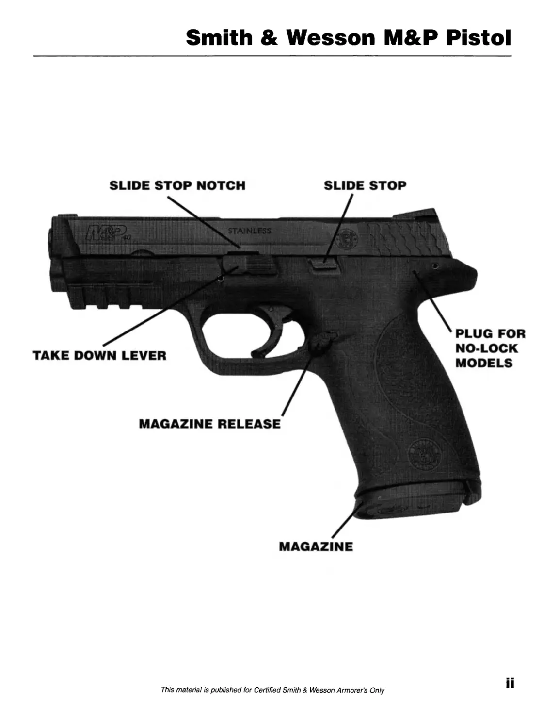
Smith & Wesson M&P Pistol
SLIDE STOP NOTCH SLIDE STOP
MAGAZINE
This material is published for Certified Smith & Wesson Armorer’s Only
THIS PAGE INTENTIONALLY LEFT BLANK
This material is published for Certified Smith & Wesson Armorer's Only
Table of Contents
Section 1 Page
Technical Specifications..............1
This manual contains privileged information.
Section 2_____________________________
Field Strip
A) Clear Firearm....................3
B) Remove Slide...................4
C) Recoil Guide Spring............5
D) Barrel Removal.................5
E) Magazine Disassembly...........6
F) Magazine Reassembly............6
Pistol Field Stripped.............7
Section 3_____________________________
Slide Disassembly
Slide Components....................8
A) Remove Rear Sight..............9
B) Sight Installation.............9
C) Remove Front Sight.............9
D) Sight Installation.............9
E) Remove Striker Assembly........10
Section 4_____________________________
Striker
A) Striker Disassembly..............11
B) Striker Reassembly.............12
Section 5_____________________________
Slide Reassembly
B) Striker Installation............13
Section 8 Page
Frame Reassembly
A) Install Magazine Catch........21
B) Install Trigger Assembly......22-23
C) Sear Housing Block Disassembly.24
D) Sear Housing Block Reassembly...25-26
E) Install Sear Housing Assembly..27
F) Install Slide.................28-29
G) Replacing Grip Insert............30
Section 9___________________________
Safeties
A) Trigger Safety................31
B) Striker Safety...................32
C) Slide Fully in Battery...........33
D) Slide Out of Battery.............33
E) Magazine Safety (Mag. Removed)...33
F) Magazine Safety (Mag. Installed).33
Section 10__________________________
Maintenance.........................34
Section 11__________________________
Lubrication.........................35
Section 12__________________________
Storing Pistols.....................36
Section 13__________________________
Troubleshooting.....................37
Section 6
Extractor Replacement______________
A) Extractor Replacement.........14
B) Check Extractor Hook Location.14
Section 7__________________________
Frame Disassembly
Frame Components...........15-16
A) Remove Trigger Assembly.17-18
B) Remove Sear Housing Assembly..19
C) Remove Magazine Catch......20
iv
This material is published for Certified Smith & Wesson Armorer's Only
THIS PAGE INTENTIONALLY LEFT BLANK
This material is published for Certified Smith & Wesson Armorer's Only
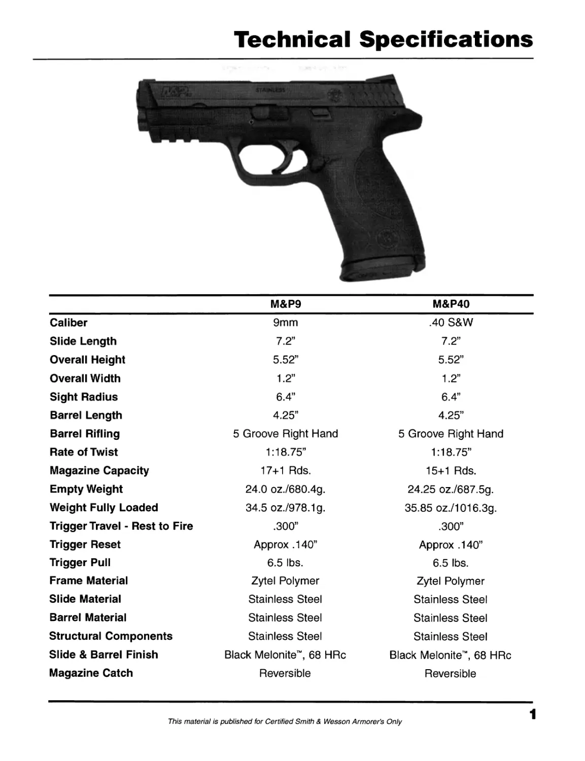
Technical Specifications
M&P9 M&P40
Caliber 9mm .40 S&W
Slide Length 7.2” 7.2”
Overall Height 5.52” 5.52”
Overall Width 1.2” 1.2”
Sight Radius 6.4” 6.4”
Barrel Length 4.25” 4.25”
Barrel Rifling 5 Groove Right Hand 5 Groove Right Hand
Rate of Twist 1:18.75” 1:18.75”
Magazine Capacity 17+1 Rds. 15+1 Rds.
Empty Weight 24.0 oz./680.4g. 24.25 oz./687.5g.
Weight Fully Loaded 34.5 oz./978.1g. 35.85 oz./1016.3g.
Trigger Travel - Rest to Fire .300” .300”
Trigger Reset Approx .140” Approx .140”
Trigger Pull 6.5 lbs. 6.5 lbs.
Frame Material Zytel Polymer Zytel Polymer
Slide Material Stainless Steel Stainless Steel
Barrel Material Stainless Steel Stainless Steel
Structural Components Stainless Steel Stainless Steel
Slide & Barrel Finish Black Melonite™, 68 HRc Black Melonite™, 68 HRc
Magazine Catch Reversible Reversible
1
This material is published for Certified Smith & Wesson Armorer’s Only
THIS PAGE INTENTIONALLY LEFT BLANK
This material is published for Certified Smith & Wesson Armorer's Only
Field Strip
A) Clear Firearm
Keep the firearm pointed in a safe direction
at all times.
1. Remove magazine by depressing
magazine release and removing
magazine downward.
2. Rack slide to rear and lock rearward by
lifting slide stop.
3. Inspect chamber and clear.
3
This material is published for Certified Smith & Wesson Armorer’s Only
Field Strip
В) Remove Slide
1. Push sear deactivation lever down in
frame.
2. Push takedown latch clockwise 90е
3. Hold slide, push down slide stop.
Pull slide slightly rearward then forward
off frame.
4
This material is published for Certified Smith & Wesson Armorer’s Only
Field Strip
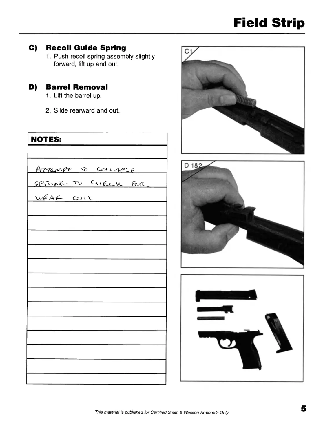
C) Recoil Guide Spring
1. Push recoil spring assembly slightly
forward, lift up and out.
D) Barrel Removal
1. Lift the barrel up.
2. Slide rearward and out.
5
This material is published for Certified Smith & Wesson Armorer's Only
Field Strip
Ensure magazine is unloaded before disassembly!
E) Magazine Disassembly
1. Depress button on bottom of butt plate
and slide butt plate off magazine tube.
2. Remove floor plate, magazine spring,
and follower (Do not remove follower
from spring).
F) Magazine Reassembly
1. Install follower, magazine spring, and
butt catch plate into magazine tube.
2. Install butt plate onto magazine tube
and lock floor plate tab into butt plate.
6
This material is published for Certified Smith & Wesson Armorer's Only
Field Strip
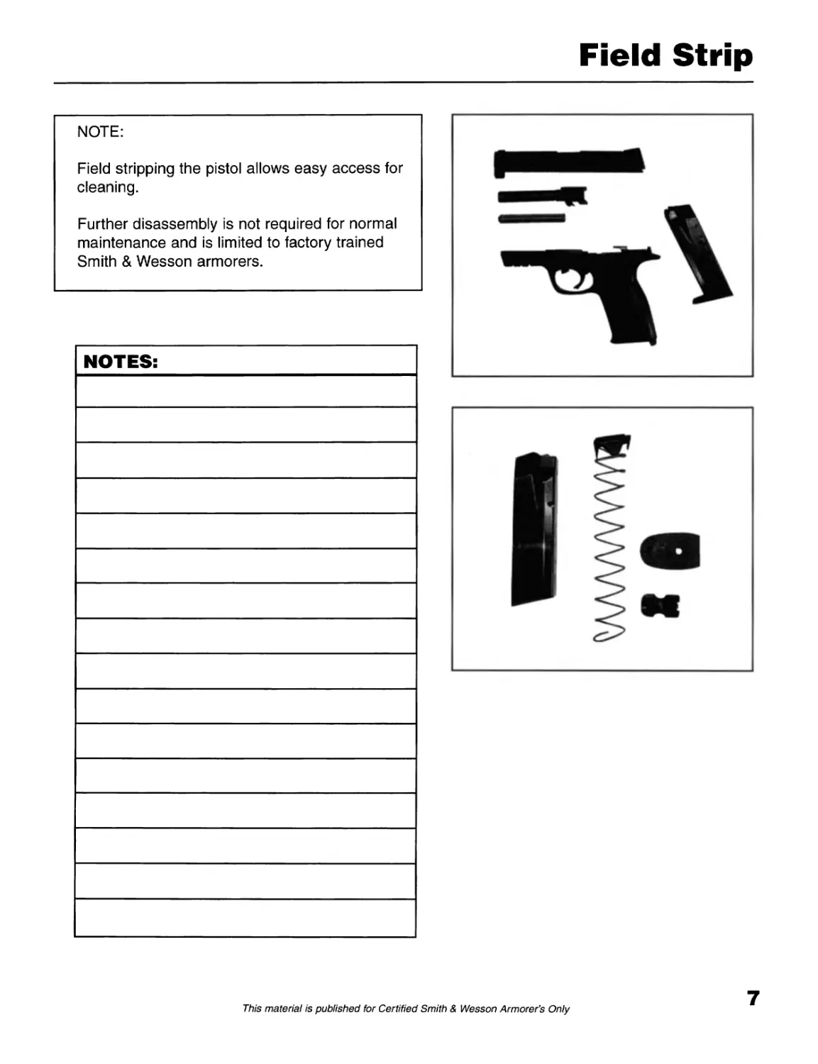
NOTE:
Field stripping the pistol allows easy access for
cleaning.
Further disassembly is not required for normal
maintenance and is limited to factory trained
Smith & Wesson armorers.
7
This material is published for Certified Smith & Wesson Armorer’s Only
Slide Disassembly
SLIDE COMPONENTS
8
This material is published for Certified Smith & Wesson Armorer's Only
Slide Disassembly
A) Remove Rear Sight
1. Loosen alien screw with 1/16”
alien wrench - 2 rotations.
2. Remove sight left to right.
Note: Use your finger to carefully retain the
striker safety plunger, plunger spring and spring
plate. If not, you may lose critical parts.
B) Sight Installation
1. Install striker safety plunger, spring and
spring plate.
2. Install sight right to left.
3. Tighten sight screw.
C) Remove Front Sight
1. Remove sight left to right.
D) Sight Installation
1. Install sight right to left.
Note: Whenever sight is removed or adjusted,
pistol must be test fired to verify accuracy.
9
This material is published for Certified Smith & Wesson Armorer's Only
Slide Disassembly
E) Remove Striker Assembly
1. Using small drift, push down on striker
guide.
2. Remove end cap downward.
3. Push down striker safety plunger.
Remove striker assembly rearward.
10
This material is published for Certified Smith & Wesson Armorer's Only
Striker
A) Striker Disassembly
1. Place striker vertically onto work block
and support at hook.
2. Compress striker spring and remove
striker spring keepers (2).
3. Remove striker spring.
4. Remove striker guide and striker return
spring from striker.
11
This material is published for Certified Smith & Wesson Armorer’s Only
Striker
В) Striker Reassembly
1. Install striker return spring onto striker.
2. Install striker guide onto striker.
3. Install striker spring onto striker.
4. Place striker vertically onto work block
and support at hook.
5. Compress striker spring and install
striker spring keepers (narrow ends
inside spring).
12
This material is published for Certified Smith & Wesson Armorer's Only
Slide Reassembly
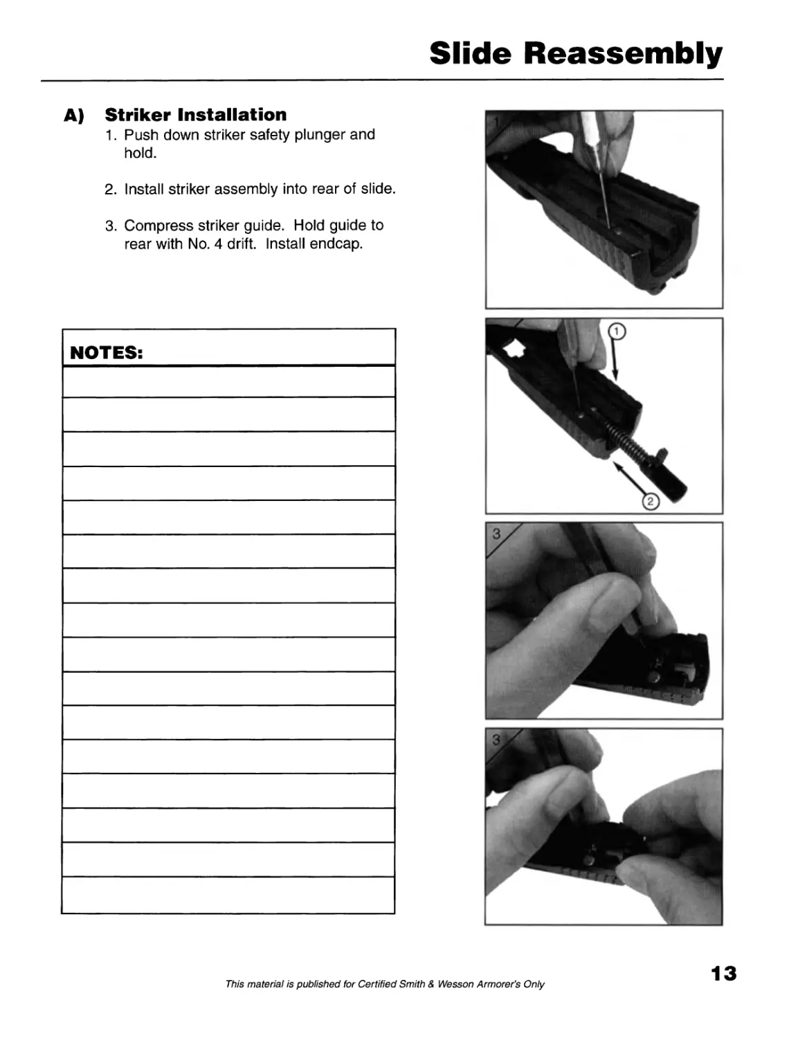
A) Striker Installation
1. Push down striker safety plunger and
hold.
2. Install striker assembly into rear of slide.
3. Compress striker guide. Hold guide to
rear with No. 4 drift. Install endcap.
13
This material is published for Certified Smith & Wesson Armorer's Only
Extractor Replacement
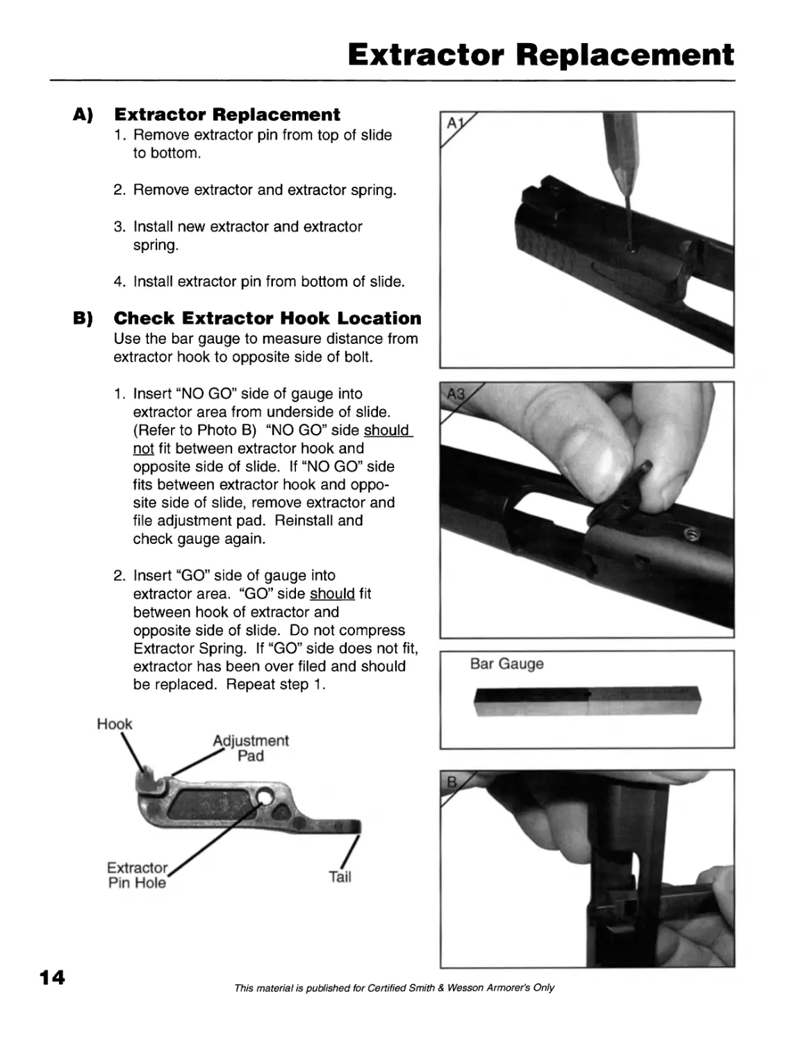
A) Extractor Replacement
1. Remove extractor pin from top of slide
to bottom.
2. Remove extractor and extractor spring.
3. Install new extractor and extractor
spring.
4. Install extractor pin from bottom of slide.
B) Check Extractor Hook Location
Use the bar gauge to measure distance from
extractor hook to opposite side of bolt.
1. Insert “NO GO” side of gauge into
extractor area from underside of slide.
(Refer to Photo B) “NO GO” side should
not fit between extractor hook and
opposite side of slide. If “NO GO” side
fits between extractor hook and oppo-
site side of slide, remove extractor and
file adjustment pad. Reinstall and
check gauge again.
2. Insert “GO” side of gauge into
extractor area. “GO” side should fit
between hook of extractor and
opposite side of slide. Do not compress
Extractor Spring. If “GO” side does not fit,
extractor has been over filed and should
be replaced. Repeat step 1.
Bar Gauge
14
This material is published for Certified Smith & Wesson Armorer’s Only
Frame Disassembly
FRAME COMPONENTS
1 Sight, Front
2 Slide
3 Pin, Extractor
4 F/P Plunger Spacer
5 Spring, Striker Block
6 Striker Block
7 Extractor
8 Spring, Extractor
9 Set Screw, Rear Sight
10 Sight, Rear
11 Guide, Striker Spring
12 Keeper, Striker Spring
13 Spring, Striker
14 Bushing, Striker
15 Spring, Striker Return
16 Striker
17 Barrel
18 Cap, Recoil Guide Rod
19 Spring, Recoil
20 Guide Rod, Recoil
21 End Cap, Slide
22 Plate, Slide End Cap
23 Magazine Tube
24 Follower, Mag. Tube
25 Magazine Spring
26 Butt Plate Catch, Mag.
27 Butt Plate, Mag.
28 Frame
29 Coil Pin, Locking Block
30 Headed Pin, Trigger
31 Grip Strap, Med.
32 Locking Block
33 Takedown Lever
34 Retaining Wire for
Takedown Lever
35 Spring, Trigger Return
36 Pin, Trigger Bar
37 Pin, Trigger Assembly
38 Trigger, Lower
39 Trigger, Upper
40 Trigger Bar
41 Pin, Sear
42 Ejector
43 Sleeve, Lock
44 Spring, Lock
45 Cam, Lock
46 Pin, Sear Deactivation
Lever
47 Sear Housing Block
48 Spring, Sear
49 Plunger, Sear Return
50 Sear
51 Spring, Mag. Safety
Lever
52 Safety Lever, Mag.
53 Deactivation Lever,
Sear
54 Grip Strap, Small
55 Grip Strap, Large
56 Spring, Spacer
57 Plug, Frame Key
60 Assembly, Striker
61 Assembly, Slide
62 Assembly,
Sear Housing Block
63 Assembly, Trigger Bar
64 Assembly, Slide Stop
65 Assembly, End Cap
66 Assembly, Recoil
Guide Rod
67 Assembly, Magazine
68 Assembly, Magazine
Catch
69 Assembly, Frame Tool
15
This material is published for Certified Smith & Wesson Armorer’s Only
Frame Disassembly
16
This material is published for Certified Smith & Wesson Armorer’s Only
Frame Disassembly
A) Remove Trigger Assembly
1. Rotate takedown lever counter-
clockwise until it stops. Lift takedown
lever out of frame.
2. Remove locking block pin in frame, right
to left with 1/8 roll pin punch.
3. Remove trigger pin right to left with
No. 4 drift.
1/8” Roll Pin Punch
17
This material is published for Certified Smith & Wesson Armorer’s Only
Frame Disassembly
NOTE: Be sure not to lose takedown lever
retaining wire (see arrow) when removing locking
block.
A) Remove Trigger Assembly
4. Lift locking block out of frame.
5. Remove slide stop and trigger assembly
from frame.
18
This material is published for Certified Smith & Wesson Armorer’s Only
Frame Disassembly
В) Remove Sear Housing
Assembly
1. Remove sear housing assembly pin,
right to left with 1/8” roll pin punch.
2. Lift sear housing assembly out of
frame with punch.
3. Remove ejector from sear housing
block.
19
This material is published for Certified Smith & Wesson Armorer's Only
Frame Disassembly
NOTE: The magazine catch spring is an integral
part of the frame and is not removable. Be care-
ful not to bend spring excessively.
C) Remove Magazine Catch
1. Move the magazine catch spring from
the magazine catch recess.
2. Slide the magazine catch half-way out
of the frame.
3. Hold magazine release while moving
the magazine catch spring around the
end of the magazine catch.
4. Slide the magazine catch all the way out
of the frame.
NOTES:
20
This material is published for Certified Smith & Wesson Armorer's Only
Frame Reassembly
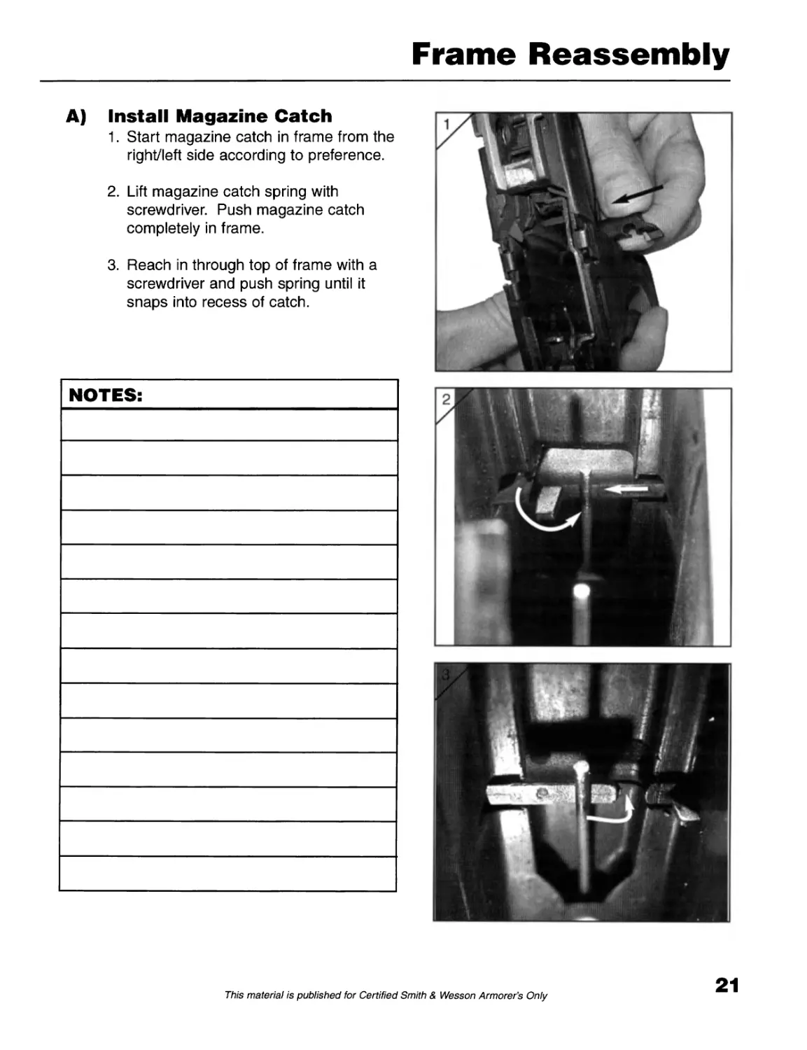
A) Install Magazine Catch
1. Start magazine catch in frame from the
right/left side according to preference.
2. Lift magazine catch spring with
screwdriver. Push magazine catch
completely in frame.
3. Reach in through top of frame with a
screwdriver and push spring until it
snaps into recess of catch.
21
This material is published for Certified Smith & Wesson Armorer's Only
Frame Reassembly
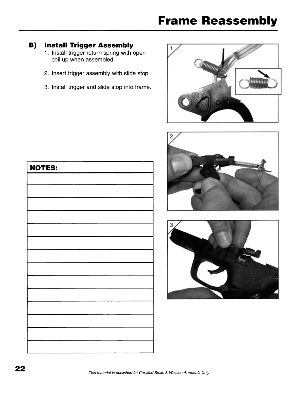
В) Install Trigger Assembly
1. Install trigger return spring with open
coil up when assembled.
2. Insert trigger assembly with slide stop.
3. Install trigger and slide stop into frame.
22
This material is published for Certified Smith & Wesson Armorer's Only
Frame Reassembly
В) Install Trigger Assembly
4. Install takedown lever retaining wire
(see arrow) in locking block
assembly.
5. Install locking block assembly
including takedown lever retaining wire
into frame.
6. Install trigger pin left to right with No. 4
drift.
7. Install locking block pin left to right with
1/8” roll pin punch.
23
This material is published for Certified Smith & Wesson Armorer’s Only
Frame Reassembly
Never Disassemble Sear Housing
Block for Regular Cleaning!!
In the event that disassembly is necessary
because handgun is extremely dirty or has been
submerged, follow these instructions:
C) Sear Housing Block
Disassembly
1. Place finger on top of sear.
2. Push out sear pin with drift.
3. Remove sear, sear plunger and sear
spring.
4. Place finger on levers in sear housing
block.
5. Push out sear deactivation lever pin.
6. Remove sear deactivation lever,
magazine safety lever and magazine
safety lever.
7. Fully disassembled sear housing block.
24
This material is published for Certified Smith & Wesson Armorer's Only
Frame Reassembly
D) Sear Housing Block
Reassembly
1. Insert sear spring and sear plunger into
sear housing block.
2. Place sear on top of plunger and spring.
Compress plunger and spring with sear,
align sear in sear housing block. Install
sear pin (shorter pin).
3. Insert sear deactivation lever into sear
housing block.
(For non-magazine safety models,
skip steps 4 & 5. Go straight to step 6)
4. Place magazine safety lever spring on
magazine safety lever with bent leg of
spring in loop of lever.
25
This material is published for Certified Smith & Wesson Armorer’s Only
Frame Reassembly
5. Insert spring and lever in sear housing
block. Align levers and spring.
Install sear deactivation lever pin
(longer pin).
6. For NON-magazine safety models only:
Insert retaining spring into sear
housing block.
7. For NON-magazine safety models only:
Install the sear deactivation lever pin.
26
This material is published for Certified Smith & Wesson Armorer’s Only
Frame Reassembly
Install Sear Housing Assembly
1. No-Lock Models: Install cap into frame
where internal locking mechanism
would be.
2. Pull trigger to rear with trigger bar out
of frame.
3. Slide sear housing block on tail of
trigger bar.
4. Install sear housing block assembly
into frame halfway, then install ejector
in sear housing block.
5. Push sear housing block assembly
completely in frame.
6. Install sear housing assembly block pin
in frame left to right with 1/8” roll pin
punch.
This material is published for Certified Smith & Wesson Armorer’s Only
Frame Reassembly
F) Install slide
1. Insert takedown lever. Rotate down.
2. Insert barrel.
3. Insert guide rod, small end forward.
4. Ensure that yellow sear deactivation
lever is in the downward position.
28
This material is published for Certified Smith & Wesson Armorer's Only
Frame Reassembly
F) Install slide
5. Align rails of frame with rail grooves
of slide and rack slide rearward.
6. Lock back with slidestop lever.
7. Push takedown lever up. Move slide
forward slowly.
29
This material is published for Certified Smith & Wesson Armorer’s Only
Replacing Grip Insert
G) Replacing Grip Insert
1. Twist frame tool 90е and pull out of
the frame.
2. Lift back strap off rear of frame.
Backstrap can be changed to different
sizes.
3. Repeat in opposite direction for
new grip insert.
30
This material is published for Certified Smith & Wesson Armorer's Only
Safeties
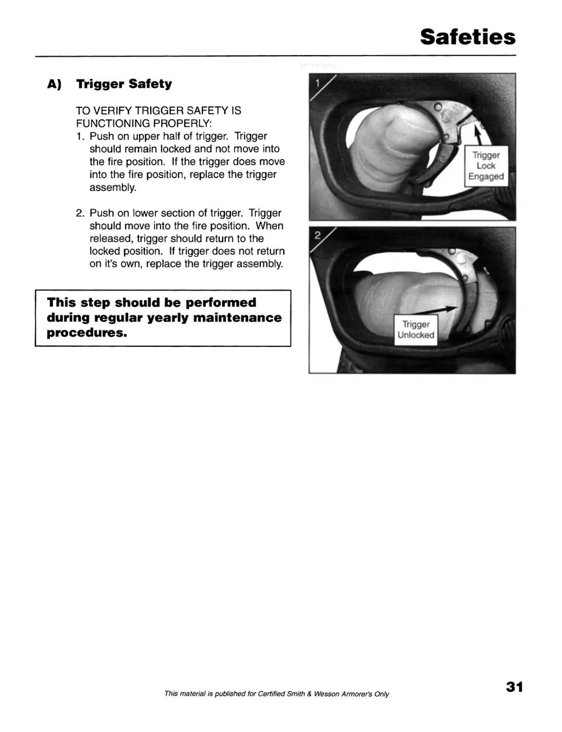
A) Trigger Safety
TO VERIFY TRIGGER SAFETY IS
FUNCTIONING PROPERLY:
1. Push on upper half of trigger. Trigger
should remain locked and not move into
the fire position. If the trigger does move
into the fire position, replace the trigger
assembly.
2. Push on lower section of trigger. Trigger
should move into the fire position. When
released, trigger should return to the
locked position. If trigger does not return
on it’s own, replace the trigger assembly.
This step should be performed
during regular yearly maintenance
procedures.
31
This material is published for Certified Smith & Wesson Armorer's Only
Safeties
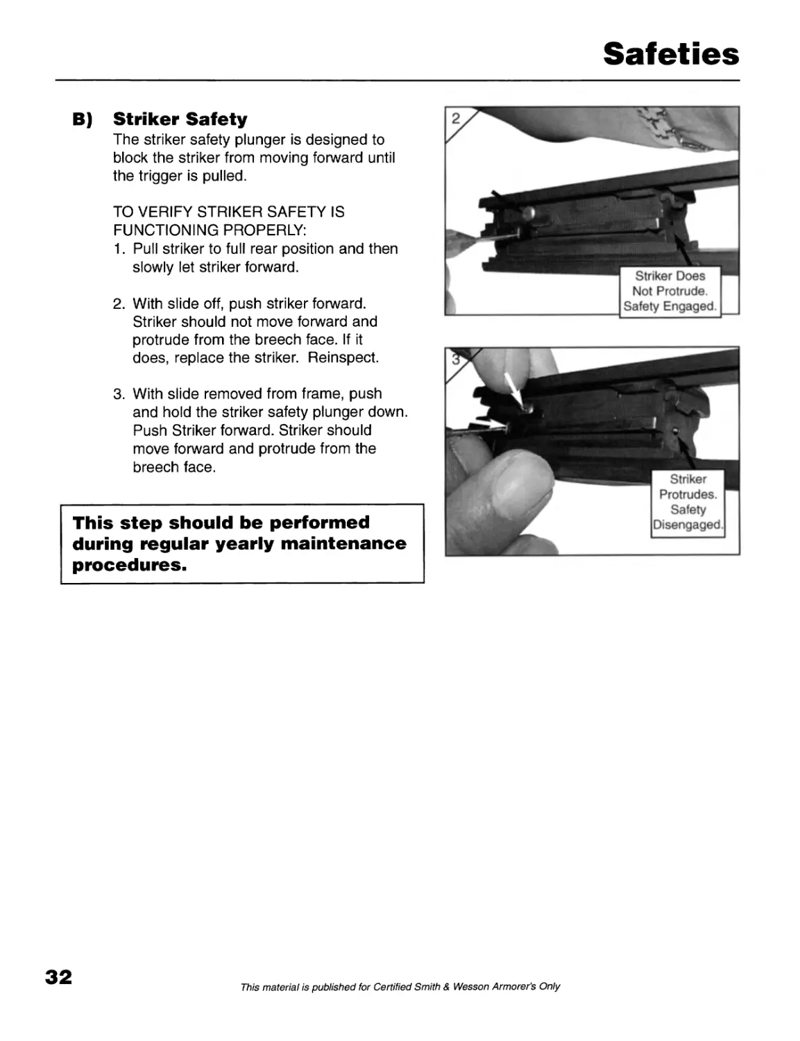
В) Striker Safety
The striker safety plunger is designed to
block the striker from moving forward until
the trigger is pulled.
TO VERIFY STRIKER SAFETY IS
FUNCTIONING PROPERLY:
1. Pull striker to full rear position and then
slowly let striker forward.
2. With slide off, push striker forward.
Striker should not move forward and
protrude from the breech face. If it
does, replace the striker. Reinspect.
3. With slide removed from frame, push
and hold the striker safety plunger down.
Push Striker forward. Striker should
move forward and protrude from the
breech face.
This step should be performed
during regular yearly maintenance
procedures.
32
This material is published for Certified Smith & Wesson Armorer’s Only
Safeties
C) Slide Fully in Battery (Forward)
Firearm will fire when slide is in battery.
Note: Magazine safety version must have
magazine inserted in the frame.
D) Slide Out of Battery
(Not Forward)
Firearm will not fire when slide is out of
battery 1/4” or more (Note space in figure B).
Note: Magazine safety version must have
magazine inserted in the frame.
E) Magazine Safety
(Magazine Removed)
The pistol will not fire.
F) Magazine Safety
(Magazine Installed)
The pistol will fire.
This step should be performed
during regular yearly maintenance
procedures.
33
This material is published for Certified Smith & Wesson Armorer’s Only
Maintenance
The following maintenance program is suggested
to assist the police armorer in planning his own
program depending on frequency of firing, climate,
etc. Note: Use only brass, copper or nylon brush-
es for the following maintenance procedures.
At least every six (6) months or after firing,
a pistol should be cleaned with special attention
given to the following areas:
BARREL
a. Clean with a wire brush using
reciprocating strokes only.
b. The breech face and the locking lug
should be cleaned as well. This can be
best accomplished with a wire type tooth
brush.
c. The feed ramp should be cleaned.
d. When the barrel is cleaned, a lightly
oiled patch should be passed through
the barrel and chamber.
2) SLIDE
a. The slide should be cleaned with a wire
brush with special attention given to the
breech face.
b. The extractor should be cleaned in the
hook area and inspected for freedom
and movement and a damaged hook.
c. Recoil Guide and Spring - wipe with a
lightly oiled patch.
d. Plunger - depress striker safety to
ensure freedom of movement.
5) When the pistol is fully assembled, make
all safety and functioning checks.
6) One (1) drop of oil should be placed in the
following areas - refer to Page 34.
Once a year, the pistol should be completely dis-
assembled by a qualified armorer. (Note: Sear
Housing Assembly Block should never be disas-
sembled for Regular Cleaning)
The frame, slide and all component parts should
be cleaned with a good solvent. “READ THE
LABEL”. Do not use a solvent that could be haz-
ardous to your health or detrimental to the frame
polymer material.
Inspect the parts for wear, unauthorized polishing,
filing, or spring damage.
As the pistol is reassembled, wipe the parts with
a lightly oiled patch. When the pistol is complete-
ly assembled, one (1) drop of oil should be
applied to the following areas - refer to Page 34.
When the pistol is fully assembled, make all of
the safety and functioning checks. Pistol should
be test-fired before returning to service.
NOTE: Carburetor, engine or brake cleaner are
not recommended for cleaning Smith & Wesson
firearms.
3) FRAME
a. Clean the frame with a brush.
b. Wipe out any residue with a cloth.
c. Inspect levers to ensure freedom
of movement.
4) MAGAZINES
a. The magazines should be disassembled
and the parts wiped clean.
b. Reassemble the magazine and check
for freedom of follower.
34
This material is published for Certified Smith & Wesson Armorer's Only
Lubrication
After cleaning the frame, slide and barrel, use a soft cloth and apply a light coating of a premium
grade lubricant to all external metal surfaces and wipe clean.
1) One (1) drop on each rail insert in the frame (4 drops).
2) One (1) drop on the muzzle of the barrel.
3) One (1) drop on the top front corners of the barrel hood.
4) One (1) drop on the tail of the trigger bar.
This will assure proper lubrication of the pistol. Care should be taken not to over-lubricate your
pistol. Excess lubricant can collect large quantities of unburnt powder and carbon residue, which
could interfere with the proper functioning of the pistol.
35
This material is published for Certified Smith & Wesson Armorer’s Only
Storing Pistols
Storing Pistols
Pistols should be stored in a locked, unloaded
condition.
Do not store pistols with a plug in the barrel, other
than the plug that was supplied, as it could contribute
to sweating.
Maintenance or storage rooms should be kept at a
constant temperature with minimum humidity. Guns
should not be stored in any encasement which will
attract or hold moisture, such as leather or vinyl hol-
sters. If pistols are to be stored over a long period of
time, the internal mechanism of the lockwork should
be lightly oiled with an acid-free lubricating oil. The
exterior of the guns, as well as the bore of the barrel
and the chamber, should be lightly coated with an
anti-rust oil. It is an established fact that moisture is
the greatest enemy of metallic objects, particularly in
climates where temperature and humidity are high
and salt air is present.
Extreme care should be exercised that all metallic
surfaces should be kept clean and oiled.
Refer to the Maintenance Section when returning the
weapon to service.
Magazines should be carefully wiped down and very
lightly oiled and inspected before storage.
36
This material is published for Certified Smith & Wesson Armorer’s Only
Troubleshooting
Malfunction Probable Cause Corrective Action
1. Failure to Feed magazine not properly seated into the frame seat (tap) magazine
sticky magazine follower clean and inspect
bent magazine lips replace magazine
underpowered ammunition (light) replace ammunition
weak recoil spring replace
tight extractor replace extractor
2. Failure to Chamber dirty chamber clean and inspect
defective cartridge case replace
weak recoil spring replace
3. Failure to Close dirty slide and barrel inspect and clean
(Lock) dirty chamber mouth clean
weak recoil spring replace
4. Failure to Fire ammunition failure replace
ammunition failure (hard primer) replace
dirt or obstruction in striker channel in slide inspect and clean
broken striker replace striker
5. Failure to Extract overpowered (hot) ammunition replace ammunition
underpowered (light) ammunition replace ammunition
broken extractor replace extractor
dirty chamber clean chamber
shooter induced (limp wrist) evaluate and correct
6. Failure to Eject broken ejector replace ejector
(including Stove underpowered ammunition replace ammunition
Pipes) damaged extractor replace extractor
shooter induced _ dirty pistol evaluate and correct inspect and clean
7. Failure to Stay Open Last Round (Lock damaged magazine damaged magazine follower replace magazine replace
Back) dirty magazine inspect and clean
damaged slide stop assembly replace slide stop assembly
shooter induced (limp wrist) evaluate and correct
underpowered ammunition replace
shooter induced (improper hand placement) evaluate and correct
shooter induced (improper hand placement) evaluate and correct
8. Slide Stop Early improperly installed slide stop assembly reinstall or replace
overpowered ammunition replace
broken slide stop spring replace slide stop assembly
37
This material is published for Certified Smith & Wesson Armorer's Only