/






Text
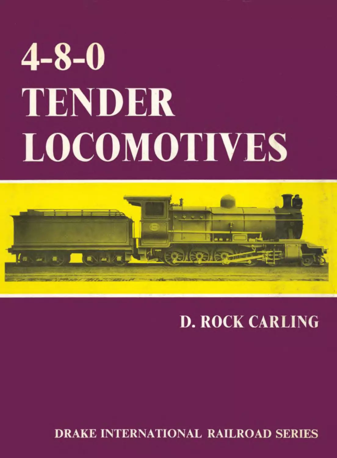
                    4-8-0

TENDER
LOCOMOTIVES

D. ROCK CARLING

DRAKE INTERNATIONAL RAILROAD SERIES

4-8-0 TENDER LOCOMOTIVES
A Chapelon 4-8-0 of the Paris-Orleans Railway (Cliche sncf)
4-8-0 TENDER
LOCOMOTIVES

D. ROCK CARLING

DRAKE PUBLISHERS INC NEW YORK
ISBN 87749 150 X

T ihrary of Congress Catalog Card Number
76-175973

Published in 1972 by

DRAKE PUBLISHERS INC
381 Park Avenue South

New York, New York 10016

© 1972 D. Rock Carling

Printed in Great Britain
CONTENTS

PAGE

Preface	...	...	...	...	...	...	9

Introduction	...	...	...	...	...	...	11

Chapter	1	North America	...	...	...	...	13

Section 1	(a)	On American Railways	...	...	...	13

(b)	Early beginnings ...	...	...	...	13

Section!	Further development	...	...	...	17

Section 3	(a)	The turn of the century	...	...	...	23

(b)	Latecomers	...	...	...	...	25

Section 4 Therestof North America	...	...	...	28

Conclusion	...	...	...	...	...	29

Chapter 2	Europe ...	...	...	...	...	30

Section5	(a)	The background	...	...	...	...	30

(b)	Italy, Ireland and Spanish Industry ...	...	30

(c)	France, the first period	...	...	...	32

Section 6	(a)	Norway, First Spanish Main Line and

Austria-Hungary	...	...	...	34

(b)	Austria, Hungary, and Poland	...	...	37

(c)	Russia ...	...	...	...	...	39

Section?	(a)	Turkey,Portugal,and Sweden	...	...	40

(b)	France, the Chapelon engines	...	...	43

(c)	A Model and some‘Might-have-beens’ ...	44

Section 8 Spain ...	...	...	...	...	47

Conclusion	...	...	...	...	...	53

Chapter 3	Africa ...	...	...	...	...	54

Section 9	(a) Related though separated ...	...	...	54

(b)	The 7th Class ............................... 54

(c)	South Africa	...	...	...	...	57

Section 10	(a) Central Africa	...	...	...	...	59

(b)	West Africa	...	...	...	...	63

(c)	East Africa	...	...	...	...	66

Conclusion	...	...	...	...	...	68
Chapter 4	South America	...	•. •	69
Section 11	(a) The railway scene	•. •	...	69
	(b) Argentina	...	...	69
Section 12	(a) Brazil and Peru ...	. •»	...	74
	(b) Colombia	...	...	76
Conclusion	...	...	...	79
Chapter 5	Australasia			80
Section 13	(a) The Antipodes	...	...	80
	(b) New Zealand	...	...	80
	fcl Tasmania	.. .			81
Section 14	The Australian Mainland ...	...	...	83
Conclusion	...	...	...	86
Chapter 6	Asia			87
Section 15	(a) East of Suez	...	.. .	87
	(b) India ...	...	...	87
	(c) Ceylon and China	• • •	...	91
Conclusion	...	...	...	92
Acknowledgements		...	...	93
Bibliography		...	...	94
Tables				96

Index

110
PREFACE

The 4-8-0 is a type of locomotive that is of quite
respectable antiquity, yet is one of those types of
steam locomotive that is still at work. It has been
used literally ‘from China to Peru’ and from Nor-
way to Argentina and New Zealand; but it was un-
known on the railways of Great Britain, where it
was built only to be sent overseas.

This work docs not purport to be an exhaustive
history of the 4-8-0 type, or to be fully comprehen-
sive : for it to be so would require more extensive
research than either the facilities and information
available to the author or the time and means at his
disposal make practicable.

The subject divides almost naturally into geo-
graphical divisions: North America, Europe, Africa,
South America, Asia, Australia and New Zealand.
North America takes pride of place by virtue of
priority in time, the type having originated in the

United States and having been built and used there
several decades before it was used elsewhere.

There were classes of 4-8-0 that are not recorded
here: statistics indicate that only about four-fifths
of the engines of this type known to have been built
in the USA are included. Because of the differences
in construction a clear distinction is made between
tender and tank engines. The latter are excluded.

Nomenclature has been used as it was at the time
concerned, or at least during most of the period
covered. This seems likely to be less confusing than
the use of names of countries and railways now
current.

The units used in quoting the dimensions of the
locomotives are those at present usual in the United
Kingdom, most of these being equally valid in the
United States and in much of the British Common-
wealth.

INTRODUCTION

The designers and builders of steam locomotives
have always imparted much individuality to their
products and in this respect the 4-8-0 type is no
exception. But there are usually some features com-
mon to a number of designs just as a common object
has been attained by different means in various
countries at various times and on various railways.

If there is one factor that is common to most 4-8-0s
it is that they were mountain- or hill-climbing en-
gines. Another is that most of them were built to
run over light track, often of mediocre quality, and
with sharp curves.

For a locomotive to haul a worthwhile load on a
steeply graded line, it must have plenty of weight
on its coupled wheels, but if the load permissible on
each axle is low, the number of coupled axles must
be increased to obtain the necessary adhesive weight.
Sharp curves make it desirable for the locomotive
to have guiding wheels at its leading end and, if the
track is light or of poor quality, a leading bogie is
preferable to a two-wheeled truck. Moreover, an
engine with a sufficiently large boiler for sustained
uphill work may be too heavy to he properly carried
by only one carrying axle besides the coupled ones.

The 4-8-0 locomotive meets the requirements just
set out in a simple and inexpensive way. In compari-
son with a 2-8-0 its leading bogie enables a larger
boiler to be used for the same axle loads and im-
proves the curving of the engine, but the bogie is
more expensive than most two-wheeled leading
trucks. Compared to a 2-8-2 it has in its favour
that for the same adhesive weight and tractive effort,
it is less liable to slip its wheels when pulling hard,
but the 2-8-2 allows of more freedom in boiler de-
sign, ar some extra cost, and of larger coupled wheels
without affecting the boiler and so of higher speed
if the track will permit.

The conditions mentioned above were met in
the United States during the later decades of the
nineteenth century and that is where and when the
4-8-0 developed after its first tentative beginnings.
There are hills and mountains in plenty and railroad
track was comparatively light. Rails are bought by
the ton, not by the yard: only after traffic had de-

veloped was money available for heavier and better
laid track.

The same may be said of railways in Africa, South
America, Australasia, and Asia in the last decade of
the nineteenth and the first few of the twentieth
century. In Europe railways were well established
before the 4-8-0 was adopted, but many railways
still had light track and in the mountains curvature
was often severe. In the British Isles these condi-
tions were generally lacking, railways were relatively
strongly built and the fairly short distances favoured
the use of more light trains rather than tewer heavy
ones. Only on one Irish railway did conditions occur
that warranted the use of a 4-8-0, though they al-
most did so in two cases in England. But more
4-8-0 locomotives were built in Great Britain than
in any other country and by seventeen locomotive
builders, also more than in any other country, all
for export. This British contribution provides an
element of unity in design of locomotives for a large
number of railways.

A locomotive hauling a load is subjected to weight
transfer. This is because it exerts its pull at rail level,
but the force to haul the train is applied at the level
of the coupling between engine and tender, creating
a turning moment, which can only be resisted by
the transfer of weight from the front to the back of
the engine. For a locomotive with a leading bogie
and no trailing truck the effect is to increase the
adhesive weight and unload the bogie; even if the
leading, or even the first and second, coupled axle
is equalised with the bogie the net effect is still an
increase in adhesive weight. If the engine has a
trailing truck a part of the weight transfer will be to
those carrying wheels and die increase of adhesive
weight will be less. The whole effect is small but is
perceptible and not to be ignored when working near
the limit of adhesion.

A similar effect is due to the track being depressed
under the locomotive, which alters the loading of
the axles, increasing that of those at the ends and
decreasing that of those in the middle; again a loco-
motive with carrying wheels at both ends has its
adhesion reduced more than one with a leading truck
only. Equalised spring rigging reduces this effect,
but docs not eliminate it.

The boiler of a 4-8-0 is of simpler shape than
that of a 2-8-2 or 4-8-2 and this makes for easier
and cheaper boiler making, but, unless the loading
gauge is high and the track permits of a high-pitched
boiler, the firebox of a 4-8-0 boiler may be unduly
shallow if it is wide with its foundation ring above
the wheels, or on bar type frames. The ashpan too
may hr of poor shape, restricting air access to parts
of the grate, especially if ash accumulates on an in-
sufficient slope.

The strength of bridges affects the choice of wheel
arrangement of a railway’s locomotives. It imposes a
limit on total weight, weight per unit length, and
maximum axle load, the nature of each bridge de-
ciding which is the most severe limitation. If the
main restriction is on total weight a 2-8-0 may be
more suitable than a 4-8-0, but if it is on axle load
the reverse will be the case. Where weight per foot
run is the limit the longer engine will be preferable

and some engines have projecting buffer beams and
long tenders for this reason.

Added to the technical factors is one which is im-
ponderable but often decisive, namely the opinions
of the man in authority, which may be based on
experience, prejudice, habit, or even on a single
chance incident.

Even the personalities involved may affect the
issue. The chief civil engineer may be a stronger
personality than the chief mechanical engineer, or
of greater seniority; the general manager may have
his views or the board of directors theirs.

Lastly comes the factor of cost. The most import-
ant aspect of cost may vary from one railway to an-
other and from time to time on the same railway:
it may be possible to spend more on new locomotives
to secure cheaper operation of the line in the future,
or there may be no more money than will buy the
cheapest locomotives that will keep the line going.

The play of these factors is mostly hidden in the
past, though some may be surmised in certain cases.

Centipede as built by Ross W’inans in 1855 (below) and as modified for use on the Baltimore & Ohio
Railroad in 1864 (above). (By courtesy of the Smithsonian Institute. Reproduced from Bulletin 109 of the
Railway and Locomotive Historical Society)
CHAPTER 1

NORTH AMERICA

SECTION 1

(a)	On American Railways

The building and operation of railways in the United
States is typical of the American way of life: it has
always been a matter for private enterprise tempered
by state intervention and regulation. Each railway is
a separate concern run by individuals in an indi-
vidual manner. Rivalry was often intense and was
reflected in the locomotives.

Many railways were pioneer lines in undeveloped
or little developed areas and were built, as such lines
usually are, as economically as possible; the line
could be improved when the traffic warranted the
expenditure. In the early days rails were expensive
and of light weight per yard: the track costs far
more than the rolling stock, many times more than
the locomotives, on most such railways.

The labour originally available for the mainten-
ance and operation of locomotives was rarely highly
skilled, so simple robust construction was essential.

With long lengths of single line and few passing
places operation of freight trains tends to few heavy
trains rather than many light ones, so powerful loco-
motives were needed, but speed was moderate or
low.

The relatively poor track made some sort of lead-
ing truck essential for guidance at any but low speed
and very early the use of a four-wheeled bogie be-
came customary for most locomotives. The simpli-
city of the 4 -‘1 -О made it the preferred type for al-
most all service and only gradually did more coupled
wheels become habitual, first for freight and later
for passenger trains.

Few railways had facilities for the complete de-
sign of locomotives and this work was left to the
locomotive builders. Continuity of design was more
likely to stem from repeat orders from the same
builder than from any other source. Many railways,
having found a manufacturer’s engines to suit them,

obtained most of their requirements from the same
source again and again for many years. Others ob-
tained their engines as opportunity offered, influ-
enced by price or quick delivery; urgent need some-
times meant ordering from two or three builders
simultaneously.

With so much individuality in design the empha-
sis in dealing with North American 4-8-0 locomo-
tives is on the increase in size as time went by and
on changes of design affecting all steam locomotives
such as the increases of boiler pressure.

All this action took place before the backdrop of
a vast continent with great mountain ranges, wide
plains, though the prairie is by no means flat, and
great rivers all in a land that was mainly very sparsely
populated.

The story of the American locomotive is very
largely the story of America and that of the 4-8-0
is a microcosm of the whole.

(b)	Early beginnings

At the very start uncertainty occurs. It has long been
believed that the first 4—8-0 locomotive was the
Centipede, built by Ross Winans in 1855, when it
underwent trials on the Baltimore & Ohio Railroad.
There is a possibility that a locomotive (1) built in
1844 by the Hinkley Locomotive Works for the Bos-
ton & Worcester Railroad may have been a 4-8-0;
if this could be shown to be so it would make the
genesis of the 4-8-0 some eleven years earlier. The
point was noticed forty years ago, but the implica-
tion seems to have been missed (see bibliography).

Reverting to the Centipede (2), for a number of
years the Mount Clare shops of the в л о at Balti-
more were leased to Ross Winans for commercial
locomotive building, the majority of his engines be-
ing sold to the в & o, in particular his well-known
‘Camels’. Friendly relations had existed between
Winans and Samuel Hayes, master of machinery of
the railway, but in 1856 Hayes was succeeded by
Henry Tyson, a man of strong opinions like Winans
himself, but their opinions did not agree and neither
was particularly tactful. An acrimonious dispute en-
sued and Winans refused to sell any more locomo-
tives to the в to.

Construction of Centipede started in 1854 and it
was described, still incomplete, in the Railroad Ad-
vocate of 24 March 1855. Either the paper gave few
details or the description became lost. The engine
was tested between Baltimore and Washington. It
was not until 1863, when Tyson was succeeded by
Thatcher Perkins, that matters improved and then
the в & о was desperately short of locomotives due
to the war between North and South. The в & о was
in the zone of hostilities and had lost many loco-
motives. Winans offered to sell three ‘Camels’ and
Centipede and demanded an answer the same after-
noon! Such was the b&o’s need that he gut agree-
ment to his terms. Centipede entered service early
in 1864 and ran on the в & о for nearly 20 years.

Two reconstructions of this locomotive have been
made, due mainly to J. Snowden Bell, a draughts-
man at Mount Clare under Thatcher Perkins from
1862 and chief draughtsman from 1865. Writing in
1917 Bell stated that no description or drawings of
the locomotive survived and that what little was

known depended on ‘... the recollection, naturally
dimmed by the lapse of years, of those few now
living who, like the writer, have seen the engine’.
After his death two sources of information have
come to light, confirming Bell’s description. The
only appreciable discrepancy lies in the drive to the
feed pump, which was not as shown in the drawing.

The engine had a number of new features. M. N.
Forney, who worked for Winans at the time, stated
that these were due to Thomas Winans, one of Ross’s
two sons, if indeed he did not design the whole en-
gine. The valve gear was remarkable in that two
valves were used for each cylinder, a main valve,
worked by hook (or gab) motion for reversing and
a second cut-off valve, on top of the main valve,
worked by a link motion, to permit expansive use of
the steam. The bogie had no frames: the two axles
were connected to one another by six leaf springs.
The bogie centring device was novel, with a roller
on inclined planes.

Such was the first 4-8-0 tender engine of which
any appreciable record survives; very likely the first
of all. This engine was expected to haul the в & o’s
heaviest passenger trains of the epoch at 20mph up
a gradient of 1 in 451. The dimensions arc set out in
Table I.

The next appearance of the 4-8-0 type was sev-
eral years later, about 1869, and it was the result of
rebuilding a locomotive of another type; the railway
was the Lehigh Valley Railroad, more particularly

Fig 1 The ninth new 4-8-0 built by the Lehigh Valley Railroad; claimed as
the most powerful locomotive in the world in 1880
Fig 2 An 1881 Rhode Island locomotive for the Atlantic & Pacific Railroad,
as in use on the Santa Fe many years later

the Beaver Meadow Division of that line. The Le-
high Valley served the Pennsylvania coal fields and
ran through some mountainous areas. For a line then
concerned mainly in carrying a heavy coal traffic it
was severely graded. The Lehigh Valley was pro-
gressive in locomotive matters and in 1866 it had
acquired rhe first locomotives built as 7-8-fk anH in
1867 the first of the 2-10-0 type. Accounts differ as
to which of these was involved in the rebuilding.
However it may have been, the rebuilding produced
a 4-8-0 (3) that was a success as it was followed a
few years later by newly built engines of the same
type. If it was originally the Ant, one of the 2-lO-Os,
it had cylinders 20in bore by 26in stroke driving 4ft
wheels and the grate area was 28-7sqft.

The next 4-8-Os were built new in the Weatherly,
Pa, workshops of the lvrr, three in 1872 (4) and a
fourth in 1873, to the designs of Philip Hofecker,
master mechanic of rhe Beaver Meadow division.
They had 20in x 26in cylinders and the coupled
wheels of the first three were 4ft lin diameter and
of the fourth 4ft Oin. Another was built in 1878, two
in 1879, and one in 1880, all like the 1873 engine.

Then, also in 1880, there was built at W’eatherly
the famous No20, Champion (5) (Figi) designed
by Henry Hofecker, by then master mechanic of the
Beaver Meadow division, Philip having become
master mechanic of the whole railroad. At the time

this locomotive was claimed to be the most powerful
in the world.

W’eatherly continued to build 4-8-0s at the rate
of from one to five a year until 1888 and both
W’eatherly and South Easton shops rebuilt some, six
in 1891 and two in 1892. Twenty-six were definitely
built at Weatherly and three of those rebuilt at South
Easton did not have their origin recorded, but these
also were probably W’eatherly built. All had 20in x
26in cylinders, except the last two which had 24in
stroke; ten had 4ft 2in coupled wheels and ten 4ft
Oin wheels.

These Lehigh Valley locomotives were the true
ancestors of the breed in the United States and the
4-8-0 type lasted on the lv until 1917.

In 1881 the Rhode Island Locomotive W'orks built
ten 4-8-0s for the Western Division of the Atlantic
& Pacific Railroad. The Western Division of the
A & p ran from Albuquerque, New Mexico, to the
California boundary at Needles: this was in effect
an extension of the Atchison, Topeka & Santa Fe
Railroad. From Needles eastward the line rises over
5,000ft to the first summit at an average of 1 in 130
for 125 miles and further on another 50 miles also
average 1 in 130 to cross the Arizona Divide at
7,310ft above sea level. These locomotives (6) were
Rhode Island's works Nos 993-1002 and originally
bore running numbers 26 to 35, later becoming Nos
Fig 3 The twentieth locomotive and first 4-8-0 built at the Sacramento workshops of the Central
Pacific Railroad, claimed in 1882 as the largest locomotive in the world

237-45 of the AT & SF, one having been scrapped as
a result of a boiler explosion in 1887. The last was
in service on the Santa Fe in 1924, four having been
sold including one to the Belington & Beaver Creek
Railroad and one, Rhode Island’s No 1000 to the
Sacramento State Fair Association. Figure 2 shows
one of them when owned by the Santa Fe. By then
some had migrated further west and were used in
the Tehachapi Mountains of California.

The Santa Fe did not have any other 4-8-Os: the
even steeper gradients elsewhere induced a prefer-
ence for 2-8-0, 2-10-0, and 2-10-2s, the last being
known as the Santa Fe type. But the Santa Fe did
order a 4-8-0 from Schenectady; this was to have
been a ‘Strong’ locomotive with duplex cylindrical
fireboxes (6a). This was in the late 1880s or early
1890s. Failure of other ‘Strong’ locomotives caused
the order to be cancelled.

Another specimen of the type then brought the
4-8-0 into greater prominence. For a trunk line the
Central Pacific Railroad's main line was very severe-
ly graded, crossing the Sierra Nevada mountains at a
height of 7,018ft after climbing from 163ft at Rose-
rille in 87 miles, with a ruling grade of 1 in 45J,
compensated for curvature, which is sharp and con-
tinuous; but there are some pitches at 1 in 37-7.

In 1882 there was built in the railway’s shops at
Sacramento, California, the ‘Enormous’ locomotive
(7) depicted in Fig3. This was Sacramento works
number 20 and the design was due to A. J. Stevens,
the chief master mechanic or locomotive superin-

tendent of the Central Pacific. Again it was the larg-
est and most powerful locomotive in the world. This
was the start of the big power for which this line
has been famous ever since.

So well did this engine perform that twenty-five
more were ordered the same year from the Cooke
Locomotive and Machine Works, of Paterson, New
Jersey. Cooke delivered five of these locomotives (8)
in 1882 and the rest in 1883. They were identical
with the prototype except for cylinders of 7fiin hore
instead of 19in.

These Stevens engines had two peculiar features,
the unusual shape of the firebox and the special
steam distribution, that is to say both valves and
valve gear. The rear end of the firebox was depress-
ed so that the outer shell was below the water level,
leaving no clear steam space. The roof was sloped
down towards the back so that steam bubbles would
flow forward till they reached the upper vertical pan
of the backplate which was in two pieces. The fire-
hole door was in the lower backplate. The firebox
was very lung, 13ft 4 j in io the tubeplate, the grate
being 9ft in length. It is not clear what object Stev-
ens had in mind in using this abnormal construction,
which must have been costly to build and maintain:
it did give more room in the cab.

The special valve gear operated four slide valves
for each cylinder, two, one for each end, being
worked by Stephenson valve gear, but used for re-
versing only, and two more, on top of the first two,
for controlling the cut-off, these being operated by
a third eccentric through a rocking lever with a slid-
ing block on one arm. The use of a double valve
gear is reminiscent of Centipede, but separate valves
for each end of the cylinder were novel on a loco-
motive. This valve gear gave very good steam dis-
tribution even at short cut-offs; short as understood
for a saturated-steam engine with a boiler pressure
low by modern standards. At long cut-off and a
speed of 8mph the indicated mean effective pressure
was 1241b/sqin, which is over 91 per cent of the
boiler pressure of 1351b/sqin, that is to say more
than the 85 per cent normally used to calculate the
tractive effort at starting.

In their original condition these engines hauled
trains of 395 tons up the long 116ft per mile grades
with some lengths of 140ft per mile, at a mean speed
of 8mph. [Unless otherwise stated 'ton' means 2,240
lb; a short or US ton=2,0001b and a metric ton, or
tonne = 2,204-6lb.) One of them, the Mastodon, was
shown at the Exposition of Railroad Appliances in

Chicago in 1883. It was from this engine that the
correct generic name of the 4-8-0 type is derived,
though the less definite Twelve Wheeler may also
be used. Though of long standing, the use of the
word ‘Mastodon’ to described the 4-10-0 type is
not correct.

It was probably the continued good work of this
class on the heavy grades and sharp curves of the
Sierra Nevada line that caused the 4-8-0 type to be
more widely accepted and to be built by several
other firms of locomotive builders. In course of time
all these engines received new boilers with higher
steam pressure, increasing their weights by various
differing amounts and they were otherwise modified
also, but it is of note that the prototype lasted until
it was scrapped in 1935 and two of the Cooke en-
gines were scrapped in 1949 and two more in 1950.

It will now be more convenient to follow the de-
velopment of the 4-8-0 on each railway in turn
rather than sticking to chronological order.

SECTION 2

FURTHER DEVELOPMENT

In 1885 the Central Pacific had become a part of the
Southern Pacific Railroad and so it is no surprise to
find that railway ordering more 4-8-0 locomotives
in 1889. These ten engines were built by the Schen-
ectady Locomotive Works, of Schenectady, NY, and
they were little larger than the Stevens engines; they

did not have the special features of those locomo-
tives, but the boiler pressure had gone up to 1601b/
sq in, which would permit more economical use of
the steam in the cylinders (11).

Two years later the Southern Pacific took delivery
of the first of a class of two cylinder Cross com-

Fig 4 Outline of an 1895 Schenectady locomotive for the Southern Pacific Railroad

17
Fig 5 One of the Great Northern Railway’s class Gl, built by Brooks in 1891

pound 4-8-0 engines from Schenectady, works No
3547, a dozen more, works Nos 3760-71, following
in 1892. These locomotives (12) were, the author
believes, the first compound 4-8-0s and compound-
ing, on various systems, enjoyed quite a vogue in
the USA for the next decade or so. They had 20in
diameter high-pressure and 29in diameter low-pres-
sure cylinders, both with 26in stroke, 1801b/sqin
boiler pressure and 4ft 3in diameter coupled wheels.
Eight more followed, still in 1892, but with 30in
diameter low-pressure cylinders; the Schenectady
works numbers followed on immediately after those
of the last batch. They were nearly as long-lived as
the Stevens class, various dates of scrapping having
occurred as late as 1952 and even one in 1954. They
had been rebuilt as two-cylinder simples with 20in
x26in cylinders and 1701b/sqin steam pressure.

The Southern Pacific’s ever growing traffic over
the Sierra Nevada gradients called for more locomo-
tives in 1894, when fourteen heavier 4-8-0s were
ordered from Schenectady. These locomotives (19)
(Fig 4) were delivered in 1895 and were much larger
than either the Stevens engines or any of the previ-
ous batches from Schenectady; in a dozen years the
engine weight had gone up from 55 to 78 tons and
adhesive weight from 47-3 to 65-6 tons, the nominal
tractive effort had risen from 23,200 to 35,1001b;
simple expansion had been reverted to. They were
set to haul trains little heavier than those taken by
their predecessors, about 406 tons, but the average
speed up the grade had increased from 8 to 12mph,
or by 50 per cent. As well as on the Sierra Nevada

line these engines worked in Southern California
where the Southern Pacific climbs through the Te-
hachapi mountains. Several lasted until 1950 and
one till 1951 after being rebuilt in 1905.

In 1898 Schenectady was again building 4-8-0s
for the Southern Pacific, which had reverted to com-
pounding. There were ten of these two-cylinder en-
gines (26) with cylinders of 23in and 35in bore by
32in stroke. Like the earlier compounds they were
rebuilt as simples between 1911 and 1917 and lasted
until various dates between 1949 and 1953, except
the first, Southern Pacific No 2914, Schenectady
works No 4807, which ran until 1955 and is pre-
served at Bakersfield, California, a partial atonement
on the part of the Southern Pacific Railroad for the
scrapping in 1935 of the historic No 229 of the
Central Pacific. The Southern Pacific sold some of
its 4-8-0s to various minor railways, but a number
also were transferred, as will be described later, to
its subsidiary south of the border. When in Cali-
fornia and Oregon in 1927 the author saw some of
these old 4-8-0 Southern Pacific engines, but was
uut able lu identify the baldies iu which any of
them originally belonged.

Going back now, it was in 1887 that the Baldwin
Locomotive Works of Philadelphia built some 4-8-0
locomotives for the Pennsylvania & New York Rail-
road, which was, or became, the northern division
of the Lehigh Valley RR. More of these engines (9)
were built in 1891, by which time there were twenty-
five of them, the last ten having somewhat larger
boilers.
Also in 1887 Schenectady built three 4-8-Os (10)
for the Beech Creek Railroad. More followed at in-
tervals of one or two years till there were thirteen
by 1891; they were followed in 1893 by eleven more
(18) with driving wheels 6in larger and three more
in 1897 (25). Finally another five followed in 1898
with wheels 3in smaller. The Beech Creek was situ-
ated in the upper valley of the Susquehanna river
and gave access to coalfields owned by the New York
Central. It was a Vanderbilt road and became part
of the New York Central System, all these 4-8-Os
passing to the nycrr. The main line of the nyc is
known as ‘The water level route’, but there are
plenty of hills and mountains on either side.

In 1891 Schenectady built two small 4-8-Os for
the Fremont, Elkhorn & Missouri Valley RR, one
of the then many narrow gauge railways in the USA,

being of 3ft Oin gauge. They were oil burners at one
time and also at some period burned coal (13). An-
other followed in 1892 and in 1902, after the railway
had become a part of the Chicago & North Western
Railway, two more (41) came from the American
Locomotive Company’s Schenectady works. It was
not unusual for some American railways to change
from oil to coal burning and vice versa as the prices
of coal and oil varied.

Also in 1891 Brooks built fifteen 4-8-Os for the
Great Northern Railway, which were quite an ad-
vance on earlier locomotives of the type. A single
further one followed in 1893 for the ^Montana Cen-
tral Railroad, which became part of the GN; the GN
later classified them Gl. One of them was Brooks’
works No 2000 (14) (Fig 5).

The next American 4-8-Os were appreciably

Fig 6 Schenectady’s 4-8-0 locomotives for the Duluth and Iron Range Railway (above) and for the
World Columbian Exhibition of 1893 (below)
larger than any, other than the GIs, previously built
and a rivalry developed between Schenectady and
the Brooks Locomotive Works of Dunkirk, NY, these
two builders taking up all the spaces in Table II
except one. It may be that other firms built 4-8-0s
during the next half-dozen years, but only one class
built by Baldwin has been located by the author.

Brooks built one or more engines (15) for the
Iron Range & Huron Bay Railway in 1892, a little
larger than the gn 4-8-0 of 1891, but very like it.
Next year Schenectady built ten a little larger for
the Duluth & Iron Range Railway (16) (Fig 6).
These two railways were concerned mainly in the
transport of iron orc from the immense deposits in
the Mesabi, Vermillion, and Iron ranges to the head
of Lake Superior for shipment to the iron and steel
industry of the USA. The d&ir has become the
Duluth, Missabe & Iron Range Railway, but the
author has not discovered what has become of the
ir & HB. The I) & IR climbed rapidly from about 700ft
to about 1,650ft in just over fourteen miles, averag-
ing 1 in 80, but the first three miles are at about 1
in 45, a formidable grade even for trains of empty
ore wagons; gradients against the loaded trains are
less severe but include some four miles averaging
1 in 110.

The d&ir received four more 4-8-0s from
Schenectady in 1895 and ten, some in 1896 and
some in 1899 (22) (Fig 10) from Baldwin, a little
heavier than the 1893 engines.

In 1893 there took place the World Columbian
Exhibition in Chicago and both Brooks and Schen-
ertady exhibited locomotives. Amongst these were

two 4-8-0s, one by each firm. That by Brooks was
for the Great Northern (14) (Fig 5). Schenectady’s
4-8-0 exhibit (17) (Fig 6) closely resembled that for
the D & ir; was it also for that line or for another?

Brooks built a single 4-8-0 (20) for the St Law-
rence & Adirondack RR in May 1896. This bore
the name Manitou with the running number 15;
Brooks’ works number was 2667. This railway was
a consolidation in that year of an earlier line of the
same name, which was located in the Province of
Quebec just north of New York State, with the Mo-
hawk & Malone, Malone & St Lawrence, and the
Canadian Southwestern. By lease of a branch of the
Grand Trunk and running powers over the Canadian
Pacific this provided a through route to Montreal.
The name suggests penetration into the Adirondack
mountains and implies climbing. Whether the 4-8-0
worked in the USA, in Canada, or in both, the
author cannot say. In the following year the whole
group of lines was leased by the New York Central,
which had been behind the whole project. This
4-8-0 was sold in November of rhe same year to rhe
Buffalo, Rochester & Pittsburgh RR, of which more
later.

Meanwhile, still in 1896, Schenectady had built
four two-cylinder compound 4-8-Os (21) (Fig 7) to
the requirements of E. M. Herr, superintendent of
motive power of the Northern Pacific RR. This is a
transcontinental line and has to cross the vast moun-
tain barrier commonly thought of as the ‘Rockies’,
but consisting of several ranges. These locomotives
had cylinders 23in and 34in bore by 30in stroke and
were intended for hanking freight trains up seven-

Fig 7 A two-cylinder compound of 1896 for the Northern Pacific Railroad

20
Fig 8 One of class G5 of the Great Northern Railway built by Brooks in 1897
and claimed as the heaviest locomotive in the world

teen miles of 1 in 451 on the line between Helena,
Montana, and Missoula, Montana. On test one of
them developed 1,230 indicated horsepower at 112
rpm equal to 18-3mph, a very creditable figure at
that date: they had been designed to attain l,200ihp
for three hours continuously. They had one con-
structional feature of some interest: so large was the
low-pressure cylinder that there was no room for
the usual flange for bolting the casting to the frame;
instead the bolt holes were drilled through into the
bore of the cylinder and counter-bored to take the
bolt heads, these being covered with Babbitt metal
and smoothed off. This was possible in the low-
pressure cylinder of a saturated compound without
fear of melting the Babbitt metal. These were the
first 4-8-Os to weigh over 80 tons without tender.

In December of 1896 the Buffalo, Rochester &
Pittsburgh RR placed in service the 4-8-0 it had
bought secondhand, giving it the number 139 and
name Mastodon. It was more appreciated than by
its previous owners as it worked on the br & p till
1918 and three more were ordered from Brooks in
1897 (23), works Nos 2780-2 and br & p Nos 140-2.
The original engine was eventually sold to the Cum-
berland & Manchester Railroad.

During 1898 Brooks supplied nineteen more
4-8-0s (27) to the br & p rather smaller than the
earlier engines. They had 20in x 26in cylinders, 4ft
7in wheels and a total engine weight of 70-55 tons.
Fifteen more followed in 1899. Originally the br & p
used its 4-8-0s for helper service on gradients rarely
as steep as 1 in 90, but they enabled the heavy coal
trains to maintain uphill the same average speed
that the single smaller train engine could achieve on
the level. The br & p grades were severe for a line
carrying a heavy mineral traffic. More 4-8-Os, to be
mentioned in the next section, came to the br & p
later.

The Butte, Anaconda & Pacific is a short railway
in western Montana, not far from the main lines of
the Northern Pacific, with a heavy mineral traffic.
In 1897 Schenectady built three 4—8-0s (23a) for
this line, which were sold in 1917 to the Nashville,
Chattanooga & St Louis Railway, after electrifica-
tion of the вл & p’s main line.

In December 1897 Brooks turned out the first
two engines of the Great Northern Railway’s class
G5 (24) (Fig 8), built to the requirements of J. O.
Pattee, the superintendent of motive power of the
gn, for ‘Heavy mountain and pusher service’ on 1 in
45 grades. The Great Northern and the Northern
Pacific were bitter rivals at this time and no doubt
Pattee was keen to have a more powerful locomotive
than Herr’s big compound. Five more G5s followed
in 1898 and one was Brooks’ 3,000th locomotive.
They were claimed once again to be the heaviest
locomotives in the world, as they weighed 95 tons
without tender, but this distinction was held for
only a few months.

The Great Northern obtained another class of
4-8-0 in 1898, also from Brooks, which was for road
service, being larger than the G1 but considerably
smaller than the G5, with 19in x 32in cylinders and
the same boiler pressure and wheel diameter; this
G2 (28'1 followed in 1900 by the G4 class (37),
also from Brooks, which had a slightly larger boiler.
Additionally in between the GN obtained some
4-8-Os, later classified G3, from the Rogers Loco-
motive Works of Paterson, New Jersey (34). All
these engines originally had 2101b/sq in steam pres-
sure, but this was later reduced to 1801b/sqin, per-
haps due to liability to slipping or to difficulties in
boiler maintenance. Some G3s were later super-
heated and became oil burners (35).

It is now opportune to make a digression about
some technical features of the engines and to take
stock. One point concerns the position of the driving
axle. The drive could be taken on either the second
or the third coupled axle, giving rather short or long
connecting rods, respectively. A short connecting
rod is lighter, but the angularity at mid-stroke is in-
creased : a larger angle means higher thrusts on the
«lidi* hare wirh grpatpr tpnHpncy гл makp rhp pnginp
pitch and roll. A heavy connecting rod adds to the
difficulty of balancing the reciprocating and rotating
masses correctly and so increases the dynamic aug-
ment on the track: this is not important if speeds
are low. Incidentally, balancing of American loco-
motives was for many years much less sophisticated
than it was in Europe. The Baldwin, Brooks and
Schenectady engines had the drive on the second
coupled axle, but Centipede and the Central Pacific
ones drove on the third.

Another point concerns the position of the wheels
with the blind, flangeless, tyres; all these and most
subsequent American 4-8-0 type locomotives had
at least one of the coupled axles so fitted and often
two. Winans put the blind tyres on the driving and
intermediate axles, which was also Schenectady’s
normal practice; Brooks usually put them on the
leading and intermediate axles. No doubt the re-
quirements of the railway sometimes overruled the
builder’s custom. The Lehigh Valley engines of

1880 had only the second coupled axle with flange-
less wheels and the Central Pacific engines had no
flanges on the leading and driving wheels. Some of
the later Brooks engines had only the leading coupled
wheels with blind tyres.

A third point is one that recurs and that affected
all locomotives, namely the raising of the boiler to a
higher level. In early days it was thought essential
to keep down the centre of gravity of the locomotive
so boilers were placed as low as practicable, but as
they became larger it also became necessary to place
them higher above the level of the rails. The process
took place partly as a gradual increase and partly as
sudden jumps in the height above rail of the centre
line of the boiler barrel. Ver rhe 4—%-G type locomo-
tives this dimension was about 6ft lin in 1880 and
6ft 6in in 1882, but had increased to 8ft 2Jin by
1893 and, exceptionally, to 9ft 5in by 1897. Not
only had the boilers become larger but the fireboxes
were being placed above instead of between the bar
frames; the next move would come with the need
for still larger grates above the wheels, but that was
not yet. With a wide grate extending out sideways
there must be enough room above the wheels for a
reasonable depth of ashpan; if the slope of the ash-
pan is too flat the ash will not shake down and will
soon restrict the flow of air to the sides of the grate.
This is less important for an engine making only
short runs if there is time between runs for the side
slopes of the ashpan to be cleared. W’ith oil firing,
there need be no true ashpan and the problem is
cased, but adequate firebox volume is essential.

Ti iq я1ол nf	tn note how the number of

4-8-Os had grown, though no exact tally can be
given. After a shaky start with perhaps one on the
в & w and one definitely on the в & о came a total
of 55 on the Lehigh Valley; then 10 on the A4P
and 26 on the Central Pacific. Were any built in the
interval from 1883 to 1887 exclusive? The Beech
Creek had had 32 and the Southern Pacific had re-
ceived 58 besides those from the Central Pacific. The
fe & MV had had 3 to date with 2 more to come:
the GN had had 43 also with more to come. The
author’s information includes no indication of the
number of locomotives supplied to the Iron Range
& Huron Bay; as this was a line with heavy orc
traffic an estimate of about fifteen seems not un-
reasonable. The hr & I* had so far received 23, the
Northern Pacific had 4, that have been noted, the
ba & p 3 and the d & ir about 19 with more to come.
This brings the total to at least 278 and perhaps
some twenty more, mentioned above, besides any
that have not come to the author’s notice.
SECTION 3

(a)	The Turn of the Century

As the nineteenth century drew towards its close
several other railways began to use 4-8-0s and some
of those already noted obtained more of them.

The Chicago & Eastern Illinois RR had some
4-8-0s of a new kind: the author has tentatively
dated these engines in 1899, but again the true date
might be a little earlier or later. They were two-
cylinder compounds and were heavier than any pre-
vious 4-8-0s other than the GN’s G5. The builder of
these locomotives (29) is not stated in the author’s
data, but Schenectady is likely. The firebox was of
the Wootten pattern with a very large grate intended
for burning small coal, usually anthracite, which
made the firebox almost as wide as the locomotive,
but, being above the wheels, also relatively shallow.
When these fireboxes first came into use small an-
thracite was virtually a waste product and was very
cheap. Because of the width of the firebox the cab
was placed in front of it astride the boiler barrel.
This gave the driver a better view ahead, but was
awkward in several respects. W’hen firing, the fire-
man had only a rudimentary shelter to protect him
and had to climb up to a precarious footplate well
up on the firebox side to reach the main ’Mother
Hubbard’ cab. These cabs had a considerable vogue
in America for a time.

The Central Railroad of New Jersey also had
4-8-Os with Mother Hubbard cabs and modified

Wootten fireboxes (30). All came from Brooks, fif-
teen and ten in 1899, fifteen in 1900, and eleven in
1901. The first built in 1901 was shown at the Pan-
American Exposition in Buffalo. As built the first
batch weighed nearly 90 tons each and had 21 in
bore cylinders, which were snnn lined up to 20in;
the later engines were so built. After one or two re-
buildings, mostly between 1917 and 1925, which
increased their weight by seven and ten and a half
tons, they were withdrawn between late 1934 and
late 1948. They were for drag freight.

One of the main routes of the crnj, or Jersey
Central, lies mainly in Pennsylvania, penetrating the
anthracite region, and is severely graded. From
Allentown the line climbs with increasing gradients
for sixty miles from under 250 to about 1,600ft; the
subsequent drop to Wilkes Barre is more abrupt, to
under 550ft in about fifteen miles including 800ft
in some six miles, about 1 in 40.

For the Delaware, Lackawanna & Western RR,
another line serving the Pennsylvania anthracite
region, fifteen 4-8-0s (31) (Fig9) with Wootten
fireboxes and Mother Hubbard cabs were built by
Brooks also in 1899. They were to the requirements
of J. W. FitzGibbon, superintendent of motive pow-
er and machinery, and weighed over 90 tons each.
Again the cylinders were bushed to reduce the dia-
meter from 21 in to 20in almost immediately and

Fig 9 A ‘Mother Hubbard' for the Delaware, Lackawana & Western Railroad built by Brooks in 1899;
those for the Central Railroad of New Jersey were very similar
Fig 10 The Illinois Central Railroad’s only 4-8-0 of 1899, claimed as the heaviest and most powerful
locomotive in the world. (Courtesy Illinois Central Railroad)

later die boilei pressure was reduced from 200 to
1851b/sqin. They were Brooks works Nos 3304-18.

Still in 1899 Brooks produced yet another ‘heav-
iest and most powerful locomotive yet built’. This
engine (32) (Fig 10) was for the Illinois Central RR,
which had a heavy coal traffic as well as much gener-
al freight like most railways radiating from Chicago,
and was a normal Brooks product except for its large
size. It held its distinction into 1900 and, as far as
4-8-Os are concerned, until 1910. It was sold to the
Peoria & Pekin Union RR in 1917. It hauled trains
of 1.825 tons up 38ft/mile. 1 in 139, with curves of
3°, 1,909ft radius, at 15mph.

So much for Brooks’ new customers for 4-8-Os
in 1899, but their old customers for the type were
also in the market. In that year they built a further
fifteen for the br&p identical with those of 1898.
Baldwin completed delivery of the ten 4-8-Os to
the D & ir.

Meanwhile Schenectady too had found a new
customer for 4-8-Os, the Boston & Albany RR to
which they supplied five two-cylinder compounds
in 1899 (33) and six more in 1900. The в & A was
leased by the New York Central, which left ir largely
as a separate operating unit, but the locomotives
were renumbered in the New York Central’s series
as 2632-42. The в & a crossed the mountains of New
England and could not avoid heavy grades.

The last 4-8-Os to be noted for 1899 were fifty
built by Rogers for the gn as mentioned already
(34). Delivery continued into 1900.

It is worth mentioning the further upward trend
of the boilers of these 4-8-Os, the height of the

centre line being 9ft 2in for the c & El, 9ft 3in for
the dl & w, and 9ft 8in for the Illinois Central ones.
Ideas were changing and the track was being better
maintained. Other things being equal an engine with
a high centre of gravity will roll more than one with
a low one, but will exert lower transverse forces
when the line of the track is irregular or when en-
tering curves; it needs the track to be well main-
tained as regards cross levels. If speed on a curve is
excessive the engine with the high centre of gravity
will tend to overturn before derailing, but that with
the low one may derail before overturning.

The year 1900 saw the last delivery of locomo-
tives of the 4-8-0 type to the GN, ten of class G4
(37) coming from Brooks. Twenty 4-8-Os were still
in service on the gn in 1950. A final six 4-8-Os also
were built by Schenectady for the D & ir, about three
and a half tons heavier than those of 1893.

The dl & w had five more 4-8-Os (36) in 1900,
built by the Dickson Locomotive Works of Scran-
ton, Pennsylvania, an important town on the Lacka-
wanna. They differed from the Brooks engines of
1899 only in the use of flat slide valves instead of
piston valves. These also had their boiler pressure
reduced, this time to 1701b/sqin, but the cylinders
were not reduced in diameter. The Lackawanna used
its 4-8-Os mainly in pusher service: there are some
steep gradients crossing the Pocono mountains.
Some of the Brooks engines were later given 21 in
diameter cylinders with slide valves. All twenty
4-8-Os had been scrapped by 1923.

The br & P had another class of 4-8-Os (38) from
Brooks in 1900 and 1901, eleven in the former and
six in the latter. They were the br & P’s last 4-8-Os
and were larger than the previous scries, but not so
heavy as the original four engines of 1896 and 1897.
Some 4-8-Os lasted on the br & p until 1923, but
most were sold during the previous five years. The
br & p 4-8-Os spread to various minor railways,
lumber companies, and industrial concerns from the
Atlantic to the Pacific coasts and as far south as
Texas in the USA, also to Mexico and to Cuba. The
majority were disposed of to the Southern Iron &
Equipment Company, an American equivalent of
‘Boulton’s Siding' in England. It has been possible
to trace the disposal of almost every one of these lo-
comotives. A couple of dozen were rebuilt as 2-8-0s.
Some passed through st & e’s hands more than once
and as late as 1936 and 1937.

Schenectady built a large 4-8-0 in 1901 for the
Butte, Anaconda & Pacific (39) (Fig 11), larger than
the G5, but not as heavy as ic No 640. It was a
two-cylinder compound with 23in and 34in bore by
32in stroke cylinders driving 4ft 8in wheels and the
steam pressure was 2101b/sqln. Another followed
from Alco in 1903 and two more in each of the years
1905 and 1906. These were probably the last two-
cylinder compound 4-8-Os built in and for the USA.

In 1901 there was a large amalgamation of a num-
ber of American locomotive building firms to form
the American Locomotive Company, the two major
components being Schenectady and Brooks, but it
also included Hinkley, Cooke, Rhode Island, Dick-
son, and Rogers, this last not till 1905, and others
as well.

It was typical products of the Brooks works, if
nominally ‘Alco’ built, that formed a class of fifteen
4-8-0 locomotives (40) delivered in 1901 to the St
Louis, Iron Mountain & Southern Railway. Six of

them were oil burners and nine coal. Two more
followed in 1903.

In 1917 the stLiM&s amalgamated with the
Missouri Pacific, which in 1950 still owned seven
4-8-Os, which had been rebuilt, superheated, at
some time. The last was scrapped in 1953.

From this time onwards the popularity of the
4-8-0 in the United States began to wane because
further improvement of the track allowed higher
axle loads, so that the simpler and cheaper 2-8-0
could do all that the 4-8-0 could at low speed and
the 2-8-2, with larger coupled wheels clear of the
firebox, was better suited on reasonably good track
for the higher speeds being demanded of some trains.

Statistics for 31 December 1904 give 557 4-8-Os
on the railways of the USA, 493 simples and 64
two-cylinder compounds. To put these figures in
perspective, there then was a total of 46,116 steam
locomotives, 11,399 2-8-Os, 11,323 4 4 Os and
9,232 4-6-Os.

Of these 4-8-Os those noted above total at least a
further 198 and possibly abour 205 to add to the
1898 totals or say 461 at least and perhaps about
500. There arc quite a few missing! For the com-
pounds the score is similar, 42 definitely and prob-
ably about 56 out of 64.

(b)	Late Comers

After the general decline of the 4-8-0 in the US
there were two large deliveries of such locomotives,
both from Baldwin and both to the Norfolk & West-
ern RR. The N & W was a coal road and most of the
coal moved in two directions, eastwards to the At-
lantic for shipment and northwards to the highly
developed industrial regions. To reach the sea from

Fig 11 The Butte, Anaconda & Pacific Railway's two-cylinder compound of 1901

25
Fig 12 The Norfolk & Western Railway’s two classes of 1906 (above') and 1910 (below)

the coalfields meant climbing over a mountain range,
so powerful locomotives were needed. First came a
series of 100 engines (42), which weighed just under
89 tons and were delivered during 1906 and 1907,
followed in 1910 by fifty of a heavier class (44) (Fig
12), these being larger than the IC engines of a de-
cade earlier, weighing almost 13 tons more and hav-
ing a heating surface of over 4,000sq ft, compared
with just under 3,500 for the 1C and under 3,900 for
the ba & p two-cylinder compound. They were mass-
ive looking engines with a slightly dropsical appear-
ance: they later received superheaters, increasing
the total beating surface to 4,315sqft. Some were
still in service in the late 1940s, for in 1947 one was
rebuilt experimentally for shunting and transfer
service, with many of its functions automated.

The n&w also had 125 4-8-Os built by the
Richmond Locomotive Works, 50 in 1906 and 75
in 1907, of two classes, and 11 by the Roanoke
Machine Works, now part of the railway’s own
works, in 1911/12. Some of the latter were built
superheated. Detailed dimensions are not to hand.

The t;N itself built one belated Q3 in IQtlR.

Public railways were not the only ones in the USA
to use 4-8-0s. A wide variety of concerns used
secondhand engines of this type and at least one
logging company put into service new locomotives
of this wheel arrangement. Eastman, Gardiner &
Company, of Laurel, Mississippi, owners of the
L & tw Railway, bought one or more from Baldwin
in about 1908. They were substantial engines (43)
weighing over 80 tons. This was for use on a quite
well built railway with 601b/yd rails and gradients
of 1 in 57 maximum and curves of 8", 716ft radius,
on the main line and 13”, 440ft radius, on a turning
triangle. Such lumber companies often owned stands
of timber many square miles in area and many miles
from any public railway, so that their ‘main lines',
unlike the temporary branches to the felling areas,
were genuine permanent railways.

In 1910 the ba 4 p had a single 4-8-0 from Alco’s
Brooks works.

The last 4-8-0 to be built in the USA for an
American railway did not appear until 1933 and it
was a very remarkable locomotive. It was built by
Alco for the Delaware & Hudson RR to the require-
ments of G. S. Edmunds, the superintendent of
motive power, and was the fourth of the d & н high-
pressure engines.

The D & н had built three high-pressure 2-8-0
locomotives, one each in 1924, 1927, and 1930 with
boiler pressures of 350,400, and 5001b/sq in respec-
tively. All three were two-cylinder compounds. The
next development was to a triple-expansion engine,
common in marine practice with condensation of
the exhaust steam, but very rare for a locomotive
exhausting to atmosphere. This involved the use of
one high, one intermediate, and two low-pressure
cylinders: it was the weight of the additional cyl-
inders that made it necessary to replace the leading
pony truck by a bogie. Due to the American dislike
of inside cylinders with crank axles all four cylinders
were placed outside, the high and intermediate
pressure ones at the rear below the cab, and the two
large low-pressure ones at the front.

The high-pressure boiler was of the type devel-
oped by J. E. Muhlfeld, in which the firebox was
replaced by nearly vertical banks of tubes at each
side and some nearly horizontal tubes supporting
insulation between two steam drums at the top. The
grate lay between two water drums at the bottom.
There were forward extensions of the upper drums
above and to each side of the boiler barrel. The
front and back of the firebox were made up of pairs
of flat plates with a water space between, stayed in
the usual manner. There were six arch tubes. Firing
w« by я mechanical stoker as was usual in the ITS, A
for coal-fired locomotives from the 1920s onwards.
These features produced an unusual looking loco-
motive (45) (Fig 13).

All four cylinders drove the second coupled axle,

the two connecting rods being arranged so that one
had a forked end embracing the big end of the other.
The driving axle was fitted with roller bearings.
Poppet valves were used for the steam distribution
and were operated by rotary cam gear of the Dabeg
type. This gear provided six steps of cut-off in for-
ward gear and three in reverse and a mid-gear
position permitting all but the admission valves of
the high- and intermediate-pressure cylinders to be
held open.

Like most compounds this locomotive had special
arrangements for starting so that live steam could
be taken direct to both high- and intermediate-
pressure cylinders at full pressure and to both low-
pressure cylinders at reduced pressure, there being
various intercepting valves to prevent flow of steam
the wrong way. Thus at least one cylinder at each
end would exert a starting effort on the crank. The
high- and intermediate-pressure cylinders went into
compound working as soon as the pressure built up
in the intermediate receiver, but the low-pressure
cylinders could be kept working as a simple-expan-
sion engine if the driver so wished. In this way the
tractive effort at starting could be raised to 90,0001b
as compared to 75,OOClb when working on triple-
expansion. Normally the change to triplc-expansion
working would take place automatically after a few
revolutions of the wheels, but could be delayed if
maximum drawbar pull was needed to accelerate a
heavy train. A booster was provided to assist start-
ing and was placed under the tender: this added
18,0001b of tractive effort.

This engine wax superheated, whereas all earlier
4-8-0s were built saturated, though some others be-
sides the N & w’s 1910 lot may have received super-
heaters at some time in their lives. The superheater
of D 4 н No 1403 was unusual in that the ends of

Fig 13 The Delaware & Hudson Railway’s high-pressure triple-expansion locomotive No 1403

27
the superheater elements projected into the firebox,
instead of ending inside the flues some distance
from the tubeplate.

The tender was much larger than those of earlier
4-8-Os. It had a four-wheeled bogie at the leading
end and a six-wheeled one, which incorporated the
booster, at the trailing end.

This engine was the largest and heaviest 4-8-0

ever built, but it was probably not the most power-
ful (in the true sense of the word, not the common
but incorrect use to indicate the greatest tractive
effort, regardless of speed). In attaining high power
a freight locomotive is at a disadvantage compared
with an express engine.

A number of 4-8-Os were built in the USA for
export: they will be dealt with in due course.

SECTION 4

THE REST OF NORTH AMERICA

Before leaving North America mention must be
made of Canada, Mexico, Cuba and Jamaica.

The greater part of the railway systems of Canada
and Mexico form an integral portion of the contin-
ental network with through running of vehicles to
and from the USA. Cuba could at one time be
reached by train ferry so through working of freight
wagons was possible there also.

Jamaica is included in North, rather than Central
America because of the generally North American
attributes of many of its locomotives. The first
4-8-Os for the Jamaican Government Railway were
three built in England by Kitson & Co Ltd of Leeds,
of basically British design with plate frames. Built
in 1901 these standard-gauge engines (46) were
small in comparison with those in the USA. Like
most American 4-8-Os they had the drive on the
second coupled axle and the leading coupled wheels
had flangeless tyres; one was tried with the leading
coupled wheels flanged and blind tyres on the driv-
ing wheels, but the result was unfavourable. In 1914
one was rebuilt with a larger boiler and the other
two similarly in 1915 and 1917 (48).

Two engines of increased size were obtained from
Baldwin late in 1907 and went into service early in
1908. They were of American design with bar
frames and were works Nos 32475-6 (47). The
tenders were later enlarged to carry 61 tons of coal
and 3,500 gallons of water, bringing the total weight
to 1O1-3 tons. The uiiginal diiucusiuus aic icl out
in Table IV. The number of boiler tubes was later
reduced from 258 to 244, lowering the heating sur-
face to l,925sqft.

It was not until 1920 that more 4-8-Os were ob-
tained for the JGR, when seven larger (49) and three
smaller (50) locomotives were built by the Canadian
Locomotive Company of Kingston, Ontario. The
former were for use on the line crossing the very
mountainous backbone of the island with long stret-

ches of 1 in 30 and curves of 4 chains (264ft) radius.
These locomotives were designed by P. C. Dew-
hurst, whose name will recur in a later chapter.
Typically they had the drive on the third coupled
axle, blind tyres on the leading coupled wheels and
controlled side play for the trailing coupled axle.
Tlic side cuuuul of ihc leading bogie was suffivicudy
strong to curve the engine with little or no assist-
ance from the flanges of the intermediate coupled
axle, which enabled them to run on the four-chain
curves at 25mph. They could haul 195 to 205 tons
up the lin30 grades at lOmph or 1,740 tons at
15mph on the easy parts of the line. During the
second world war six almost identical locomotives
(52) were supplied by the same builders in 1944.

The three smaller engines of 1920, though basic-
ally similar, differed in several respects from the
larger ones.

These Dewhurst locomotives combined features
of both American and British practice; they had bar
frames. One other 4-8-0 very similar to the Dew-
hurst engines was built in England in 1936 by Na-
smyth Wilson & Co Ltd of Patricroft, Manchester
(51) (Fig 14). It was built to the requirements of
P. M. McKay.

These Jamaican 4-8-Os also show a steady in-
crease in height of the boiler centre line: it was
7ft 6in in 1901 and 1907, 8ft 3in in 1914, 8ft 9in in
1920, and 9ft Oin in 1935.

The Nasmyth, Wilson engine was involved in a
disastrous accident in 1939. A crowded excursion
train was being worked by two 4-8-Os, one banking
at the rear; between them the two engines were
making good time and approached a sharp curve in
a cutting at excessive speed. The leading engine and
some coaches derailed whilst the banker continued
to push; many passengers were killed. This was the
first train accident fatal to a passenger on the jgr
in 94 years, a remarkable record of safe operation.
Fig 14 The Jamaican Government Railway’s 4-8-0 of 1936, very like the
Dewhurst engines of 1920

The first railway in Cuba was built when the island
was still a Spanish possession and, indeed, before
the first railway was built in Spain itself. At least
three secondhand 4-8-Os from the USA reached
Cuba. These were some of the engines acquired by
the br & p in 1900 and 1901 (39) and sold to st 4 E
in 1919; they were bought, two in the same year and
one in 1920 for the Ferrocarril Cubano, which was
run by the Hershey interests.

Most railways in Mexico obtained their locomo-
tives from the United States, some new and some
secondhand.

The Southern Pacific drew a considerable traffic
from Mexico to supplement that arising in the USA
and it rither assisted local railways in Mexico or
developed subsidiary lines. To some of these it trans-
ferred locomotives including some of the 4-8-0s.
These lines included one with the pleasant name of
Cananea, Rio Yaqui & Pacifico: there were copper
mines near Cananea. The ultimate subsidiary line
was the Sud Pacifico de Mejico, that being correct
spelling at the time. Including some via the cry & p
the spdeM had fourteen of the sp’s 4-8-0s, all
Schenectady built in 1889, 1893, and 1895.

The National Railways of Mexico acquired most
of their locomotives from the USA. In general the
engines were smaller than their contemporary US
equivalents and usually intended for lower speeds.
In 1920 they bought secondhand four of the br & p
4-8-0s of 1897 to 1901.

In 1924 Baldwin built a 4-8-0 for the fcn de м
for express passenger service over difficult mountain
routes (53). In 1935 five more were built by Bald-
win (54) which had slightly larger boilers. These
being passenger train engines the coupled wheels
were about a foot larger in diameter than those of

the earlier US 4-8-0s, which were for freight ser-
vice. This larger wheel diameter had one unusual
consequence possible only because the locomotives
were oil burners: the tops of rhe trailing coupled
wheels were just inside the wide firebox! They
were larger and more powerful than any of the US
4-8-0s, with the exception of the D & H triple-
expansion engine.

Besides the 4-8-0s for Jamaica, Canada built
others for export, but, to the best of the author's
belief, the type was never used by any Canadian
railway other than the stL & л mentioned above,
which was really a part of a US line and on which
one 4-8-0 ran for less than a year. Some of those
belonging to US railways may have penetrated
north of the border.

Conclusion

So the 4-8-0 was built in and for North America
over a total period of at least 90 years from 1855 to
1944, and possibly for just over a century. The total
number may be estimated at 870 or so and some 40
exported, a total not to be despised even if a small
proportion of all the steam locomotives built for
North America over the same period. Up Lu the turn
of the century the 4-8-0 did, on four successive
occasions, provide a record-breaking locomotive.
The steady growth in size is the factor that emerges
more than any other from an examination of the
tables of dimensions. Clearly this type of locomo-
tive met a definite need for a time on almost all of
the many railways concerned, but on each in tum
was superseded by other types as conditions chang-
ed. In Jamaica they lasted until dieselisation.
CHAPTER 2

EUROPE

SECTION 5

(a)	The Background

In Europe the 4-8-0 is less venerable a type of
tender engine than it was in North America, but it
was built there until more recently and some loco-
motives of the type are still in service at the time of
writing.

Europe takes second place by reason not of strict
chronological sequence, but of importance as there
were far more 4-8-Os and more classes of them there
than in any other part of the world. The first 4-8-Os
went into service in Africa, in South America, and
in Australasia before any did so in Europe, but the
number of engines and of varieties was considerably
less. Although one country in Europe is involved
far more than any other, there are some dozen coun-
tries to deal with, few of them unimportant.

The 4—R-0 type appeared first in Italy in 1902:
Ireland in 1905; Spain in 1906, for industrial ser-
vice; France in 1907; Norway in 1910; Spain in
1912, for main line service; Austria-Hungary in
1915; Poland in 1925; Russia at about the same
date; Turkey in 1926; Portugal in 1930; Sweden in
1931. In Belgium, Czechoslovakia, Germany, Great
Britain, and Switzerland it was built for export only,
though designs for home use were seriously pro-
posed twice in Britain and thrice in Germany. The
4-8-0 was built in Europe for export a decade
before it was used at home; the Cape Government
Railways imported such locomotives from Scotland
in 1892.

There is a doubt about the first 4-8-0 in Europe,
as in America. A commentator on the Italian 4-8-0
shown at the Milan Exhibition of 1906, referring to
the nearly identical locomotive of 1902, stated that
it was the first of the type for standard gauge in
Europe. The statement is clear, the implications are
not. It could refer to earlier 4-8-Os of standard
gauge elsewhere than in Europe, or to an earlier

4-8-0 in Europe not of standard gauge; the author
has found no clue to any such locomotive.

Each country is dealt with in turn in the order of
the first appearance of the 4-8-0 there with two
exceptions: firstly France, where the type appeared
a second time after so long an interval that there is
little, if any, connection between these events, and
secondly Spain, where the story is sufficiently long
and complex to fill an entire section.

(b)	Italy, Ireland, and Spanish Industry

At the turn of the century the Italian Mediterranean
Railway, Rete Mediteranea, was faced with the prob-
lem of working increasing traffic up the steep grades
of the Giovi line, leading inland from Genoa. The
gradient attains a maximum of 1 in 29 and averages
1 in 36 for six miles with a rise of 884ft; tunnels add
a further burden. The line is no easy one even to-
day with electric traction. The locomotives of this
railway have been remarkable from early days and
Signor Frescot’s No 4501 of 1902 was no exception
(55). It was the first of thirty, ten built by Ernesto
Breda, SpA of Milan, and twenty by Ansaldo, SA
of Sampierdarena, Genoa.

These engines were two-cylinder Cross com-
pounds, the high-pressure cylinder having a piston
valve and the low pressure a flai slide valve. The
boiler had a wide firebox with the grate above the
wheels, 6ft8|in wide by 9ft2fin long, but shallow
because the centre line of the boiler barrel was kept
down to 8ft 0 Jin above rail, making the firebox al-
most of the Wootten shape. The grate of 47-35sq ft
did not take up the whole length of the foundation
ring as there was a firebrick wall at the front with
an ash hopper between it and the tube plate. The
rm used the best coal available and had its own fleet
Fig 15 The Italian State Railways' class 750 of 1906 was almost indistinguishable front
the Rete Mediteranea’s 4-8-Os of 1902

of colliers, which plied between Genoa and Cardiff.
Italy has to import coal and as costs of transport
depend on weight, it pays to buy the best quality.

These 4-8-Os must have been effective as a fur-
ther ten were built in 1906 by Officine Meccaniche
of Milan, usually known as OM; one of these (56)
(Fig 15) was shown at the Milan International Ex-
hibition of that year, No 7531 of the newly formed
Italian State Railways (Fs) works No 78. This batch
had slightly longer boiler barrels and were heavier.
They were ‘coal eaters’ and the fs subsequently had
them rebuilt with new boilers, which were higher
pitched with the centre line at 9ft 2)in above rail.
The grate area was reduced, but the total beating
surface increased. The rebuilt engines (57) (Fig 16)
were more economical and of better appearance.
They worked on the southern approach of the Sim-
plon tunnel where the line rises 1,192ft in a little
under 12 miles, an average gradient of 1 in 53-3 with
a maximum of 1 in 40.

The speed limit fixed for them was 65km/h (40-4
mph) but they were used regularly up to 70km/h
and even on occasion at 75km/h (46-6mph). Though
used for both passenger and freight traffic, they
were mountain rather than mixed traffic engines. All
the coupled wheels had flanges and one axle had
side play, either the leading or trailing pair. Perhaps
the two batches were not alike in this respect, but
the rebuilds had the play in the trailing axleboxes.
The author may have seen some of these engines at
Domodossola in 1914, but he was too young for his
recollection to be certain.

It is often not stated whether the values quoted
for beating «.urfacco arc measured on the fire or
water side; when the data arc sufficient the tubular
areas quoted arc for the water side, converting if
necessary. Otherwise a note has been made in the
appropriate table. For the firebox the difference is
not sufficient to warrant conversion, but for super-
heating surface it is very considerable.

Fig 16 Italian State Railways class 750 as rebuilt

31
Fig 17 The first class of 4-8-0 locomotives in Spain; one of the second batch
for the Campania Miner a de Serra Menera

The locomotives built for the Londonderry &
Lough Swilly Railway in 1905 by Hudswell Clarke
& Co Ltd of Leeds, were very different 4-8-Os from
those just described. These 3ft-gauge locomotives
(58) were more akin to those built for narrow gauge
in Africa, Australia, or India than to those for Euro-
pean main lines. They were the only tender engines
on any Irish narrow-gauge railway. There were two
of them; one ran until 1933 and one till 1953. They
were of a simple and straightforward design, with
outside frames and outside cylinders, built to the
requirements of J. Connor and were for working
trains on the ‘Burtonport extension’. The line in-
cluded 4 miles of 1 in 50 gradient. The designed
«peed was 30mph and coupled wheels of 3ft 9in
diameter were provided, the leading pair flangeless.
Beyer, Peacock & Co of Gorton, Manchester, pre-
pared an estimate for engines like these in mid 1905,
so presumably they put in a tender, but were not
successful in obtaining the order. This railway has
been well described by E. M. Patterson.

In the following year a Spanish mining concern,
the Compania Mincra de Sierra Menera, obtained
the first of a series of 4-8-Os, of which a total of
sixteen were built between 1906 and 1913 by the
North British Locomotive Company. This mineral
railway is of metre gauge, but it is more like a main
line than an industrial railway; it runs from Sagunto
on the Mediterranean coast near Valencia to mines at
Tcruel, about 85 miles. It crosses the Sierra Menera
mountains to reach the mines. To reach the summit
at Puerto de Escandon long stretches of 1 in 50 are
against both loaded and empty trains, the former
needing a banking engine. These locomotives (59)
also were more akin to ‘Colonial’ than to main-line
European engines, which is not surprising as North

British and their predecessor companies, Dubs,
Neilson Reid, and Sharp Stewart, had been building
4-8-Os for Africa and elsewhere for some fourteen
years. They had a maximum axle load of 13-6 tons.
The success of the design is attested by the fact that
the first nine were followed by five more (Fig 17)
in 1907 and two (60) in 1913, nb’s works numbers
17401-9, 18093-7, and 20182-3. In the 1950s some
were loaned to the FC de La Robla, a public metre-
gauge railway in the north of Spain. All were still
active at least until the late 1950s.

(c)	France, the first period

It was in 1907 that the Chemin de Fer de Paris a
Lyon et a la Mediterranee placed in service the first
of a class of 4-8-Os intended mainly for goods trains,
but used also for passenger trains on difficult routes.
The plm was a large railway and usually did things
on a large scale. By 1 October 1910, a total of 185
of the engines (61) (Fig 18) were in service and
another 97 on order, making 282 in all, built in the
plm’s own works, at Arles and Oullins, and also by
the Societd Franco-Beige at Raismes, the Societe
Fran^aise de Constructions Mecaniques of Denain,
Schneider et Cie (Le Creusot) and the Societe de
Construction des Locomotives de Batligiiolles in
Paris. They were not all alike as the first series had
no brakes on the engine, only on the tender, but
those ordered in 1908 had air brakes on the engine.
Some boilers had plain tubes and some had serve
tubes. As often in Europe some tenders were separ-
ately built.

One of the Battignolles engines was shown at the
Brussels exhibition of 1910 (62). It was a four-
cylinder compound of the type due to Ch. Baudry
of the plm, which had used compounds for many
years. In the Baudry system the low-pressure cyl-
inders worked with a fixed running cut-off, which,
for these locomotives, was 60 per cent, so that
notching up could be done for the valve gear of the
high-pressure cylinders only. All originally used
saturated steam, but a few were superheated as an
experiment in 1909 and many in due course of time
(63). Those not superheated were provided with
feed-water heaters. On 1 July 1947 the SNCF, of
which the plm had become the Southeast Region,
still had 260 in stock.

The design of these engines was initiated under
M. Baudry, but he was succeeded by M. Chabal
before it was completed. Their speed limit was 85
km/h (52-8mph) and they were expected to haul
1,177 tons on the ‘Paris to Marseilles line’ at an
average of 36km/h (22-4mph), but it is not stated
by which route; probably the Bourbonnais line
avoiding the steep climbs to Blaisy-Bas. Their axle
load being nominally 14} tons, but in fact 15 tons
or a little over, they could run anywhere on the
PLM.

A performance recorded by Baron Vuillet may be
quoted. Two of these engines, both superheated,
hauled a train of 326 tons tare, about 353 tons full,
up from La Levade to La Bastide, 31-7 miles aver-
aging 1 in 62, with a rise of 2,694ft, almost the same

as the climb to the St Gotthard tunnel from the
south; with a 1 in 40 ruling gradient, 10 chains mini-
mum curve radius and almost continuous 15 chain
curves, roughly equivalent to 1 in 36 compensated
for curvature, as well as a number of tunnels of
small cross section, one 1 mile 125 yards in length.
At first, with the engines cold, 18mph was sustained
on the 1 in 40, but later 20}mph. The whole climb,
including six stops and a signal stop totalling 20 J
minutes, was achieved in 7 hours 1 J minutes on a
day of storm and rain in August 1928, a running
average of 18-8mph.

Reverting to the design features, the inside high-
pressure cylinders drove the leading coupled axle
and all the coupled wheels had flanged tyres, but
side play was provided for the trailing axle. The
narrow firebox was deep between the frames, the
grate having a slope of 17° down forwards. The
boiler centre line was 8ft 6£in above rail.

The plm is known to have prepared a design for
a much larger 4-8-0 express locomotive in about
1913 (64) but like many other plans ol that tune
this one came to nothing due to the outbreak of war
in 1914.

When the 4-8-0 did reappear in France a quarter
of a century after the first of the plm ones it was
much more of an event in the locomotive world: it
will be described in due course.

Fig 18 One of the later batch of plm 4-8-Os; the earliest ones had no brakes on the
engine, only on the tender (Cliche sncf)
SECTION 6

(a)	Norway, First Spanish Main Line, and
Austria-Hungary

Norway is a sparsely populated country of great
distances and is, from the railway point of view, the
most mountainous in Europe. Railway construction
was of a relatively light character and some of the
system was originally narrow gauge, with steep
grades and sharp curves. The need for powerful loco-
motives with low axle loads led to the introduction
of the 4-8-0, the first three being built by the Swiss
Locomotive & Machine Works, SLM, of Winter-
thur, in 1910: they were four-cylinder superheated
simples with characteristics of their Swiss origin
and Norse destination harmoniously combined (65)
(Fig 19). All four cylinders were equally inclined
and drove the second coupled axle. The two cyl-
inders on each side had one common piston valve so
that only two sets of valve gear were required. The
use of four cylinders increased the weight, but im-
proved balance permitted a higher speed on light
track: the maximum permitted was 75km/h (46-6
mph). The boiler centre line was 8ft lOin above rail.

The Norwegian State Railways, nsb, obtained
them partly to work the line between Bergen and
Christiania (as the capital was then called), the
mountain section of which had only recently been
completed. Their intended duty was express trains
of about 200 tons up a 21 per cent gradient (1 in
47-6) at 35km/h (21t*mph). Much of the Norwegian
railway system was then suitable for avle loads of
only 12 tons. The summit of the Bergen line is at
4,268ft. The climb from Voss, at 184ft, is made in
431 miles, 4,084ft rise at an average grade of about

1	in 56, with curves of 820ft radius. The original
rails weighed 501b/yd.

The first three engines were followed by two more,
virtually the same, built in Norway by Thune’s
Mekaniskc Verkstcd, of Oslo, in 1912 (66); they
were heavier with nearly a ton more adhesive weight
and over a ton extra on the bogie. In 1914 the nsb
ordered from Thune’s two larger engines with 14
tons axle load (67), these too being four-cylinder
simples with the drive on the second coupled axle,
still with one valve, of improved design, for each
pair of cylinders on one side. The centre line of the
boiler was 9ft 6|in above rail. All the coupled wheels
had flanges and the trailing axle had side play.

These two designs were then modified to make
them Woolf compounds with high-pressure cylind-
ers inside and low outside. In this system a single
piston valve is used for a pair of cylinders, the high-
pressure one exhausting into the same end of the
adjacent low-pressure one with no intermediate re-
ceiver. The smaller compounds (68), some of which
had larger tenders with 5-9 tons and 4,010 gallons,
were built from 1919 to 1924 and the larger (69)
(Fig 20) from 1921 to 1926. In both cases some
were built by Nydqvist och Holm AB, of Troll-
hattan, Sweden (Nohab) and the smaller ones also
by Motala Mekaniska Verkstad, of Motala, Sweden,
by slm again, and the larger by Emecto Breda of
Milan, Italy; both classes also both by Thune, where
the design had been carried out, and by the Hamar
Jernstoper & Maskinfabrik, of Hamar, Norway.

Fig 19 Class 26a of the Norwegian State Railways, the lighter four-cylinder
simple variety
IM ' 14»

Fig 20 Class 26c (above) and 31a (below') of the nsb, the lighter four-cylinder compound and heavier
four-cylinder simple at Otta and at Bergen, respectively, after fitting of smoke deflectors
Fig 21 One of the Kaschau-Oderberg Railway's 4-8-Os built by Sieg in 1917; except for details like
the smokebox door they were almost duplicates of the Siidbahn ones of 1915. (Copy of a photograph
in possession of the Austrian Railway Museum, Osterreichisches Eisenbahnmuseum')

There were seventeen small and twenty-three large
compounds, bringing the nsb total of 4-8-Os to
forty-nine. The author travelled behind engines of
this sort over the mountain section of the Bergen
line in June 1954: the fuel was a mixture of coals
from South Wales and Spitzbergen. At Voss it was
early summer with flowers and shrubs in bloom, at
Finse, just over the summit, winter sports were in
full swing.

The 4—X—Ck lasted nn the nsr until 1965 nr later

At some time new boilers carrying 220 and 2271b/
sq in were fitted to some of the smaller and larger
series, respectively, and one of the former 241. They
had formed a major part of the nsb’s steam power
for four or five decades. Thus in Norway there were
two developments that took place in basically similar
4-8-0 locomotives, an increase in power and weight
and a change from simple to compound expansion.
The Woolf system is not the most efficient or the
most effective method of compounding, but is mech-
anically simple and seems to have given satisfaction
on the nsb, where both economy and nowcr output
were matters of some concern.

As far as railways are concerned, after Norway,
Spain is the most mountainous country in Europe.
It was in 1912 that the 4-8-0 type first appeared on
the broad-gauge main lines of both the Madrid,
Zaragoza & Alicante, mza, and the Northern, Norte,
the two largest railways in Spain. The story of the
4-8-0 in that country is long and complex, covering
many varieties of the type, built over the subsequent

forty years. That story will need the whole of a later
section so for the present the bare mention of these
first two kinds of Spanish main line 4-8-0 must
suffice.

The erstwhile Austro-Hungarian empire was also
of great extent, mountainous in parts and very early
in the field of railway development, but was not
particularly wealthy, so the railways were built with
light track and bridges and had many steep grad-
and sharp curves. Thus again it comec ae no
surprise that the next appearance of the 4-8-0 in
Europe was in the territory of the Dual Monarchy.
It was shortly before the outbreak of the first
world war that the Imperial & Royal Privileged
Southern Railway, Siidbahn for short, ordered two
4-8-Os from the State Railway works in Vienna,
*Steg’, which built locomotives for other railways
besides the State system. They were delivered in
1915 and the first of the pair was Steg's 4,000th
locomotive (70).

Intended for use in Carinthia and on the steep
climb from Trieste into what is now northern Jugo-
slavia, they were in fact put to work on the main
line over the Semmering pass, with long gradients
of 2-8 per cent, 1 in 35*7, and many sharp curves.
These were express engines intended for hilly rather
than mountain lines and had coupled wheels 5ft 8 Jin
diameter. As the deep firebox was above the wheels
the boiler was pitched high with the centre line 10ft
8in above rail. They were two-cylinder simples and
were intended to run at lOOkm/h, 62|mph, so good
balancing was essential. This was a break with Aus-
trian tradition, which had previously favoured four-
cylinder compounds for larger locomotives. They
were handsome engines with a more modern look
than many of their contemporaries. Because of a
limitation on length, imposed by the traversers in
the workshops, a rather short cab was fitted. One of
them was lent to the Kaschau-Oderberg Railway
and two years later five very similar engines (71)
(Fig 21) were built by Stcg for that line, then partly
in Austria and partly in Hungary and now in
Czechoslovakia. The two towns are also called Kassa
and Odra, or Kosice and Bohumin, in the various
languages. These locomotives had better cabs than
the Siidbahn ones and different smokebox doors.
The maximum permitted speed was 80km/h. They
weighed 84-8 tons, with 59 tons on the coupled
wheels, but their tenders carried half a ton less coal
and weighed 2 J tons less than the Siidbahn ones.
Both these classes had eight-wheeled, non-bogic
tenders. Side play of an inch either way was allowed
fol 11м. Hailing vuupkd ал1с dud die lyica uu lilt
intermediate wheels had thin flanges. On test one of
them hauled 442 tons up 1 in 100 at 31-lmph.

By the time the next development of this class

appeared the war was over, the Austro-Hungarian
empire had been dismembered and the main rail-
ways in each of the successor states nationalised.
After a brief stay in Jugoslavia the Siidbahn 4-8-Os
were exchanged for 2-10-0s and returned to Aus-
tria, but the five Kaschau-Oderberg ones became
part of the stock of the Csd, the Czechoslovakian
State Railways.

(b)	Austria, Hungarv, and Poland

The Austrian Federal Railways, obb, obtained a
modernised 4-8-0 from Steg in 1923 (72), the main
differences being higher boiler pressure and the use
of poppet valves. The maximum permitted speed
was 90km/h.

This class was built until by 1928 there were 40
in service. They worked on most Austrian main
lines. In recent years many of them were fitted with
Giesl ‘ejectors’ in place of their original blast pipes
and chimneys, with benefit to their maximum power
vulpul and ihcii CMJUuiiiy.

In Austria the earlier 4-8-Os met the require-
ments well enough for a considerable number of the
modernised version to be built.

Fig 22 Class 11 of the JZ, the Jugoslavian State Railways, are very like the original 1924 locomotives of
the mav, the Hungarian State Railways. (Zagreb, 1968)
After the second world war the бвв lost some of
their 4-8-Os to Jugoslavia, where they worked for
many years on the Jugoslavian State Railways, jz,
together with a larger number of the next type to be
described.

Even in Imperial days Hungary was markedly in-
dependent of Austria in locomotive design and con-
struction. The Austrian Siidbahn 4-8-Os may have
worked into Hungary on the Siidbahn and probably
did so when lent to the Kaschau-Oderherg Railway,
whose own certainly did, but the Royal Hungarian
State Railways received twenty-six of their own
version of the type from the Royal Hungarian State
Iron, Steel and Machinery Works in Budapest in
1924. This was the first batch of a class that was to
be built in large numbers by Magyar Allami Vas-,
Acel- es Gepgyarak, ‘Mavag’, as the works became
known, not only for the Hungarian State Railways,
mav, but also for export to Slovakia during, and to
Russia, Jugoslavia, and China, after the second
world war.

Excellent and impressive locomotives they were
too, if less handsome than their Austrian fellows.
One, built in 1929, was Mavag’s 5,000th locomotive.
These too were two-cylinder simples (73) (Fig 22).

Between 1940 and 1944, 216 were built for the
mav and 15 for the Slovakian Railways (74) then
enforcedly separated from the Csd. After the war
13 of the mav engines passed to the jz as well as 59

newly built ones (75). About 120 were built for the
mav in 1955-6, or thereabouts, bringing the number
in service to about 350.

The number delivered to Russia as reparations
was probably considerable (eighty is one estimate)
and so possibly was the number exported to China.
The Chinese may have copied them in their own
works. In the mid 1960s some of the Russian ones
were sent back to Hungary, displaced in Russia by
diesel or electric locomotives. At least it is clear that
more of these locomotives were built, between 1924
and about 1956, than of any other class of 4-8-0
and that the mav had more of one kind of them
than any other railway. There were naturally some
changes in appearance as this or that fitting was
applied or discarded (Fig 23). Two sizes of tender
were fitted to them, both bogie tenders with 20 and
24m' of water, respectively. The trailing axle of
these ‘Class 424’ engines had side play. The maxi-
mum permitted speed was 85km/h, commensurate
with their 5ft 3|in coupled wheels. The centre line
of the boiler was 10ft lOin above rail, the highest
for any standard gauge 4-8-0.

A single design repeated over the years until some
500 or more had been built must have been mech-
anically sound and operationally suitable for use in
several countries. The 4—8-0 wheel arrangement
was clearly a good choice in this case. The generous
loading gauge allowing a well shaped firebox and

Fig 23 Л later version of mav class 424, with double chimney and
smoke deflectors. (Budapest, 1965)
Fig 24 Class Os24 of the Polish State Railways had a strong resemblance to
the Austrian Siidbahn 4-8-Os

ashpan above the wheels had a good deal to do with
their success.

The Polish State Railways, pkp, received their first
4-8-0 in 1925 from the ‘First Locomotive Works in
Poland’, Pierwsza Fabryka Lokomotyw w Polsce SA,
of Chrzanow, but it was designed in 1924 as indi-
cated by its classification 0s24. The design was based
on that of the Austrian Siidbahn locomotives, with
some features of German Reichsbahn or Prussian
State origin, yet the engines as a whole were quite
distinctively Polish (76) (Fig 24). Sixty of these

4-8-Os were built by 1926. The larger wheel dia-
meter and higher boiler centre line were due to
tyres 5mm thicker than on the Austrian engines.

(c)	Russia

The railways of the USSR extend into Asia as well
as Europe, but as regards locomotives it is usual to
consider them as European; moreover, the engines
to be described probably worked more west of the
Urals than east of them; at one time the line from

Fig 25 Class M of the Soviet Railways had several unusual features

39
Moscow to Kharkoff was a route where they worked.
This design of 4-8-0 tender engine for the szd was
brought out in about 1925 and ‘series production’
began in 1927. These locomotives (77) (Fig 25) were
unusual machines in several respects. They were not
a complete success. The man originally responsible,
Professor Raevsky, died in 1924; he favoured com-
pounding and perhaps his original project was for
a three-cylinder compound, but they were built as
three-cylinder simples. It may be added that in Rus-
sia, as in Europe generally, it is normal for serving
railway officers of high rank to hold teaching ap-
pointments, including the tenure of professorial
chairs, so a professor may be a practical railwayman
rather than an academic theorist.

Though unmistakably Russian, these locomotives
give the impression of being at an intermediate stage
between the old style and the new. The height of
the centre of the boiler barrel is not so noticeable to
the eye as that of the Hungarian class 424, perhaps
because both the boiler barrel itself and the coupled
wheels were larger in diameter; yet the centre line
was higher at llft3iin as against 10ft lOin, though
the latter is the second highest for any standard-
gauge locomotive in Europe and is the greater of
the two in proportion to the gauge of the track. An
unusual look is due to the bogie wheels being of
unequal sizes, 3ft 5»in diameter for the leading and
4ft 4in for the trailing ones. The spherical bogie
pivot was 2 jjin behind the centre of the bogie wheel-
base of 8ft 101 in which would load the trailing axle
more heavily, but not so as to require wheels so
much larger.

All three cylinders drove the second coupled axle,
the wheels of which had flangeless tyres. The inside
connecting rod was short and the piston rod so long
that it was supported by two crossheads, a small one
over the rear axle of the bogie and the main one

SECTION 7

(a)	Turkey, Portugal, and Sweden

Turkey is another mountainous land of great dist-
ances and is included here as Turkish locomotives
are more European than Asiatic. The thirteen 4-8-Os
built for the Turkish State Railways, tcdd, in 1926
by Henschel & Sohn, of Kassel, were German in
character, many details being Prussian State Rail-
ways or Reichsbahn items. The Prussian State Rail-
ways prepared preliminary designs for a 4-8-0
version of the well-known P8 4-6-0 mixed traffic

over the leading coupled axle. Keeping both sets of
slide bars in alignment must have been a fitter’s
nightmare. The inside cylinder was inclined at 1 in
10 on a line starting 4in above the centre of the axle,
but there was room for the piston valve to be placed
above it in the smokebox saddle. The outside con-
necting rods were very long, at 11ft 3<’in. The inside
valve gear was unusual: it was driven from a second
return crank on the left-hand side, this being con-
nected to a rocking lever, transferring the move-
ment inside, the top of which was connected to the
upper end of the expansion link; another rocking
lever was inserted between the end of the radius rod
and the top of the combination lever.

These engines, of which about ninety-eight were
built between 1927 and 1930, were unsteady in run-
ning and were kept to slower trains. There were
differences between the first eight engines and those
built later; the latter had a wheelbase 7)in longer
and the same total weight, but with about If tons
more on the coupled wheels. The trailing coupled
axle had side play. The maximum speed was 90 to
lOOkm/h: test results are quoted up to lOOkm/h.
Some of the engines were oil burners. Later, some,
or all, were modified as two-cylinder engines with
the boiler pressure raised from 185 to 2061b/sqin
(78). This rebuilding was influenced by the fact that
at one time over half the engines were out of service
with crank-axle trouble.

The szd had a number of the Polish 4-8-Os, their
classification indicating that they were war booty;
they would have been converted from standard to
5ft gauge and fitted with anrnmatir centre rnnpter*
The szd had some Hungarian 4-8-Os (73) built new
by Mavag, in about 1946 to 1948, and some of them
later returned to Hungary convened from broad to
4ft8|in gauge and fitted with side buffers and screw
couplings.

engine, with the axle load reduced from 171 to 14
tons and the coupled wheel diameter from 5ft 9in
to 4ft 7in. The Turkish engines (79) (Fig 26) were
also derived from the P8. They were for expresses
between Haidar Pasha and Ankara and went into
service early in 1927: later they were used on sub-
urban trains and in 1968 some were acting as assist-
ing engines in European Turkey. A dozen similar
engines (80) came from Henschel and Krupp be-
Fig 26 One of the later series of Turkish State Railways 4-8-Os

tween 1932 and 1934. They were fined with a coun-
ter-pressure brake, useful in mountainous country
provided the drivers have been trained to use it cor-
rectly. Some were in service at the time of writing.
They were rated to haul 315 tons up 1 in 66-67 at
21fmph and could traverse curves of 590ft radius.
The trailing axle had side play. The boiler centre
line was 9ft 6iin above rail. The second batch had
larger tenders. Some worked in the extreme south
of Turkey and were used on the Taurus Express.

Portugal was later than her larger neighbour in
introducing the 4-8-0 to her railways, but in 1930
did so with some remarkable engines. The small
Beira Alta Railway formed part of the route from
Lisbon to Paris and of one of two routes from Lis-
bon to Madrid. It is steeply graded and lightly con-
structed. Powerful locomotives of light weight were
needed. Henschel & Sohn built three four-cylinder
de Glehn compound 4-8-Os with bar frames (81)
(Fig 27). The drive was divided, the outside high-
pressure cylinders driving the second coupled axle
and the inside low-pressure ones the leading coupled
axle, but the cylinders were in line, not staggered
with the inside cylinders well forward of the outside
ones. The firebox was above the frames so the boiler

was pitched high, the centre line being at 10ft 2in
above rail. The wheels of the second coupled axle
had thin flanges and the trailing coupled axle jin
side play either way. They were both efficient and
effective engines. They used to work the Lisbon
portion of the Sud Express from Pampilhosa up to
the Spanish frontier at Vilar Formoso, 1251 miles
mostly of climbing, in 232min, with seven stops,
about 321mph average. The summit at Guarda is
2,438ft higher than Pampilhosa, the distance being
97 miles. The original stipulation was to climb from
Gouveia to Guarda at 65km/h, 40-4mph, with 236
tons start to stop; the distance is 38e miles and the
rise about 1,440ft, with a downhill start for a couple
of miles and then an almost unbroken climb averag-
ing 1 iu 125 with maximum grades of 1 in 67. On an
early run one of them took up 234 tons at 43-6mph.
The authorised maximum speed was 90km/h. The
Beira Alta was eventually absorbed by the CP, the
Portuguese Railway Company, and these locomo-
tives were taken into the cp stock.

The cp also had half a dozen two-cylinder simple
4-8-Os built in Spain. Two of these were built by
La Maquinista Tcrrestre у Maritima, of Barcelona,
in 1945; two more came from Macosa, formerly
Fig 27 One of the Beira Alta Railway’s four-cylinder compound 4—8-0s, when in
cp ownership; the smoke deflectors are a later addition

Fig 28 The Swedish State Railways class E10 were still in service in 1970. The similar
Halmstad-Naessjo Railway locomotives became sj class E9. (Ostersund, 1969)
Devis, of Valencia, in about 1947. They were almost
the same as some built for the mza and for the Oeste
in Spain. The Portuguese engines (82) were driven
from the opposite side of the cab, but were essen-
tially Spanish. What firm built the other two is not
known to the author.

There used to be many private railways in Sweden
besides the main State system. Amongst them was
the Halmstad-Naessjo, a busy line of light construc-
tion. In 1931 three 4-8-Os were built for the hnj
by Nohab, which were good examples of Swedish
locomotive design (83). They were light but pow-
erful with a maximum axle load of 13 metric tons,
being three-cylinder simples. Three more were
built by Nohab in 1937. The hnj was later absorbed
by the sj, the Swedish State Railways, which thus
acquired its first 4-8-Os, but in 1947 the sj needed
some good, modem, lightweight steam locomotives
and ordered ten similar to the Halmstad-Naessjo
ones, the engines from Nohab and the tenders from
Vagn & Maskinfabriks AB, of Falun (84) (Fig 28).
They were the last steam tender engines to be built
for the sj. The axle load was reduced to 12) metric
tons by moving the boilers forward a few centi-
metres.

(b)	France : the Chapelon engines

Returning now to France, which was left in 1910
with the plm 4-8-Os of 1907 being multiplied in
large numbers, the story can be resumed.

At the start of the 1930s people concerned with
locomotives, both professionals and amateurs, were
awakened to something tremendous happening on
the Paris-Orleans Railway: astonishing perform-
ances were being put up by old Pacific locomotives
that had been rebuilt according to the precepts and
designs of Andre Chapelon. Never before had such
feats of haulage been achieved by engines of so
limited a size, yet even these feats were soon to be
excelled. On 16 August 1932 another ‘Rebuilt Paci-
fic’ was steamed for the first time at the Tours works
of the po; No 4521, which had been more radically
altered and converted into a 4-8-0. So well did this
engine (85) perform that a further eleven were re-
built, Nos 4702-12 (the prototype was renumbered
4701), emerging from Tours works between Feb-
ruary and May 1934. The production batch (86)
(frontispiece) differed only very slightly from the
first engine. So numerous were their outstanding
feats that only a few can be briefly quoted.

With twenty-two coaches weighing 1,006 tons one
was set to run from Bordeaux to Angouleme in the
timing of the Sud Express, then the fastest long-

distance train in Europe and generally loading to
about 300 tons. This task was successfully accom-
plished.

On the Nord a train of 636 tons was worked from
Paris to Calais at a mean running speed of 73-9mph
with a stop at Amiens; an average of 87mph with
peaks of 92 was sustained from Amiens to Etaples.
With 640 tons 102! miles from Calais to Amiens,
with a steep climb at the start, were covered at 73-6
mph. Restarting, the run to Paris was made at an
average of 77-8mph for the 78-6 miles, again starting
uphill. The mean drawbar horsepower was 2,000.

On the Central France line, with long 1 in 100
grades they enabled the loading of passenger trains
to be increased by about 40 per cent and the tim-
ings to be cut by an hour or more simultaneously.

They regularly performed feats that were rarely,
if ever, attainable with other engines; when driven
hard and skilfully, and vigorously fired, their peak
performances were without parallel.

The following anecdote illustrates the spirit in
which the crews went about their jobs. A semi-fast
for Bordeaux left Angouleme 28min late behind a
rebuilt Pacific. The train of eighteen vehicles weigh-
ed 806 tons; driver Maillebuau merely said to his
fireman *11 faut travailler’ (‘we’ve got to work’). Des-
pite loss of time at two stops due to drawing up,
15min were recouped in the 84 miles to Bordeaux.

The 4-8-Os and rebuilt Pacifies were lent to other
French railways and outdid the best that any of
their locomotives could do, fine engines though they
were. This aroused much admiration and, not un-
naturally. a good deal of iealousv also, not only in
France.

A further twenty-five were rebuilt at Tours in the
difficult years 1940 to 1942, for the Southeastern
Region of the sncf, the former plm. They were
fitted with mechanical stokers, but lack of supply
prevented the fitting of roller bearings to the axle-
boxes of the heavily loaded bogie. These locomo-
tives (87) (Fig 29) had much larger tenders than the
earlier ones, which had used a Nord tender for long
non-stop runs off the PO. Their work was so good
that the building of twenty-five new engines was
authorised by the sncf, but prevented by war and
occupation by the enemy.

One of the later engines on test worked a train of
some 787 tons from Les Laumes to Blaisy-Bas sum-
mit, 194 miles, at an average of 66-6mph with a
mean of 3,145 drawbar horsepower. That the 1907
plm 4-8-Os hauled 830 tons up the final length of
1 in 125 at 15mph is some measure of the progress
in steam locomotive design.

The characteristics to be noted were the long,
Fig 29 Class 240P of the sncf

deep, narrow firebox fitted with a single thermic
siphon and a grate inclined more steeply at the front
to facilitate hand firing; the high degree of super-
heat obtained with the Houlet superheater; four-cyl-
inder compound machinery, on the du Bousquet-de
Glehn system, with high- and low-pressure cylinders
proportioned for equality of power output and con-
trolled by poppet valves; amply sized steam pass-
ages; the double ‘Kylchap’ exhaust system, which
enabled very high rates of combustion and evapor-
ation to be achieved without excessive back pressure
in the low-pressure cylinders; the high, but not too
high, boiler pressure. The boiler centre line was 9ft
4|in above rail, a measure of the smaller French
loading gauge compared with those farther east, and
woe adequate with the firehnv herwren the frames.

Younger readers may be referred to the technical
and semi-technical publications listed in the biblio-
graphy that cover these engines and their feats.

As long as these locomotives received proper
attention and good lubricating oil they were trouble-
free in service, judged by a very high standard.
During the second world war, when they were set to
work trains of 1,250 tons and more with inadequate
maintenance and inferior oil there was an abnormal
failure rate in service: many of the failures were
due to hot bogie axleboxes. Some reports of low
mileages and poor availability for these engines do
not bear critical examination. Did not express loco-
motives, including some of the finest, in Britain and
elsewhere in similar, but less arduous, circumstances
give unwonted mechanical trouble?

As hostilities drew to a dose most of these 4-8-Os
were drafted to the Northern Region of the SNCF
due to the imperative need to move heavy coal trains
from the coalfields to the Paris region. Many years
before tests on the Est had shown that these 4-8-0

express engines were capable of, and suitable for,
heavy freight haulage. There were not enough ser-
viceable freight locomotives available.

These were indeed the most magnificent examples
of the 4-8-0 type, masterly locomotives designed
by a great master of his craft.

(c)	A Model and some ‘Might-have-beens’

No 4-8-0 tender engine ever worked on the public
railways of Great Britain; that country’s contribu-
tion is none the less large, in the form of the great
number of 4-8-Os built for export. Most of the
countries building locomotives for export did build
some 4-8-Os, but none on such a scale as Great
Britain. Almost all the 4-8-Os for Africa and Asia,
many for South America, and some for Australia
and New Zealand were of British manufacture.
Seventeen firms of locomotive builders participated
in this effort.

Nevertheless one 4-8-0 has hauled passengers in
Britain, J. C. Grebbin’s remarkable Sir Felix Pole
(88) (Fig 30). Built to a scale of fin to the foot, on
3|in gauge, it pulled trains carrying up to fourteen
passengers at the Model Engineer exhibitions of
1926 and 1927 and elsewhere. It had cylinders l|in
and Hin bore by IJin stroke and coupled wheels
4i in diameter, equivalent to full-scale sizes of I7in
and 24in x 26in and 6ft 6in wheels; steam pressure
was lOOlb/sq in, not a scaleable value.

There were two projects for full size 4-8-Os in
Great Britain, on the London Midland & Scottish
Railway and on the Southern Railway. On the
former, as related by E. S. Cox, H. P. M. Beamcs,
last CME of the London & North Western Rail-
way and then mechanical engineer, Crewe, put for-
ward a proposal for a large 4-8-0 goods locomotive,
Fig 30 Whet a British 4-8-0 might have been like: J. C. Crebbins
3[in gouge Sir Felix Pole

having the boiler of the enlarged Claughton 4-6-0
express engine and two outside cylinders. The pro-
posal (89) was not adopted. On the Southern,
amongst designs for standard locomotives prepared
by the CME, R. E. L. Maunsell, was a 4-8-0 for
heavy goods trains. The traffic in mind was coal from
Kent, but because of the intense passenger services
such trains would need to move fast, for mineral
traffic, from one yard or loop to another. The design
project was for a four-cylinder simple 1'90) (Fig 31)
which would have been an eight-coupled version of
the Lord Nelson 4-6-0 express engines with smaller
coupled wheels, the same boiler and cylinders with
pressure reduced to keep the tractive effort com-
mensurate with the adhesive weight.

The objection was not to the locomotive, but that
heavy expenditure would have been incurred in
lengthening passing loops if trains were to be oper-
ated heavy enough for the project to be economic.
Circumstances changed, the traffic did not arise and
the engines were not built. Such might have been a
British 4-8-0.

There were also suggestions for possible 4-8-Os
for Great Britain by various engineers privately. One
was for a six-cylinder compound with two high- and
four low-pressure cylinders, described in the Loco-
motive Magazine for November, 1945, by J. M.
Doherty: the object of having four low-pressure cyl-
inders was to keep within the narrow British loading
gauge (90a) (Fig 32).

In Germany preliminary designs for 4-8-Os for

home use were twice worked out and another pro-
posal was discussed by the responsible authorities.
The first design (91) was before the first world war,
as mentioned when describing the Turkish 4-8-Os.
The proposal for an experimental locomotive in 1934
was stimulated, no doubt, by the performance of
the Chapelon engines. There was then controversy
about how to get a larger ratio of firebox volume to
grate area on German locomotives, as the author-
ities then had a dislike of combustion chambers. The
idea was dropped, but not before two senior officers
of the Deutsche Reichsbahn had witnessed dynamo-
meter car trials of a Chapelon 4-8-0 between Paris
and Cherbourg on the Etat. This engine would have
been an express locomotive (92) with 18 metric
tons axle load and 6ft 6] in diameter coupled
wheels.

The second design was prepared when an express
engine more powerful than the 01 class Pacific was
being discussed. The Borsig Locomotive Works, of
Tegel, Berlin, proposed a 4-8-0 with 20 tons axle
load (93), but a larger engine was built, the 06 4-8—4.
One reason for rejecting the 4-8-0 was that the
long narrow firebox would have caused difficulties
in workshops not tooled to deal with it; another was
that there was a requirement for the engines to work
for a time on routes where the permitted axle load
was still 18 tons; the reduction could be made by
transferring weight from coupled to carrying wheels,
but only with carrying wheels at both ends, which
excluded a 4-8-0.
Fig 31 R. E. L. Mauns ell's design for a mixed-traffic 4—8-0 for the Southern Railway

4-8-0 TENDER LOCOMOTIVES

Fig 32 J. M. Doherty’s proposal for a British six-cylinder compound 4-8-0
SECTION 8

SPAIN

Spain is a very mountainous country and as its
railways had to be built cheaply the proportion of
steeply graded track is higher than in most Euro-
pean countries.

There used to be a number of private railway
companies, two large, one of medium size, a num-
ber of small, and a lot of local ones. The large ones
were the Madrid, Saragossa & Alicante, mza, and
the Northern, Norte in Spanish.

The first two 4-8-Os mentioned in Section 6 (a)
were classes 1100 of the mza and 4000 of the Norte.

The engines of class 1100, for mixed traffic, were
two-cylinder superheated simples with moderate
sized coupled wheels; the first few were delivered
in 1912 and all ninety-five by the following year by
Henschel & Sohn. This was the largest single order
placed with a locomotive builder in Europe at one
time till then. In ordering locomotives the mza was
like the plm, usually doing things in a big way.
These engines (94) (Fig 33) were to haul 345 tons
up 15 per mille, 1 in 66-67, at 18)mph, a perform-
ance that they bettered by some 40 per cent. This
was the forerunner of a succession of classes of
4-8-Os on the mza; Henschel supplied twenty-five
more in 1921.

The Norte main line is the Spanish part of the
route from Paris to Madrid and has some formid-
able gradients. From 16ft at San Sebastian it rises
2,182ft in about 50 J miles to Cegama summit with
an abrupt drop of 450ft in about 3-7 miles to Alsa-
sua. The level then varies between 2.980ft at Quin-
tanapalla, 1,515ft at Miranda de Ebro, and 2,800ft at
Burgos, 103 miles from Alsasua; then some ups and
downs to Medina del Campo at 2,370ft in another
155) miles. The climb over the Sierra de Guadar-
rama, via Avila, 3,710ft, reaches the summit, La
Canada, at 4,460ft, then down to 3,020ft at El Es-
corial and 1,935ft at Madrid Norte, 128 miles from
Medina. The line between Medina and Madrid has
long 1 in 55) and short 1 in 48) gradients amongst
windswept mountains subject to violent storms of
rain and snow. The winter temperature at Avila
sometimes drops to -20 C, 36 'F of frost.

Working the heavier trains over this route has al-
ways been difficult and it was for this purpose that
the Norte acquired six 4-8-Os in 1912 and fourteen
more in 1914; they were four-cylinder superheated
compounds on the de Glehn-du Bousquet system
and had fairly large coupled wheels. All were built
by the Soci6te Alsacienne de Constructions Meca-

Fig33 Ex-mza class 1100 No 240.2162. (Caceres, 1963)

47
niqucs, sacm (95) (Fig 34). Twenty-five more were
built by Henschel in 1921. The class was long lived,
as also were the mza 1100s, some of each lasting
into the later 1960s.

It will now be easier to follow events on each
railway in turn.

The Norte’s next class of 4—8-0s had an unusual
inception. In 1921 the Sociedad Espanola de Con-
strucciones Babcock & Wilcox, of Bilbao, took up
locomotive manufacture and ordered one 4-8-0
three-cylinder simple from the Yorkshire Engine
Company, of Sheffield. This prototype was to suit
the loading gauges of both Norte and mza, one be-
ing wider and the other higher; it was built in 1922
(96) and served as a model for fifteen similar ones
built by В & W in 1923. All were purchased by the
Norte and classified 4300; they worked until the
early 1960s. Three-cylinder engines were something
of a rarity in Spain. They had trapezoidal grates like
the earlier Norte compounds. Trapezoidal grates had
been introduced for some Pacifies of the Paris-
Orleans Railway and were more often applied to
locomotives with trailing trucks, but also above
moderate sized coupled wheels, if the boiler centre
line could be high. For a given grate area it was
easier to apply such a grate on a broad-gauge loco-

motive, as it was wide at the back, above the wheels
and narrow at the front, between the frames with
an adequate depth of firebox and a suitable slope
for the grate. The valve of the inside cylinder was
worked by a conjugated mechanism from the valve
gears of the outside cylinders; the inside cylinder
drove the leading coupled axle and those outside the
second.

The Norte had no more 4-8-Os for the rest of its
separate existence, but other 4-8-Os came to its
lines after nationalisation.

On the mza the 4-8-0 went from strength to
strength. Immediately after the first batch of class
1100 a new class was ordered, more powerful and
intended for passenger and fast goods trains. These
class 1300 engines (97) were built by the Hanover
Machine Works, ‘Hanomag’; eight were ordered in
1914, seven being delivered that year and one in
1920. They were four-cylinder compounds with
larger coupled wheels than the 1100s. More were
soon wanted, but as none could be obtained in
Europe duriug die first wuild war twenty-five were
built to the German drawings by Alco in 1916 (98)
(Fig 35). They were larger than the 1912 Norte
compounds and all four cylinders were in line, not
staggered. The inside cylinders were appreciably in-

Fig 34 Ex-Norte four-cylinder compound No 240.4002. (Castejon, October 1963)

48
Fig 35 Ex-mza four-cylinder compound 1300 class No 240.4055.

dined. There were only two sets of valve gear, a
common piston valve controlling both cylinders on
one side: they were Woolf compounds. The Alco
ones had 2141b/sq in boiler pressure instead of 221
for the Hanomag engines. The original specification
stipulated the haulage of 275 tons up 1 in 66-67 at
31mph, 305 tons up 1 in 100 at 37mph, and 335
tons vu die level al 62uipli.

In 1920 also the new San Andres works of La
Maquinista Terestre у Maritima, MTM, of Barce-
lona, started production of class 1400 4-8-Os for the
mza, the first having been built in 1918, these en-
gines (99) (Fig 36) being two-cylinder simples gen-

erally like the 1100s, but with the larger coupled
wheels of the 1300s and of much the same size. So
successful were they that the mza continued to ob-
tain them from MTM in all but two of the next
eleven years, with modifications in course of time,
such as Lentz and Dabeg poppet valves and valve
gears for the later ones, five with the former and
sixty with die latter. One of rhe 1100s had earlier
been converted from piston to Lentz valves and
valve gear with satisfactory results. There were five
different total weights of engine and tender, from
140-15 to 145-05 tons. The first change came in
1926 after fifty had been built in four years, a second

Fig 36 One of the later mza class 1400 4-8-Os

49
Fig 37 Ex-Andaluces class 400 No 240.2049, one of the German-built engines.
(Cordoba, October 1963)

in 1928 after twenty-five more, a third in 1929 after
another thirty, and a fourth in 1930 after another
thirty. A final thirty took just over a year to com-
plete, making a total of 165. The differences of
weight were due party to application of various
forms of feed-water heaters. The original engines
hauled 500 tons on most main lines of the Catalon-
ian division of the mza, the fast freights of 335 tons
at 50mph on the level and up 1 in 66-67 for six miles
from Mora to Argentera at 28mph. Some of them
were later equipped for oil burning and 75 so fitted
were in service in 1969.

In 1936, the mza obtained ten 4-8-Os from MTM
(100) like the 1400s all with Lentz valve gear and
poppet valves and with larger tenders. Ten more
were built by MTM in 1940. They had large smoke
deflector screens and the footplating at the front
sloped up io the smokebox like sonic of die British
Railways standard locomotives. These, mza class
1360, were also working in the late 1960s.

After the civil war in Spain the primary need was
heavy repairs of many war damaged, over-worked
and under-maintained locomotives; few new ones
could be built at first. The outbreak of the second
world war made things more difficult, in particular
preventing import of copper firebox plates so that
steel had to be used and the Spanish steel industry

had to acquire the technique of making the special
quality of steel required.

The mza’s last order for 4-8-Os was not all de-
livered until after nationalisation, fifty from MTM
and twenty from the Compania Euskalduna de
Construction у Reparation de Buques. which had
started locomotive building at Bilbao in 1924.

In 1914 the Andalusian Railways, Ferrocarriles
Andaluces, ordered fifteen lightweight 4-8-Os from
the Societe Franco-Beige, of La Croyere, Belgium;
they were delivered in 1920 and were two-cylinder
simples (101). More were ordered in Germany in
1921; ten from the Berlin Machine Works (formerly
L. Schwartzkopff), one built in 1921 and nine in
1923; fifteen from Borsig, built in 1922; and ten by
Hanomag in 1922, works Nos 9779-88, making fifty
in all.

The original engines had six-wheeled tenders, the
later ones (102) (Fig 37) bogie tenders. With 13
metric tons axle load and low weight per foot run
they suited the light track and bridges of limited
strength, but the wheelbase was long for the sharp
curves even with side play in the trailing axleboxes.
Unlike most Spanish 4-8-Os they had narrow fire-
boxes between the frames.

These Andaluces class 400s were rated to take
180 tons up a 3 per cent gradient, 1 in 33-33, at 151
mph, 250 tons up 1-5 per cent at 31tnph and 330
tons up 1 in 200 at 43+rnph, but one of them was
observed by Baron Vuillet to take a mixed train of
510 tons from Alhondiguillo to El Vacar Villaharda
with 42 miles of 1 in 50 uncompensated for curva-
ture at a mean speed of 9-3mph despite nearly stall-
ing more than once. In northern Spain the adhesion
would rarely have been sufficient for an engine with
only 49 tons adhesive weight to haul such a load up
the equivalent of about 1 in 46 compensated. Adhe-
sion is better in the south than the north where, to
make things worse, the wind is often strong enough
to make sanding inadvisable or ineffective.

A heavier 4-8-0 class was put into service by the
Andalusian in 1926, with smaller coupled wheels
and a shorter w'heelbasc (103). Ten were built by
MTM and ten more in 1927. This was a successful
design and a further fifteen (104) (Fig 38) were built
in 1942 by Construcciones Devis SA of Valencia.
These were Andaluces class 4200, an appreciable
advance on class 400 thanks to easing of weight
restrictions.

In 1935 the Andalusian introduced some larger
4-8-Os, class 4250, built by MTM. These locomo-
tives (105) were the basis for the later 2400 class
built in large numbers after the end of the civil war.
Their greater size shows that some of the Andalu-
sian’s track and bridges must have been upgraded.
They were the last 4-8-Os for the Andalusian before
nationalisation.

A small railway, the Medina del Campo-Zamora

у Orense-Vigo, obtained four 4-8-Os from Linke
Hofmann Werke, of Breslau, in 1922 (106). After it
amalgamated with others to form the Oeste, the
Western Railway, four (107) were built in 1928-9
and four more, slightly heavier, in 1931 by Euskal-
duna (108) (Fig 39).

The next variety of 4-8-0 was built for the Oeste
in 1932 by Euskalduna and B&W, who supplied
five each (109) (110) (Fig 48). They were larger
than before and were Oeste class 1000. The Oeste
ordered all over Spain for in 1933 five came from
Devis (111), in 1934 five from B&W, four from
MTM (112) and four from Euskalduna, then two
more from Devis in 1935; a final batch of eight
came from Devis in 1940. Like many Spanish loco-
motives of the period they had feed-water heaters.

Some engines of all the last six classes mentioned
worked until the 1960s.

The Oeste’s final order for 4—8-0s was for a modi-
fied version of Andaluces class 4250 and they were
delivered in 1942 after nationalisation.

The Central of Aragon was a small, progressive
railway, largely Belgian financed. In 1927 the c of A
obtained four 4-8-0 express engines from Les Atel-
iers Metallurgiques, of Tubize, Belgium (113) (Fig
40). They had coupled wheels of larger diameter
than any previous Spanish 4-8-Os, equal to those of
the Polish 0s24 and fractionally larger than those of
the Mexican 4-8-0 of 1924 and the Austrian ones
of 1915. They worked the c of a’s expresses over a
route with 1 in 46-5 gradients until the opening four

Fig 38 Ex-Andaluces class 4200 No 240.2446. (Ronda, March 1966}

51
Fig 39 Oeste classes 830 (below') and 1000 (above)', the 1000s differed only slightly from the mza
1400s and the cp’s Spanish-built 4-8-Os were a later version of them, with smoke deflectors

years later of the direct line from Caminreal to Sar-
agossa, when much heavier expresses to and from
Valencia were hauled by 4-6-2 + 2-6-4 Garratts.
The cofa main line partly parallels the Sierra
Mencra mineral railway (Section 5 (b)), but, being
built later, it had to be more steeply graded: the
narrow-gauge line already occupied the best loca-
tion.

Some 4-8-Os had been ordered after the civil war

by both the Oeste and the mza; the first were com-
pleted by MTM in 1940. Five were for the Oeste,
and seventy for the mza, both classifying them as
‘2400’; so Nos 2401-5 were applied to similar loco-
motives on each railway. By the time all were de-
livered the Spanish broad-gauge main lines had been
amalgamated into the Red Nacional de los Ferrocar-
riles Espanolcs, renfe.

The Oeste engines (114), renfe Nos 2471-5, had

Fig 40 Ex-Central of Aragon No 240.2072. (Teruel, March 1965)

52
Fig 41 Two versions of the Renfe's 2400 class: (above) one of those ordered by
the mza, (below) a later variety with double chimney

larger tenders than the Andaluces 4-8-Os and other
changes raising the weight by 17 tons. The mza
ones, of which 23 were delivered in 1942 and 27 in
1943 and 1944 by MTM (115), and 20 in 1943 by
Euskalduna (116) (Fig 41), renfe Nos 2481-550,
were heavier again by 6-6 tons. The gap in the renfe
numbers was filled by the Andalusian engines.

The renfe continued to order engines of this
class with modifications for many years. Some were
built as oil-burners and the rest later converted to
bum oil. This class (117) (Fig 41) was built by all
the above-named Spanish builders from 1944 until
1953 and some in each year except 1949. The last
eighty-seven engines (118) were lighter than the
mza and earlier renfe ones, about 15-65 tons less.

These post-1940 Spanish 4-8-Os were delivered
in successive years, starting in 1942, to the number
of 31, 39, 5, 15, 23, 11, 9, nil, 32, 22, 51, and 4;
the different builders’ totals were В & W 52, Devis
(later Macosa) 54, MTM 55, and Euskalduna 81.
These numbers do not include the delivery of fif-
teen Andaluces 4200s from Devis in 1942, nor eight
Oeste 1000s, also from Devis, in 1940. The total
was 242.

All but one of these RENFE 4—8-0 engines were
still at work in 1969, but, except for seventy-five
mza ones of class 1400, all the companies’ classes
had been withdrawn.

Six 4-8-Os (82) were built in Spain for export to
Portugal and except for details were duplicates of
Oeste class 1000 (109). That the Spanish locomotive

building industry was able to build them when every
effort was being made to provide for Spain’s own
needs, indicates that relations between the countries
were very cordial.

A comparison of the dimensions of Spanish 4-8-Os
built over the period 1912 to 1953, or from 1918 for
the home-built engines, indicates what progress was
made. This is the more remarkable as the earliest of
them were quite advanced designs.

The total number of 4—R—built for Spanish
railways was 802, more than for any other country,
but the Hungarian State Railways hold the record
for the largest number of 4-8-Os of one class, with
the plm of France second and the renfe third. Un-
doubtedly the 4-8-0 is to be regarded as a classic
Iberian locomotive type.

Conclusion

The 4-8-0 type was built for the railways of Europe
for over half a century and has worked there for
over rwo-thirds of a century and may do so for
several years yet. The total number built in and for
Europe may be estimated at about 2,000. That it
lasted so long shows that it was well suited to rail-
way conditions, mainly in hilly and mountainous
countries.

In the hands of a master locomotive designer it
was the type chosen for one of the most, if not the
most, outstanding steam locomotive classes ever
built, in Europe or anywhere else.
CHAPTER 3

AFRICA

SECTION 9

(a)	Related though Separated

The railways of Africa differ from those of either
Europe or North America. The railways of North
America form a vast network of lines, on which
vehicles move with little restriction, and those of
Europe permit a large measure of Inter-running;
those of Africa form no system for the whole con-
tinent and some individual territories have several
unconnected lines, sometimes of different gauges.
The locomotives do tend to have common features,
partly because so many were for the numerous Brit-
ish dependencies or for railways elsewhere, built by
British interests.

Most railways in Africa are narrow gauge, the 3ft
6in and metre gauges predominating.

For the 4-8-0 type those built for the Cape Gov-
ernment Railways in 1892 were the first of that
wheel arrangement in Africa and were the design
from which almost all others were derived. From
South Africa the 4-8-0 spread to Bechuanaland and
Rhodesia, to Angola and Mozambique, to the Belg-
ian Congo, to Nigeria and the Gold Coast, to Nyasa-
land, to German East Africa, to Kenya and Uganda,
to Sierra Leone, and to the Sudan and/or Egypt;
often it was not just the 4-8-0 but the cgr’s first
variety of 4-8-0 that spread in this way. This ‘Cape’
design had an influence on many 3ft 6in and metre
gauge 4-8-Os built in Great Britain for railways far
from Africa and fur many years.

What was this ancestral engine like and what sort
of railway did it run over? Most African railways
run inland from the coast and are faced with a climb
over the mountainous rim of an inland plateau; most
had to be built cheaply so light track, steep grades,
and sharp curves were normal. These conditions
demanded light, powerful locomotives with low axle
loads, but good adhesive weight. There was no
question of anything but low or moderate speeds.

(b)	The 7th Class

The first African 4-8-0 tender engines were the
7th class of the Cape Government Railways (119)
and what immediately strikes anyone used to later
South African locomotives is the squat look due to
the low pitch of the boiler, the long chimney, high
dome and upstanding cab (Fig 42). The coupled
wheels were small, and the leading pair had flange-
less tyres. They were small with a maximum axle
load of 9 tons, just over 35 tons adhesive and 45J
tons total engine weight. They were built by Dubs
& Co and by Neilson & Co, both of Glasgow, six
from the former, works Nos 2882-7, runnings Nos
315-20, and thirty-two from the latter, works Nos
4446-77 and running Nos 321-52 The Neilson en-
gines were all alike, but half their tenders were six-
wheeled and half with bogies. The design was due to
the chief locomotive superintendent, M. Stephens,
with Gregory & Eyles as consulting engineers. Spec-
ial grates were provided to suit the South African
coal. They ran steadily at 30mph and hauled 206
tons up 7 miles of 1 in 40 with 7 chain curves at a
mean speed of 6)mph, a fair performance remem-
bering they were saturated steam engines with low
boiler pressure and that train resistance was higher
then than it is now.

The ca>k 7th class continued to be bulk with
modifications until 1913: the South African Rail-
ways eventually owned seven varieties of the class
in all. After the 38 class 7 engines built in 1892 came
27 class 7A (120) in 1896, 3 in 1897, 13 in 1898 and
1 in 1901, making 44, then 28 class 7B (121) in
1900,10 7C (122) in 1902, and so on to 5 7D (123),
7 7E (124) and 3 7F (125). Class 7A came from
Sharp, Stewart & Co as well as Dubs and Neilson,
14, 21, and 9 locomotives, respectively; all the rest
Fig 42 Cape Government Railways 7th class of 1892, with six-wheeled tender

from Neilson (or Neilson, Reid) except the last 5,
which were from North British after the amalgama-
tion. Elsewhere a near derivative of this class was
built as late as 1930. The 7th class reached Bechu-
analand in 1896 or 1897, when some were hired
from the cgr for the line from Vryburg to Bula-
wayo. In 1897 four of the 7th class were built by
Neilson for the Bcchuanaland Railway (126), which
was worked by the cgr until at least 1903, though
some locomotives may have belonged to Rhodesia
Railways. Some, probably six, of the Cape engines
were taken over by RR later in 1897 and ten new
ones were built for them in 1900 by Neilson, Reid
A Co as rhe firm had become in 1897 (127); these
had Belpaire fireboxes.

The next appearance of the 7th class was at the
opposite end of Africa when the Egyptian War Office
ordered three from Neilson who shipped them in
1897 for the Soudan Military Railway (128). Two
and then three more followed soon. They incorpor-
ated special features: provision was made for coupl-
ing a water tank in front and for working without
the tender, there being railings across the back of
the cab.

The last stretch of railway up the Nile valley in
Egypt was then being built to 3f16iu gauge, but was
far from finished. Another 3ft 6in gauge line was
under construction in the Sudan up the Nile valley
from Wadi Haifa. As both were ‘military railways’
it is not clear if the 4-8-Os worked north or south
of the frontier or both. The Suakin & Berber was a
military railway in the Sudan, but was usually re-
ferred to by name. Some 4-8-Os eventually passed
to the Sudan Government Railways and worked
there for many years.

Wrhen the 7th class penetrated from Cape Colony
into the Orange Free State and the Transvaal the
author has not found out, but the zasm, the Central
South African Railway Company, certainly had
some, built for the cgr between 1892 and 1898 and
some built in 1900 by Neilson on an order for
twenty-five from the British War Office for the CGR,
Nos 106-30, Neilson’s Nos 5813-37. In 1901 Neil-
son built three for the Pretoria & Pietersburg Rail-
way, which became zasm Nos 398-400. There was
exchange of locomotives with Rhodesian Railways
as their Nol of 1900 became zasm No 380 and
Neilson’s No 5814 became Beira & Mashonaland
Railway No 19. Ir is probable that all twenty-five,
except No 5814 and three others that reached the
Natal Government Railways, passed to the zasm, as
twenty-five engines from that railway were later
classed as 7B by the sar, together with the three
from Natal. Some zasm 7th class engines were re-
built by 1905 with larger boilers (129) (Fig 43).

The Mashonaland and Beira railways were at first
separate undertakings and physically separate from
the Rhodesia Railway; initial construction was on
2ft Oin gauge working inland from the, sometimes,
navigable Pungwe river in Mozambique. The line
was soon widened to 3ft 6iu gauge and virtually re-
built and extended to Beira. The climb from the
coast involved long 1 in 50 gradients and frequent
5 chain curves. The line was lightly constructed so
the choice of the Cape 7th class is no surprise; in
the first years of the twentieth century they entered
service there (130) introducing the 4-8-0 to Mo-
zambique.

In 1900 Neilson built Cape 7th class engines for
the в a mr and in 1901 a dozen for the Rhodesia
Fig 43 A re-boilered Central South African Railway 7th class locomotive; the patch on the firebox side
is a cover giving access to the Drummond transverse waler-tubes

Railway, works Nos 5791-802, but 5791-2 became
в & м Nos 21-2 and 5797 No 23. At some later date
five class 7 engines from the в & mr, dating from
1900, passed to the sar as class 7D.

The Benguela Railway in Angola acquired four
7th class locomotives in 1У07 and 1908 from the
Avonside Engine Company, of Bristol. As Robert
Williams, the moving spirit of the Benguela, was a
personal friend of Cecil Rhodes, with his well-known
interest in development of African railways, the
choice was natural; these engines were afterwards
modified, for they became wood burners (131), of
which more later.

This was not the end of the construction of these
Cape engines for by 1909 both the Lagos Railway
and the Baro-Kano Railway, in the south and north
of Nigeria respectively, had 'modified' 7th dace
engines in service and the Gold Coast Railway had
some a little smaller built in that year.

The Bas Congo Katanga Railway in the Belgian
Congo obtained some engines of the same design in
1911, built in 1909 by the Soci6t6 St Leonard of
Liege. Lastly in 1912 the 7th class reached Nyasa-
land in modified form, these too being a little
smaller.

For a single design of locomotive to have been so
widespread and to have been built for such a long
time implies that it was well suited to African con-
ditions and very soundly conceived in the first place.

Having followed the 7th class round the continent
it will now be easier to follow the development of
the 4-8-0 country by country.

The 4-8-0 made its appearance in Cape Colony
in 1892; in Rhodesia, Bcchuanaland, and the Sudan
or Egypt by 1897; in the Transvaal, OFS, and Mo-
zambique by 1901; in Natal by 1901; in Angola in
1908; in the Gold Coast and Nigeria in 1909; in the
Belgian Congo by 1911; in Sierra Leone in 1911;

Fig 44 The New Cape Central Railway’s 1913 7th class, later South African
Railways class 7F
in Nyasaland and German East Africa by 1912; and
in Kenya in 1914.

(c)	South Africa

In Cape Colony besides fifty-seven more 7th class
engines that had been built, with modifications, from
1896 to 1902 by Dubs, Sharp Stewart, and Neilson
for the Cape Government Railways, twenty-five were
ordered hy the Rritich War Office^ nf which
were diverted to the zasm. The New Cape Central
Railway, which worked a line owned by the Cape
Government, had a succession of 7th class engines,
four built by Neilson in 1899 and 1900 and two in
1903, ordered from Neilson, but delivered by North
British, one in 1904 and three in 1913 (Fig 44) from
North British: these became sar class 7E and 7F.

More powerful engines being required in 1901,
three 8th class 4-8-Os were ordered from Neilson
and built in 1902, followed by further batches of
ten, ten, twelve, and six in that year, the last with
the boiler centre raised lin, and six in 1У113 (.132).

Meanwhile in the Transvaal and the Orange Free
State also larger locomotives were needed and 20
8th class were built in 1902 by Neilson (133); 20
more came in 1902 from Sharp Stewart (134), and
then 60 ordered from Neilson, but 50 of them de-
livered by North British (135) and another 20 in
1903 from North British. At least ten of them had
Drummond water-tubes in their fireboxes (136) (Fig
45). Some of the reboilered 7th class also had them;
they were not satisfactory. The later 1902 and 1903
engine? Rrcamr classes RA and RR nf the <5AP All
these were designed by H. Beatty, chief locomotive
superintendent of the cgr, with Gregory & Eyles

and Sir Douglas Fox and Sir Charles Metcalfe, Bart,
as consulting engineers. They had bar frames with
the firebox above them, but between the wheels.
Later in 1903, a further modification was the use of
a wider firebox and grate with the foundation ring
above the fourth and arcbed over the third pair of
coupled wheels, then tapered inwards just to go be-
tween the second pair. The grate area was thus in-
creased by 29 per cent with some benefit to the
performance of these four engines (137) (Fig4A)z
later class 8E. The abnormal shape of the founda-
tion ring may have led to heavy maintenance. Ten
class 8F followed in 1903/4 (138).

By 1904 there were seven varieties of the 8th class
on the railways that formed the sar. Both the 7th
and 8th classes were subsequently given new boilers
with superheaters. Of the former at least twenty-five
were so treated (139) with no change in dimensions
of cylinders or boiler pressure; of the latter all vari-
eties were involved in two different conversions. In
one, new cylinders of 19in diameter were fitted and
m the other 2Um cylinders, both with piston valves.
The new boilers were the same for all. Those with
larger cylinders had their wheelbase increased be-
tween the bogie and leading coupled wheels (140)
and (141).

The cgr had one other 4-8-0 classified as ‘Experi-
mental No 6’ or 10th class, built by Kitson in 1906.
It was larger than the Sth class (142). Although the
first reports were favourable it was not repeated;
preference was given to types with a trailing truck.

The 4—8-0 tender engine was used in Natal and
might have been used earlier had not the Natal
Government Railways had a predilection for tank
engines, which they developed up to the well-known

Fig 45 A Central South African Railway 8th class with Drummond transverse
water-tubes in the firebox
Fig 46 The firebox of South African Railways class 8E showing the
specially shaped foundation ring

4-10-2T type. Eventually the ngr made use of ten-
der engines, many being designed by D. Hendrie,
and North British built fifty ‘Hendrie B’ 4-8-Os in
1904 (143) (Fig 47). The ngr a few years later fitted
a trailing truck carrying only 2} tons to the last six
of them making them 4—8-2s. The object was to
obtain smoother running when working passenger
trains. Before being converted back to 4-8-Os they
were claimed to be the first 4-8-2 tender engines in
the world. In August 1909 twenty-one ‘Improved
Hendrie B’ locomotives were ordered from North
British (144) and eighteen were in service by May
1910. The Natal 4-8-Os became sar classes 1 and
1A. The last of the lAs had piston instead of slide
valves.

In 1910 the South African Railways came into
being at the same time as the Union of South Africa.
The last Natal 4-8-Os were thus delivered to the
sar. The ngr had three of the Cape 7th class, but
when they reached Natal or passed to the NGR the
author cannot say.

Two other classes of 4-8-0 just come within the
purview of this work and hailed from the zasm,
namely sar classes 13 and 17. Thirty of the former
were built as 4-10-2T tank engines and rebuilt as
4-8-0 tender engines retaining their side tanks (145)
(Fig 48). On the zasm they were class E built in 1901
for the Imperial Military Force. They had small
six-wheeled tenders from obsolete engines. The 17th
class (146) dated from 1890 to 1900 and were built

Fig 47 A Natal Government Railways ‘Hendrie S’, later sar class 1

58
FLANGELESS

Fig 48 South African Railways classes 13 (above) and 17 (below); Natal type
tank engines rebuilt with tenders

as 4-8-2Ts by Dubs for Natal; twenty-one were
converted (Fig 48).

In 1946 the sar had 348 4-8-Os in service and
some 7th class were in use in 1969. The number
built for the predecessors of the sar is doubtful due
to the exchanges, hiring, and taking over of unre-

corded numbers, but was about 380 from North
British and its predecessors, mostly from Neilson.
A number have been sold to various colliery and
other industrial railways and some were fitted with
Giesl ‘ejectors’ in 1970. The 380 do not include the
fifty-one conversions.

SECTION 10

(a)	Central Africa

In Rhodesia some 7th class, of which fifty-one were
built from 1897 to 1906, by Neilson, North British,
and Kitson, besides those transferred from the CGR,
were in service until the early 1960s, including some
that were rebuilt as tank engines. One of this class is
preserved and still occasionally hauls historic special
trains on suitable occasions. Some of the eight en-
gines (147) built by Kitson in 1901 were comman-
deered by the British War Office and diverted to the
CGR, but eventually reached Rhodesia.

Several 7th class engines were sold by Rhodesia
Railways, seven to the Zambesi Sawmills Company’s
railway, three to the Congo, three to the Mozam-
bique Railways, and one to the sar besides the
earlier transfer of five already mentioned.

The RR’s 8th class (148) were Beatty engines with
minor modifications and ten were built in 1904. The
second and third batches (149) of 1910 and 1911,
totalling seven, differed in the firebox and were
heavier, all from North British. Four were sold to
Zambesi Sawmills. North British built eighteen rr
9th class 4-8-Os in 1911-12. In 1915 Beyer, Pea-
cock & Co Ltd of Gorton, Manchester, built six 9th
class (150) (Fig 49) and North British six more in
1916; by 1917 thirty were in service.

The author recalls that when he was at Gorton
Foundry he helped, in 1928 or 1929, to forge a
foundation ring for a replacement boiler for one of
these 4-8-Os. The 9th class were superheated from
the start.
Fig 49 A Rhodesia Railways class 9, of 1915

Due to the delay in delivery from Great Britain
during the first world war, six 4-8-Os were ordered
in 1915 from the Montreal Locomotive Works; they
were an Americanised 9th class, classified 9A (151).
During and after the second world war twenty-five
9th class were fitted with larger boilers and became
class 9B (152).

The increase in size of the 4-8-0 in Rhodesia
from 7th to 9th class and to 9B is typical of the
change on African railways between 1897 and 1911
and of the effects of war. There is the same raising
of the boiler as in America and Europe, affected by
the African engines being of narrow gauge.

The first 4-8-Os to work in Mozambique were
those of the Mashonaland Railway, which operated
the Beira and the Beira Junction railways; they were
the ubiquitous 7th class and are included in those of
Rhodesia Railways. Later the Canadian class 9A en-

gines worked mainly in Mozambique until displaced
by Garratts.

Some of the railways built to serve Nyasaland
lay partly or wholly in Mozambique. First the Shire
Highlands Railway in Nyasaland connected the
Shire river to Blantyre and later to Lake Nyasa;
then the Central Africa Railway connected the Shire
Highlands Railway to the Zambesi and was partly
in Nyasaland and partly in Mozambique; the line
was built because the lower part of the Shire could
only sometimes be navigated. The Zambesi itself
was not always navigable and so the Trans-Zambcsia
Railway was built to connect the railway near Beira
to the Zambesi with a ferry for crossing the river.
The great Lower Zambesi bridge was still in the
future.

1	he Central Africa and 5hire Highlands railways
were operated as one, later being fused as Nyasaland

Fig 50 A 1912 wood burner for the Shir£ Highlands Railway

60
Fig 51 A Nyasaland Railways 4-8-0 of 1930, fitted with a feed-water heater

Railways. These lines had similar 4-8-Os that were
virtually 7th class, but wood burning and with smal-
ler coupled wheels. The Hunslet Engine Company
Ltd, of Leeds, built one for the Shirt Highlands in
1912 (153) (Fig 50) and some for the Central Africa
came from R. & W. Hawthorn, Leslie & Co, of New-
castle upon Tyne, in 1915 (154). Two similar en-
gines were built by Hawthorn Leslie in 1921 (155)
for the Trans-Zambesia Railway. The Lower Zam-
besi bridge and its approach railways finally com-
pleted the chain of railways from Beira to Lake
Nyasa some dozen years later. Six more 4-8-Os
were ordered from North British by the Central
Africa in 1930 (156) (Fig 51). Nyasaland Railways
had thirteen 4-8-Os in service in 1958.

The northward extension of the Rhodesia Rail-
ways reached the frontier of the Belgian Congo in

November 1909. The Katanga Railway continued
through Elizabethville to Bukama, whence the Bas
Congo Katanga Railway ran northwestwards towards
the lower Congo, now terminating at Port Franqui,
with river transport beyond. A branch connects to
the Benguela Railway.

The Katanga copper belt produces traffic for
these railways. In 1909 the Societe Anonyme de
St Leonard of Liege, Belgium, built five 4-8-Os
for the век (157). A French commentator on the
one shown at the Brussels exhibition remarked on
its ‘English’ appearance: it was a Cape 7th class
engine in almost all details! Six more followed in
1911, built by the Societe Anonyme des Forges,
Usincs ct Fonderies, Hainc St Pierre (Fig 52); they
were about a ton heavier and the boiler pressure was
1711b/sqin. These were for the Katanga Railway.

Fig 52 A Katanga Railway ‘7 th class’ of 1912; like those for Rhodesia built
in 1903 they had Belpaire fireboxes
Fig 53 The Benguela Railway's wood-burning 8th class were more like the
Cape ‘Experimental 6’ than the Cape 8th class

The Benguela Railway, cfb, runs across Angola
from east to west and was built to provide a second
railway ro rhe Katanga copper belt. Being British
financed, it obtained most of its locomotives from
Great Britain and sampled the products of at least
seven British builders. There was a good proportion
of 4-8-Os and they were of the 7th (131), 8 th (158)
and the 9th classes (159) similar to the Cape and to
the Rhodesian classes of these designations, but they
were or became wood burners. This railway owns
vast areas of timber plantations along its line and
grows much of its fuel to this day, but now has a
few oil-burning locomotives at the coastal end of the
line, where the earliest engines burned coal.

Kitson built two Sth class locomotives for this
line in 1910 (Fig 53). Two 9th class were built in
1914 by North British, but due to the first world
war, a couple were ordered from Baldwin and sup-

plied in 1920 (160). North British built ten, with
larger tenders, in 1924 and eighteen (161) (Fig 54)
in 1929. There were thirty-eight 4-8-Os on the
Benguela in all.

North of the Benguela another line traverses An-
gola in a mainly west-tо-east direction; this is the
Luanda, or Loanda, Railway. It was originally of
metre gauge, but was converted to 3ft 6in some years
ago. For this line a dozen 4-8-Os were ordered from
Sir W. G. Armstrong, Whitworth & Co Ltd of New-
castle upon Tyne in March 1923 (162) (Fig 55):
Henschel supplied nine (163) (Fig 55) in the same
year, these being smaller. Beyer, Peacock prepared a
4-8-0 design for this railway in January 1923, but
seem to have been underbidden.

To the south of the Benguela the Mo^amedcs (or
Mossamedes) Railway runs inland from the coast
and was partly converted relatively recently from

Fig 54 A Benguela Railway 9th class of 1929

62
Fig 55 The Luanda Railway’s class 200 (above) built by Armstrong, Whitworth and
class 150 (below) by Henschel, both in 1923

narrow to 3ft 6in gauge. This line too had some
4-8-Os, four built by Avonside (164) and two by
Kitson (165), obtained secondhand from the Ben-
gucla in 1955; also one Henschel and two Armstrong
Whitworth 4-8-Os like those for the Luanda.

(b)	West Africa

Both the Gold Coast and Nigeria had their first
4-8-Os in 1909. In Nigeria the Lagos Railway had
four ‘Modified Cape 7th Class’ engines and the
Baro-Kano Railway had five ‘Modified csar Class
T ones, but the CSAR (zasm) locomotives differed
little from the Cape ones. They were built in 1908
and went into service next year. One modification
as compared with the Cape engines was a Belpaire
instead of a round-topped firebox (166). Two fol-
lowed, one each in 1910 and 1911: North British
were the builders. They formed the ‘244-254’ class
of the Nigerian Railway, an amalgamation of the
earlier railways. Two were rebuilt, superheated,
about 1934 (167) when the rest were withdrawn;
the rebuilt ones ran till 1951. The Lagos Railway
ordered two 4-8-Os in 1911, from Nasmyth, W’ilson
& Co Ltd, the first superheated locomotives (168)
in Nigeria; these also were rebuilt in 1934 (169)
and ran until 1950.

The next 4-8-Os were ordered by the Nigerian
Railway and built in batches from 1912 to 1923;
they totalled forty-four (170) (Fig 56). For seven
years they worked the traffic north of Jcbba, where
451b/yd rails were laid. They were Nos 257-300;
the first three came from Nasmyth, Wilson in 1017
and two more in 1914, running Nos 257-61 and
works Nos 966-8 and 1024-5. Meanwhile, North
British had built Nos 262-8 in 1914 in two batches,
a special premium being offered for delivery of the
second lot before May: Nos269-81 were ordered
from NB Locomotive in August 1914 and built in
1915. The rest were post-war, nineteen being built
by William Beardsmore & Co of Dalmuir, Glasgow.

Between 1913 and 1922 another variety of 4-8-0
was built for the Nigerian Railway, totalling thirty-
two engines (171) (Fig 57); they were Nos 301-32,
the first four from North British were appreciably
larger than the previous engines. A dozen, Nos 30! -
16, followed from NB in 1915. The rest were ord-
ered in 1919 and these sixteen were built by Arm-
strong Whitworth. In 1927 eight were rebuilt into
4-8-2 engines, with much larger boilers. Eight more
were rebuilt between 1935 and 1942 with larger
boilers, but still as 4-8-Os (172) and five had new
cylinders. The rebuilds could haul 50 to 100 tons
more, steamed better, and used less fuel and water.
Fig 56 One of the ‘257-300’ class of the Nigerian Railway; the general appearance is very like that of
the earlier ‘244-254’ class, originally built for the Lagos and Baro-Kano railways

Fig 57 One of the Nigerian Railway's larger ‘301-332’ class

Fig 58 A more modem Nigerian 4-8-0 of the ‘601-605’ class

64
Fig 59 A Gold Coast Government Railway's 4-8-0 of 1911

The class was withdrawn in 1946, but two engines
were in service in 1951. At about rhe same rime
three unsuperheated 4-8-Os, Nos 151-3, were sup-
plied by North British for construction work on the
Nigerian Railway eastern line between Port Har-
court and Enugu late in 1914 and three in 1922 by
Vulcan Foundry Ltd of Newton-le-Willows, Lan-
cashire, Nos 154-6. These lasted until various years
between 1936 and 1950 (173).

Five 4-8-Os, numbered 601-5, were built by Beyer
Peacock in 1919 (174) (Fig 58) for the light rail
section north of Jebba and six Nos 211-16, by Na-
tmyth, Wil«nn, in 197.3 (175) for construction work
north of Enugu.

The last 4-8-Os for the Nigerian Railway were
twenty-eight in number (176). Three were built by
Nasmyth, Wilson in 1924 and in 1925 North British
built three lots of four, twelve, and three. Six were
built by Robert Stephenson & Co, of Darlington, in
1928. They were numbered 606-33.

Except for superheating and improved design and
construction of boilers, cylinders and valve gear, the
later engines were little changed from the originals,
but their performance had much improved. The re-
building and re-tx>ilering had the same effect in
bettering performance, larger boilers provided more
steam and better valve gear let it be used more
effectively and loads were increased. In one conver-
sion the engines received larger coupled wheels and
could make better time with the same load.

On the Gold Coast Railways the 4-8-Os of 1909
were smaller than Nigeria’s and had smaller coupled
wheels, but were much like the 7th class. Nine
engines (177) built by Hawthorn, Leslie lasted in

service until between 1934 and 1938, working main-
ly on the Sckondi-Kuuiasi line. In 1911 iwo inure
(Fig 59) came from Hunslet, entering service in
1912.

Hawthorn, Leslie built four superheated 4-8-Os
(178) in 1914. Six were ordered from Hawthorns in
1918, but delivery was not made until 1920, in which
year seven were ordered from North British. They
were under-boilered: the cylinders of one were
lined up from 18 to 17in diameter with beneficial
results, but not enough to warrant treating the rest
likewise. Some of them were running on the Prestea
branch in 1952.

The Sierra Leone Government Railway has a
gauge of 2ft 6in and a maximum permitted axle load
of 5 tons. It is the oldest railway in any of the
former British West African territories. The line
follows the lie of the land as far as possible so that
1 in 50 grades and curves abound, with one much
steeper bank in Freetown itself. The first 4-8-Os
for this line were built by Nasmyth Wilson in 1910
and were small even for 2ft 6in gauge (179) (Fig
60); they must have been serviceable as four more
came from Nasmyth, Wilson in 1913. Six built by
Hawdiuru, Leslie, cnicicd service iu 1914-15 and
five, this time from North British, in 1922. In 1944
twenty 4-8-Os entered service, half built by Andrew
Barclay, Sons & Co Ltd, of Kilmarnock, and half by
W. G. Bagnall Ltd, of Stafford (180). Twenty-four
4-8-Os were running in the late 1940s. The weight
of the last batch of engines was 2-625 tons more
than the first, an increase of 13 per cent. The last
lot had bogie, instead of six-wheeled, tenders. The
design prepared by Beyer, Peacock in August 1909
Fig 60 A Sierra Leone Government Railway's 4-8-0 of 1910 some thirty years later.

Compare Fig 87

had a bogie tender; perhaps that made ir mnre mstly
so their offer was not accepted. The 1913 lot had
Drummond steam driers.

These engines were not derived from the Cape
locomotives, or influenced by them beyond the fact
that the widespread use of the 7th class had shown
that the 4-8-0 wheel arrangement was suitable for
a variety of African conditions.

(c)	East Africa

In German East Africa there were two railways of
metre gauge, the L sambara Railway near the Kenya
frontier and the Tanganyika Railway, which crossed
the middle of the territory roughly east to west.

The Tanganyika line was begun at Dar es Salaam
in 1905, reached Morogoro in two years and was
being extended to Tabora. It was opened through to
Lake Tanganyika in February 1914, but was hardly
finished before the outbreak of war, in East Africa
as in Europe, affected the line and led to much
destruction of bridges and rolling stock.

Th,- railway had been supplied with some 4 8 Os
of German design and construction (181), some
having been built by Borsig in 1912. Despite efforts
to destroy locomotives and rolling stock by blowing
up bridges and running trains into the gaps, the
Royal Engineers got some 4-8-Os going again, as
those near the tops of the piles of wreckage were
little damaged.

During hostilities in East Africa locomotives were
sent from India, including some 4-8-Os, besides
some built in 1916 by Nasmyth, Wilson for the Niz-
am’s State Railway, that were commandeered and
delivered direct to Ainca. Whether they remained
in what became Tanganyika Territory or reached or
returned to India, the author has not discovered;
their description will be left to Section 15 (b).

The first British-built locomotives intended for
Tanganyika Railways were built by Beyer, Peacock
in 1923. They were six in number and were a wood-
burning version (182) (Fig 61) of a Uganda Rail-
way class. In 1926 six were ordered from Vulcan
Foundry, builders of similar engines for the Uganda
Fig 61 The first British-huilt 4-8-0 intended for Tanganyika Railways

Fig 62 A Kenya Uganda Railway class EB3; one of the larger 4-8-Os
at KiUndini

lliltllllll
Railway. Two were ordered from Robert Stephen-
son in 1928, completing the tale of 4-8-Os for what
had become the Central line of Tanganyika Rail-
ways.

The author has identified no 4-8-Os for the Us-
ambara Railway, but after completion of the link
from Moshi to Voi on the Uganda Railway, some
from that line probably worked there.

The Uganda Railway lay wholly in Kenya I (Pre-
sent boundaries: part of the original line to Kisumu
was in Uganda.) It was built with a view to suppres-
sion of the slave trade, in accordance with interna-
tional treaties; the railway was also useful for com-
merce and traffic increased so that more powerful
locomotives were wanted. The line climbed to great
altitudes and later reached the highest railway sum-
mit in the British Empire. The gradients are severe;
long lengths of 1 in 50, both compensated and un-
compensated for curvature, are common.

In due course 4-8-Os appeared on this railway as
in West Africa and they were similar in size, but of
unlit gauge. Tlic Ci si uf ilicui wcic uideied ill 1914
and were saturated engines. Seven were built by
Nasmyth, Wilson, and their design was practically
that of the standard Indian metre-gauge ones (183).
Thirty-four with minor modifications were ordered
from North British in 1919 and entered service in
1920 and 1921. The first seven lasted till 1934 and
some later ones ran until the 1950s. In 1919 an

order for two superheated engines was placed with
Nasmyth, Wilson (184); they were thoroughly tried
out and proved so economical compared to the sat-
urated ones that all subsequent 4-8-Os were super-
heated. The later engines were larger than before
with much larger tenders; some were coal burners
and some oil, whereas some earlier ones had been
wood burners. Twenty came from Vulcan Foundry
in 1923 and thirty-six in 1925 (185) (Fig 62), fol-
lowed by civ built by Nasmyth, Wilson in 1P3O. In
that year the railway became the Kenya Uganda
Railway and when the line was extended into Ugan-
da the 4-8-Os worked there. Later the KUR amalga-
mated with Tanganyika Railways to form the East
African Railways. Some of the 4-8-Os were at work
in 1969.

Conclusion

The 4-8-0 was built for Africa for fifty-three years
and worked for many more; some arc still in service.
The type w'as not used on any of the railways in
French African territories. The total number of
4-8-Os on African railways was about 900. Its suit-
ability for service in the conditions prevailing at the
time is plain and was due largely to the good design,
good materials, and good workmanship of British-
built locomotives generally and of the Cape engines
in particular.
CHAPTER 4

SOUTH AMERICA

SECTION 11

(a)	The Railway Scene

The railways of South America resemble those of
Africa in there being no system for the whole con-
tinent and limited possibilities of through running,
with different rail gauges, loading gauges, and also
weights of track. Differences occur within individual
countries as well as between them. Where railways
met through running was the exception rather than
the rule during the period covered by this book.
The various railways were more disparate than they
are now.

The story of the 4-8-0 in South America is more
disjointed than in Europe or Africa, but, as there,
one country has a disproportionate share, in this
case the Argentine Republic, where the railway sys-
tem was more developed than in most parts of the
continent.

The earliest 4-8-Os in South America, that are
definitely known to the author, were two lots built
by Brooks for the Central Railway of Brazil in 1896.
One lot was for metre gauge and the other for the

Brazilian broad gauge of l-6m, 5ft 3in. Next came
either some metre gauge ones for Argentina, built
by North British in 1907, or some 4ft8|in gauge
engines for one of the Peruvian Corporation’s rail-
ways from Rogers and/or Baldwin, also about 1907.
Colombia was the last to adopt the 4-8-0 in 1925,
but with some of exceptional interest.

No other country in South America, with the
possible exception of Uruguay, used 4-8-0 tender
engines, nor any of those of Central America.

The railways that did use 4-8-Os vary greatly in
characteristics from those crossing the plains of the
Argentine pampa to those scaling the heights of the
Andes.

(b)	Argentina

Seven or eight railways in the Argentine Republic
used 4-8-0 locomotives, all but three classes built
in Great Britain, as might be expected since all but

Fig 63 The North British Locomotive Company's two-cylinder compound exhibit at the Buenos Aires
Exhibition of 1910, later sold to the Central Northern Railway, which had some similar
two-cylinder simple 4-8-Os
three lines were British owned and the others con-
nected with them.

Thirty-three metre-gauge 4-8-Os were built in
1907 by North British for the Cordoba Central Rail-
way, fccc, which was later acquired by the Argen-
tine State Railways, the metre-gauge part of which
is now the General Belgrano Railway. These engines
(186) or at least some of them, were subsequently
superheated and reboilered; larger tenders were also
fitted (187). By arrangement, six of them (188) were
delivered not to the fccc but to the Argentine State’s
Central Northern line, fccn, to meet a very urgent
requirement for delivery in fourteen days! They
were replaced by building six more. The Cordoba
engines were North British works Nos 17669-76,
running Nos 51-8 of the FC Rosario-Buenos Aires,
the BA extension of the fccc; 17683-701, running
Nos 59-77; and 18332-7 for 78-83.

In 1910 there was an exhibition in Buenos Aires
for the centenary of the Independence of the Argen-
tine Republic; a railway section was included. For
this North British built a 4-8-0 (189) (Fig 63) which
was similar to those supplied to the fccc and fccn,
but with the difference that the exhibition engine
was a two-cylinder compound whereas the earlier
ones were simples (186). The engine built for exhi-
bition was later sold to the Argentine State Railways.

A third metre-gauge railway in Argentina had a
class of eight 4-8-Os (190), the Compania General,
or Compagnie Gindrale, a French-sponsored line
mainly in the Province of Buenos Aires, which also
became part of the General Belgrano Railway. They
were larger than the earlier metre-gauge engines,
about 25 per cent heavier. Neither the builder nor
the date of delivery have been discovered. The
larger size suggests a later date of building, perhaps
the 1920s or 30s.

It is apposite that in 1915 Beyer, Peacock sub-
mitted a design for a metre-gauge 4-8-0 to the
Province of Santa Fe Railway, which was French
financed and may have had contact with the Cie
Gendrale. The design was for a passenger engine
with coupled wheels 4ft 6in diameter. Probably the
war brought this scheme to nothing.

The State Railways had one 4-8-0 at a later date
as described below.

It was natural that the Central Argentine Rail-
way, fcca, should be the first broad-gauge line to
follow the metre-gauge railways, as its long main
line to Tucuman has the fccc on one side and the
fccn on the other; and that North British were the
builders. Their first 4-8-Os (191) (Fig 64) were to
the design of J. P. Crouch, chief mechanical engin-
eer, in 1915, and were two-cylinder superheated
simples. The boiler pressure was 1601b/sqin; they
were coal burners and numbered forty.

The early metre gauge 4-8-Os led to little further
development, but those for 5ft 6in gauge were the
first of several classes, of broad and standard gauge,
built and rebuilt for over forty years, for the Central
Argentine, for the Buenos Ayres Great Southern,
fcs or bags, now ‘General Roca’, for the Buenos
Ayres Western, FCO, perhaps for the Buenos Ayres
& Pacific and/or its associated Argentine Great
Western, and for the Buenos Aires Central, fccba,
this last of standard gauge and connecting by train
ferry with the formerly British-owned Entre Rios
and Argentine North Eastern Railways. The broad-
gauge engines included two-cylinder compounds
and two and three cylinder simples.

Reverting to the fcca, thirty engines (192) were
ordered in 1918 and built in 1920 by North British,
generally like the earlier batch, but two-cylinder
compounds with boiler pressure raised to 1801b/sq

Fig 64 One of the Central Argentine Railway’s 4-8-Os of 1915

70
Fig 65 One of the last 4-8-Os built by North British, the Central Argentine’s
later oil burners

in and oil burners. Few people then thought that
during a second world war, as during the first, Ar-
gentine locomotives, including these 4-8-Os, would
have to use maize as fuel. Trials were carried out
with No 778, one of the simples, and the outcome
was the use of a mixture of coal and maize, 60/40
for fast goods, 50/50 for through goods, and 40/60
for pick-up goods. The calorific value of maize is
about a third that of Welsh steam coal, but in Ar-
gentina the price too was about a third and in 1942
coal was very scarce. During the depression years
locomotives in Brazil used unsaleable coffee as fuel.
The steam locomotive could function, if not to the
full, on such unusual and inferior fuels when neces-
sity arose.

In 1945 a further twenty simples were ordered
from North British and in 1948 Robert Stephenson
& Hawthorn supplied five 4-8-Os, these being a
modernised version of the two-cylinder simple, with
boiler pressure raised to 2251b/sq in (193) (Fig 65);

they were oil burners like the earlier compounds.

The Buenos Ayres Great Southern Railway ac-
quired its first 4—8-0s, twenty-five in number, in
1924; classified 11C, they were three-cylinder sim-
ples and were built by Armstrong, Whitworth. One
of them (194) was shown that year at the British
Empire exhibition at Wembley. They had three sep-
arate sets of valve gear and all three sets of motion
drove the second coupled axle. They were larger
than the earlier Central Argentine 4-8-Os. They
were shipped fully erected from Newcastle, a pro-
cedure then sufficiently novel for comment in the
press, at least when so large a consignment was in-
volved. A further fifty were built in 1928, thirty by
Armstrong, Whitworth and twenty by Beyer, Pea-
cock (195) (Fig 66) with larger renders. The author
remembers that these tenders were sent by road
from Gorton to either Liverpool or Birkenhead for
shipment; one came to grief on the way under an
arch bridge as the lorry driver failed to go under

Fig 66 Class 11C of the Buenos Ayres Great Southern Railway; one of
the second batch
Fig 67 Class I5B of the Buenos Ayres Great Southern Railway; one of the last
4-8-Os built by Vulcan Foundry

the centre of the arch. The tender was soon repaired,
but the bridge carried the scars for many years and
perhaps still does so. Four of them were later con-
verted to burn coal, the tenders being adapted
accordingly.

The bags received eight two-cylinder 4-8-0s in
1938 from Vulcan Foundry (196). The boiler pres-
sure had gone up to 2251b/sqin and the tenders
were still larger; the driving wheels were larger than
for the earlier class 11C engines as the later ones
were for fast freight and perishable goods trains.
Eleven years later thirty came from Vulcan (197)
(Fig 67), the weight reduced some tons by improved
design and construction. These two scries were fcs
classes 15A and 15B. The seventy-five bags class
11C 4-8-Os were modified by the fc General Roca
in 1958-9 to the designs of Andre Chapelon, by
then retired from active service with the SNCF. The
list of modifications is long, but the cost of the work
was moderate, about a seventh of that of a general
overhaul. The boiler pressure was raised as much as
the boiler design permitted; alterations to the small
tubes reduced the proportion of gasses passing
through the flues; lengthening the superheater ele-
ments was permitted by use of an improved burner
enabling combustion to end in the firebox with no
post-combustion in the flues; new combination lev-
ers for the valve gear; new liners for the valve chests;
new kinds of ring for valves and pistons; improved
exhaust passages and a single Kylchap exhaust in-
stead of the plain rectangular blast-pipe cap. As the
object was to obtain greater power as well as greater
economy, frame strengthening was undertaken,
especially the cross bracing; automatically adjusted
wedges were fitted to the driving axle horns and
mechanical lubricators fitted for bearings, valves,
and pistons, besides some minor improvements. The
re-built engines (197) gave a power increase, for
the same fuel consumption, of from 26 to 40 per

cent, depending on the speed and power output; for
the same power they needed 16 to 40 per cent less
fuel. These figures were the outcome of careful
comparative tests.

After the modifications the average fuel consump-
tion hauling freight trains of 1,500 to 2,000 tons,
was about 30 per cent lower than before and so
much had the performance improved that they took
over duties from larger and more recently built
4-8-Os, such as haulage of fast perishable traffic,
despite their smaller wheels.

The Buenos Aires Central was one of the few
standard-gauge railways in Argentina and was Ar-
gentine financed and operated, being one of the La-
croze family interests. For this line Kerr Stuart &
Company, Ltd, of Stoke-on-Trent, built six 4-8-Os
(199) (Fig 68) in 1929, to the requirements of Scnor
Oscar Jaette; they were coal burners of a simple and
straightforward design. Beyer, Peacock prepared a
4-8-0 design in the autumn of 1931, but nothing
came of it due to the onset of the economic slump.

The Buenos Ayres Western Railway was later in
receiving its 4-8-Os in 1931. As originally planned
they would have had cast steel bar frames, cast steel
cylinders, and 2251b/sqin boiler pressure, but the
builders, Armstrong, Whitworth, could not provide
the steel castings and the engines were redesigned
with plate frames and cast-iron cylinders, with con-
sequent weight increase. To compensate, the boiler
was made lighter by using thinner plates, pressure
reduced to 2001b/sqin and the cylinder bore in-
creased from 19| to 20Jin (200). It is of interest
that Beyer, Peacock prepared a plate-framed 4-8-0
design for the FCO in February, 1930, with cylinders
20in bore x 28in stroke, driving 5ft 8in diameter
coupled wheels. At first these engines had side play
in the bearings of the trailing coupled axles, but
later this was taken up and thin flanges provided on
the wheels of the driving and intermediate axles.
Fig 68 Six engines for the Buenos Aires Central Railway awaiting shipment at
Birkenhead; the tenders have already been loaded

The Argentine Great Western Railway may have
had a class of 4-8-Os, but the author has not fully
established their existence. When the goa acquired
some Garratts in 1930 the trains they hauled were
stated to be 85 per cent heavier than those hauled
by 4-8-Os (201). The author has found no trace of
ouch engines being built cither for the СОЛ or for
the bap, with which it was affiliated. They might
have been secondhand.

Reverting to the Argentine State Railways, in

the latter part of the 1940s, the Argentine engineer,
L. D. Porta, undertook the rebuilding of a 4-6-2 as
a four-cylinder compound 4-8-0, inspired by the
Chapelon rebuilt engines described in Section 7 (b);
on a smaller scale this was similarly successful. The
boiler pressure was 2851b/sq in, which meant a new
welded boiler built without using press blocks; an
intermediate superheater was fitted between the
high- and low-pressure cylinders. In the period 1947
to 1949 the condition of the track did not permit

Fig 69 La Argentina, L. D.
Porta’s 'Rebuilt Pacific’ for
the General Belgrano Rail-
way. (Reproduced by permis-
sion of the Council of the
Institution of Mechanical
Engineers')
the locomotive to attain its top design speed of 75
mph, but it did haul trains of 1,200 tons at up to
65mph and freight trains of 2,000 tons at 50mph;
the riding of the engine was quite good at 65mph
despite 4ft lfin coupled wheels. The maximum
power output was 2,120hp at the drawbar, almost
in proportion with that of the PO 4-8-Os in relation
to the engine weights without tender, 69 to 109
tonnes. The locomotive was very efficient and econ-
omical in fuel consumption It is unfortunate that
money was not forthcoming for more such locomo-
tives (202) (Fig 69) to be built, for the prototype
was an outstanding engine.

SECTION 12

(a)	Brazil and Peru

Brazil is the largest country in South America and
its railways have only recently attained the state of
a nearly connected system, but for a long time there
have been quite large systems based on Rio de
Janeiro and Sao Paulo. The Rio system includes the
Central of Brazil, formerly the Dom Pedro Segundo
Railway. As the Central main line makes its way
inland it faces the ascent of the Serra do Mar, with
long 1 in 55-5 grades and sharp curves; one bank
averages 1 in 58 for 121 miles. It is of 5ft 3in gauge.

In 1896 Brooks supplied some large 4-8-Os for
this line. They were typically North American en-
gines, that might have belonged to a railroad in the
United States. The Brazilian ones were almost as
large as the, then, most recent US 4-8-Os and some

later US ones were not so heavy. These Brazilian
engines (203) (Fig 70) were quite advanced in de-
sign and may be compared with locomotives (14) to
(28) in Table П. There may have been more from
Alco later.

Further inland many lines of the Central Railway
were of metre gauge, though some have since been
converted to 1-6 metres. Some of the metre-gauge
lines had heavy traffic and for them, too, Brooks
built some 4-8-Os (204), which were sizeable for
narrow gauge, being considerably larger than the
US 3ft-gauge 4-8-Os of 1891 (13) in Table II, and
nearly as large as the 3ft6in-gauge Cape ones of
1892 (119) in Table IX. The author’s information
docs not cover the number in either batch, or which
were built first.

The Great Western of Brazil Railway was oddly
named for, although the lines of which it was com-
posed did run in a roughly westerly direction from
the coast, they were in the most easterly part of the
country. In 1905 North British built five metre-
gauge 4-8-Os (205) (Fig 71) for this railway; the
tenders had an unusual ‘2-4-0’ wheel arrangement.
Two followed in 1910 and three, superheated, in
1913, all from North British. Ten superheated
4-8-Os (206) were in service in 1926; the earlier
engines had been superheated in 1913. In 1929
Armstrong, Whitworth built some rather more pow-
erful 4-8-Os (207) for the Gwb, of which the author
knows that there were four, as he helped in loading
some Garratts for shipment to Argentina and the
same ship, the Belpamela, carried these engines and
tenders to Brazil. Six 4-8-Os were still in service in
1970.

Fig 70 Brooks broad gauge 4-8-0 of 1896 for the Central of Brazil Railway.
(Reproduced by courtesy of The Engineer)
Fig 71 The Great Western of Brazil Railway’s 1905 4-8-Os had an unusual
wheel arrangement for the tender

In 1925 Henschel supplied three metre-gauge
wood-burning 4-8-Os (208) to the Brazilian North
Western Railway. They were larger than those for
the gwb and more modern in design.

The number of 4-8-Os that ran in Brazil was
quite small, but well spread out in both place and
time.

In about 1907 some 4-8-Os were supplied to the
Peruvian Corporation, which operated the more im-
portant railways in the country; but it is not clear if
they were for service on the Central Railway of
Peru, FCC, or the Southern Railway of Peru, fcs, or
both.

The ‘new’ engines were too heavy for the bridges,
which were being renewed; the Southern had fewer
bridges than the Central and only one in 107 miles
from Mollendo to Arequipa, which suggests that the
‘Mastodon’ engines would have been used there first.
The Southern certainly had some 4-8-Os of US ori-
gin : the builders were Baldwin and Rogers, which

raises a question because in 1905 Rogers became a
part of the American Locomotive Company. W'ere
genuine Rogers locomotives supplied in, or be-
fore, 1905? Oi were Rogers works plates being
used by Alco at a later date? The Southern had at
least one 4-8-0 built in their Arequipa workshops
with imported major components. Both the Baldwin
and the Rogers engines were typically North Ameri-
can of the period and were standard-gauge two-
cylinder compounds (209) (210). The Southern of
Peru climbs to 14,666ft in some 220 miles, drops
to about 13,000, up again to 14,150, and down to
about 10,000ft. There is some 1 in 25, but it is not
a large proportion of the whole and there are long
lengths of relatively easv grades; there are curves
with a radius of 328ft; for such a line the 4-8-0
was a suitable type.

The Central of Peru has steeper and more con-
tinuous gradients than the Southern. It is no ordin-
ary railway, which averages 1 in 30-1 for 73 miles!

Fig 72 A 3ft gauge 4-8-0 for the Northwestern Railway of Peru

75
From 12ft above sea level the main line climbs to
15,693ft in the summit tunnel, to 15,806ft on a
branch, and nearly 40ft higher on a mineral siding.
The main climb is from Chosica, 2,821ft, to Ticlio,
15,610ft, some 117Jkm by rail, but less in a straight
line, as the railway has thirteen reversing places and
constant loops and curves to gain height in the nar-
row, twisting, and precipitous valley. The maximum
gradient is 4) per cent, 1 in 22-22, and there is a lot
nf ir For sn strep я line the 2—8—0 was preferred
with more of its weight on the coupled axles. But
this railway did have a class of 4-8-Os (211), which
were rebuilds of 4-8-2s that gave excessive trouble
due to slipping. They were oil burners and had nar-
row fireboxes so it was possible to modify the boilers
by shortening the barrels and moving the fireboxes
forward between the wheels. Thus rebuilt they were
nominally less powerful, but more practical operat-
ing units.

A third railway to use 4-8-Os was the North
Western of Peru, a line of 3ft Oin gauge, which had
tour such locomotives (212) (.Fig 72) built by North
British in 1911, works Nos 19560-3. Another fol-
lowed in 1923, and a sixth in 1925. The two later
engines were built as oil burners. As might be ex-
pected they were smaller than those for the two
standard-gauge lines. This railway ran parallel to
the Central from Callao to Lima, then northwest-
wards to Ancon and Huacho, both on the coast, then
back into the mountains to Sayan.

No other railway in Peru used 4-8-Os as far as
the author is aware.

(b)	Colombia

Like all countries on the Pacific coast of South
America, Colombia is very mountainous; the north-
ern end of the Andes is not as high as that immense
range is further south, but it is split into three sep-
arate chains with two deep valleys between. There
were originally a number of well-separated railways
and at least three gauges were used, 3ft, metre, and
3ft 6in. This situation has only been put right in
recent times. All lines are now of 3ft gauge and new
construction has produced a unified system. In the
early 1920s there were a number of government and
company owned railways, the latter being taken
over by the State as occasion arose.

In 1925 some 4-8-Os were built to the designs of
P. C. Dewhurst, in charge of mechanical engineering
for the government railways. There were two sizes
for the 3ft and one for the metre gauge. All three
classes had similar characteristics and had some
features in common with that engineer’s earlier ones

for the Jamaican Government Railways. (See Sec-
tion 4.)

The obvious differences between the 4ft 8) in
gauge and the narrow-gauge ones are that the latter
have outside bar frames and are lower in build, as
expected for engines that had to run on tracks which
were then in poor condition. Steps were being taken
to improve the track and were pursued energetically
enough to have an effect between the building of
one batch of 4—8—Os and the next for the same rail-
way.

Political and/or financial considerations caused
the engines to be ordered from England, Germany,
and the US, at first, and later in Belgium and Cze-
choslovakia. Two builders were involved in England
and two in Belgium.

Conditions varied on the various railways, of
which there were twenty-two, the major ones nation-
alised, but even those only gradually came under
unified management. The ‘Standard’ engines were
one of the first signs of unification and the 4-8-Os
were a major group amongst them.

The 4-8-Os had the drive on the third coupled
axle, had controlled side play for the trailing coupled
axle, and blind tyres on the wheels of the leading
one.

The Pacific Railway, FC del Pacifico, was the
largest of eight Government lines concerned in 1925.
Its main line starts at Buenaventura and climbs to
nearly 5,200ft in just under 80 miles with 33J miles
averaging 1 in 46. The maximum grade is 1 in 23 J,
4-25 per cent, compensated for curvature, there be-
•ng onm? nirvpQ nf 1 70fr rarline, ЧЧ.7°Л anH 184ft
quite common.

The first eight of the smaller 3ft0in-gauge en-
gines were for this line, but the order was divided
between Kitson (213) (works Nos 5391-2, the first
two Kitson engines for 1925), Berlin (formerly L.
Schwartzkopff) (214) and Baldwin (215). They were
to run on 451b/yd rails and the track was appreci-
ably improved while the deliveries were taking place.
Each of the builders imparted a characteristic ap-
pearance to their locomotives with American, Brit-
ish, or German details, but leaving the strong family
resemblance plain to see (big /3).

The Kitson engines were the first and in the short
time before the Berlin ones were built the latter
could be heavier and have the boilers set higher,
allowing better air access to the grate and better
ashpans. The Berlin engines were tried with flanges
on the leading coupled wheels and the intermediate
pair blind, but they were soon altered to standard.
A few years later engines of the larger 3ft Oin-gauge
type were supplied to the Pacifico by Baldwin.
Fig 73 The builders’ national characteristic features show through the family resemblance of Dewhurst’s
Colombian 4-8-Os; from above downwards, Kitson’s and Berlin's lighter 3ft gauge engines for the
Pacifico and Baldwin’s and Berlin's metre-gauge ones for the Norte. The heavier 3ft gauge locomotives
were only slightly smaller than the metre-gauge ones

To reach further into the interior of Colombia the
main traffic artery was the Magdalena river. On the
left, west, bank of the river was the FC de Tolima,
laid with 551b/yd rails and with stronger bridges
than the Pacifico. The maximum gradient was 1 in
30 with curves of 197ft radius. For this line six of
the larger 3ft-gauge engines (216) were built by
Baldwin soon after the smaller ones. They had a 12

ton axle load compared to 10) on the Pacific, and
were correspondingly heavier and more powerful.
Some virtually identical locomotives (217) were
supplied by Baldwin to the Cundinamarca Railway.

The Central Northern Railway, FC del Norte, was
one of the, then, metre-gauge lines radiating from
Bogota, high in the mountains east of the Magda-
lena. It was laid with 551b/yd rails, had grades up
to 1 in 33 and 213ft radius curves. The 4-8-Os for
this line were a little larger than the heavier 3ft
gauge ones; some were built by Baldwin (218), by
Berlin (219) and by Haine St Pierre (220), who built
four in January and five in November, 1926 (Fig
74); two of four were to be oil burners and two
three-cylinder engines (221), but it is not dear if the
two variants from the two-cylinder coal-burning sort
were independent or overlapped; one might have
been a three-cylinder oil burner

On the Pacifico the smaller 4-8-Os hauled 162
tons up 1 in 25, with some pitches at 1 in 23 J, at a
mean speed of 7Jmph; 174 tons up 17 miles of 1 in
33, with pitches at 1 in 30, at lOmph; 365 tons up
20 miles of almost continuous 1 in 50 also at lOmph.
It was noted that the Dewhurst engines accelerated
on the curves, showing that the compensation was
more than sufficient; the resistance due to curvature
of these 4-8-Os was less than that of earlier loco-
motives.

Baldwin also built some larger 3ft-gauge 4-8-Os
for the Ambalcma-Ibaquc Railway (222), a little
heavier than those for the Pacifico.

Some 4-8-Os were supplied to the Pacifico in
1927 by the Skoda Works, of Plzen, Czechoslovakia
(223) (Fig 74) and Berlin built wood-burning ones
(224) for the Caldas Railway.

The larger 3ft-gauge 4-8-Os were supplied by
Skoda to the Girardot Railway (225). The Girardot
had for long been one of the nationalised railways
and connected the river port of that name on the
Magdalena to Facatativa on the Cundinamarca Rail-
way leading to Bogota. The Girardot rises from
about 1,065ft to about 8,955ft in 78 miles, but with
most of the climb, some 5,800ft in 33 miles, averag-
ing 1 in 30-5. The maximum gradient was 1 in 25
and the minimum curve radius 260ft.

By contrast the FC La Dorada, the Dorada Rail-
way, then operated by a British company, was easily
graded with 12 miles of 1 in 50 and 260ft minimum
curves. It lies on the west bank of the Magdalena,
by-passing some rapids. The Dorada Railway had
some 3ft-gauge 4-8-Os (226) from Hawthorn, Leslie
in 1928.

The Dorada Railway was extended to make a
junction at Ambalema with the Ambalema-Ibague

Fig 74 Here too the builders' national details show clearly; Skodas engine for the
Pacifico (above) and Haine St Pierre’s for the Norte
and that joined the Tolima at Ibague; the Tohma
connected with the Tolima-Huila-Caqueta and,
later, when the Magdalena was bridged near Tolima
and Girardot, with the Girardot, forming an exten-
sive system of 3ft Oin gauge lines. Later, too, it was
extended downstream to Puerto Bcrrio whence a
line extends over the mountains to Caldas and up
the Cauca valley to join the Pacifico. The Cauca
was second in importance only to the Magdalena, of
which it is the largest tributary.

About this time some 4-8-Os were supplied to
Colombia by Les Ateliers MetaUurgiques of Tubizc,
Belgium (227). The author has not traced how many
or to which railways this builder sent the 4-8-Os.

Twenty-eight of these locomotives were in service
in the latter part of 1957, built in five different
works in five countries, Belgium, Britain, Czecho-
slovakia, Germany, and the USA, namely by Bald-
win, Berlin, Hainc St Pierre, Hawthorn, Leslie, and
Skoda. They were then Nos 69-96, but some had
been renumbered, and dated from 1926 to 1929.
Two of the Berlin t 8 Os were used in the late
1960s for making a film, although one had been
withdrawn for some years and had one bogie axle
missing due to ‘cannibalisation’, despite which it ran
over fifty miles to reach the venue of the shooting!
It was then scrapped, but the other returned to
service.

As many railways in Colombia used 4-8-Os as did
in Argentina, but the number of locomotives was
smaller and the railways were not all independent.
Moreover, all the 4-8-Os were of a single family, if
of three sizes and several varieties.

Conclusion

The 4-8-0 was used less extensively in South Amer-
ica than in Africa, but in some respects there was
more and in others less variation. The difference is
in the occurrence of broad gauge and in the varied
topography of different parts of South America. The
broad-gauge lines in Argentina have few steep grad-
ients, but train loads are heavy. In the Argentine
locomotives were mostly British in origin. In the
Andes the railways have gradients that for combined
length and steepness arc without parallel, yet the
4-8-0 filled a need there also, but the standard-
gauge locomotives were mostly American. On the
narrow gauge internationalism could hardly have
gone further.

Some of the locomotives described are in service
at the time of writing and likely to remain so for a
tunc, so the 4-8-0 has been in service in South
America longer than in Europe and for nearly as
long as in Africa, but the nuuibci uf engines was
less than in either, probably nearly 400 all told.

The four countries named above are thought to be
the only ones in South America that used 4-8-Os.
The author has found no record of them in BoEvia,
Chile, Ecuador, Paraguay, or Venezuela, or in the
British, Dutch, or French colonial territories. In
mid 1935 the Central Uruguay Railway received
designs from Beyer, Peacock for the conversion of
some 2-8-0s to 4-8-Os; P. C. Dewhurst had moved
from Colombia to Uruguay! But was the conversion
carried out?
CHAPTER 5

AUSTRALASIA

SECTION 13

(a) The Antipodes

(b) New Zealand

Australia has been a single political entity for
most of the period covered by this chapter, but is
divided into six states, each with a measure of au-
tonomy. The railways in those states were partly de
veloped before the Commonwealth came into being
and largely independently of one another. New Zea-
land is politically distinct from Australia, but there
is some co-operation between the railways of the
two countries.

The railways in the six states on the Australian
mainland form a connected system, but each has its
own standards, track and loading gauges, as has the
Commonwealth for its railways; several states have
two or three gauges. The railway pioneers in Aus-
tralia were nothing if not individualistic and the
locomotive engineers likewise. New Zealand, too,
went its own way.

Besides the main State or Government railway
systems, there were a few privately owned railways
of some importance. In most cases the railways were
built to develop the land and were built cheaply
with steep gradients, sharp curves, light track, and
relatively weak bridges, many of timber construc-
tion. Some of the country is very rough indeed.

Neither New South Wales nor Victoria used
4-8-Os, but they ran on the state-owned railways of
Queensland, South Australia, Tasmania, and West-
ern Australia and on the narrow-gauge lines of the
Commonwealth Railways. They were used by the
private Emu Bay Railway in Tasmania and the
former Midland Railway of Western Australia.

All the locomotives to be dealt with were built for
the 3ft 6in gauge, but some on one railway achieved
the rare distinction for a narrow-gauge class of be-
ing rebuilt for broad gauge and later converted back
to narrow.

New Zealand was first in the field and only one rail-
way, the New Zealand Government Railways, is in-
volved. New Zealand is mountainous, thinly popu-
lated and, over seventy years ago, was little Indus-
trialiscd. The railways were lightly built and had a
very small loading gauge for 3ft 6in rail gauge.

The first 4-8-Os were ordered just before the turn
of the century, four from Sharp, Stewart (228) (Fig
75) and one from the railway’s Addington work-
shops. Statements conflict as to which were first to
be built in 1899, but the Addington engine was the
first to enter service. Beyer, Peacock prepared a de-
sign for a 4-8-0 for the nzgr late in 1897 so the
idea of using that type must have been expressed
some time before that. Five more were turned out
from Addington between 1901 and 1903 (229). The
design of these Class В engines was due to G. A.
Pearson, chief draughtsman, working to the instruc-
tion of the locomotive superintendent, T. F. Roth-
eram, who soon afterwards moved to Western Aus-
tralia. The first five had low running plates and the
second five high ones. They had Walschaerts valve
gear and piston valves, probably the first locomo-
tives in the world to combine these features. They
hauled 600 tons, later increased to 660, on easy
grades, despite their 8-2 ton axle load, and 220 tons
on the hilly line north of Dunedin. The NzaR re-
built two of the first five as 4-6-4T tank engines in
1902 and one in 1943, the latter after some modifica-
tions. The first batch had the leading coupled wheels
with blind tyres, but later the second and third
coupled axles had wheels with no flanges. Two of
the second lot had the engine wheelbase modified,
the first and fourth coupled axles being 1ft closer
together and the distance from bogie to leading
coupled axle 6in longer.
Fig 75 Sharp, Stewart’s В class of 1899 for the New Zealand Government Railways
with low running plate and sand boxes

Between 1924 and 1929 five Bs were superheated
(230) and four received larger boilers with wide fire-
boxes in 1929, 1935, and 1948. Some were adapted
for shunting between 1928 and 1931, receiving a
lower tender with a cab. Three were in service in
1956.

In 1911, Addington began to deliver engines of
Class Ba, completing ten by 1913. They were to the
design of A. L. Beattie and were superheated (231)
(Fig 76). They were a little heavier than Class B.
There were many changes over the years and all were
converted for shunting, with tender cabs, between
1927 and 1936. In 1928 and 1929 two received
larger boilers (232) and three already converted as
shunters received such boilers in 1948 and 1949.
The boiler centre line was raised from 6ft 3in to 7ft
4in for the wide firebox boilers, to get sufficient
depth. Five had die uiiginal type of builcr in 1936.
Classes В and Ba were for service in the South
Island.

An order was placed with A. & G. Price, of
Thames, NZ, for twenty 4-8-Os of Class Bb in
1914; these were to the design of H. H. Jackson and

were for service in the North Island (233). The
order was increased to thirty and all were built be-
tween 1915 and 1918. All were modified for shunt-
ing with cab tenders between 1932 and 1938 and all
still active in the middle 1950s. As built, the Bbs
were rated to haul 700 tons on the level.

The New Zealand railways had only a small por-
tion of their locomotives without a leading bogie,
but they did later prefer engines with a two- or
four-wheeled trailing truck, almost essential when
locomotives of higher power had to be squeezed
into the restricted loading gauge; there was no
room for an adequate firebox above the coupled
wheels.

(c) Tasmania

Tasmania is a small island with a low population
and parts of it are mountainous. It is the smallest
Australian State. As well as good agricultural land
and forest, there are minerals and to tap these rail-
ways were built through very rough country in the
northwest of the island. Besides the state-owned

Fig 76 Addington's Ba class for the New Zealand Government Railways originally had wedge-shaped
buffer beams; the В and Bb classes had straight ones. (New Zealand Railways Publicity photograph)
Fig 77 The Emu Bay Railway’s 4-8-Os had a distinctly Scottish appearance

Tasmanian Government Railways, there is a private
company, the Emu Bay Railway, with a fairy heavy
goods traffic to be hauled over severe grades. For
this line Dubs built three 4-8-Os in 1900, a repeat
delivery of one being made by North British in
1911. They were larger than those for New Zealand
and had a distinctly Scottish aspect (234) (Fig 77),
which is natural as David Jones of the Highland
Railway was consulting engineer to the Emu Bay.
Two of them were serviceable in the 1960s.

The Emu Bay’s line has a ruling grade of 1 in 40,
but there are some lengths of 1 in 33 and curvature
is sharp and continuous.

One of these locomotives was involved in a stir-
ring incident in 1912. Following an accident in the
mines at Mount Lyell, rescue equipment was sent
for from the mainland. The ship reached Bumic at

dawn on 15 October; a 4-8-0 and one coach set off
over the Emu Bay line to Zeehan and on over the
Government line to Strahan; the last stage was over
the iMount Lyell Railway’s line to Queenstown. It
is 88 miles from Burnie to Zeehan, about half as
much more on to Strahan and 2Ц up to Queens-
town, including over 4 miles of rack needing special
locomotives. The run was made in five hours less
than the schedule time. In Tasmania, as elsewhere,
railwaymen rise to the occasion when life is at stake.

The Tasmanian Government Railways did not
have any 4-8-Os of their own design, though such
were considered in 1902, when Beyer, Peacock pre-
pared two slightly different designs for them. They
acquired some secondhand in 1921 from the South
Australian Railways, which then no longer needed
all their 3ft6in-gauge locomotives (235) (Fig 78).

Fig 78 A South Australian Railways T class after being sold to the Tasmanian Government Railways
and fitted with side buffers instead of centre buffer-couplers
Amongst other changes were the substitution of
screw couplings and side buffers for central buffer-
couplers and of vacuum for compressed air brakes.
The TGR found these engines useful as it had them
reboilered and superheated between 1927 and 1931
and all six were in service as late as 1950. All had
been withdrawn by 1962 after some 750,000 miles
each. They were rated to haul 170 tons on 1 in 40.

SECTION 14

THE AUSTRALIAN MAINLAND

Western Australia is the largest state in Australia,
but has the smallest population of any on the main-
land. The railways were inexpensively constructed.
The rather sparse traffic could be handled economic-
ally only by running few, heavy trains over light
track Movement of the seasonal wheat crop taxed
their resources to the limit.

These tacts and the arrival of Г. F. Kotheram,
who had initiated the 4-8-0 design in New Zealand,
make it no wonder that the type was introduced to
the wagr; Dubs built fifteen in 1901-2 (236) (Fig
79) and North British built twelve in 1911, two
being superheated (237). Thirty saturated engines
followed from North British in 1913-14. The Class
F was for long the heaviest wagr engine and was
rated to haul 275 tons on 1 in 50. All but four were
fitted with superheaters at Midland workshops in
1924 and 1925; about half had 18in and half 17in
cylinders with 1751b/sqin boiler pressure.

There was until 1963 a company-owned line, the
Midland Railway of Western Australia, running
northwards from Midland Junction to rejoin the
Government railway near Geraldton. This railway

had two 4-8-0 locomotives, Class D (238), built by
Baldwin in 1920. The trailing and intermediate
coupled wheels had blind tyres.

Both Queensland and South Australia introduced
the 4-8-0 in 1903. The South Australian Railways
had many locomotives built in Australia, some in
their workshops at Islington and some by builders.
The original 4-8-Os were introduced in the Peter-
borough division of the sar when the 3ft 6in-gauge
line was built to the New South Wales border to
connect with the Silverton Tramway serving the
mining area round Broken Hill. The 'Tramway' was
so called for legal reasons, but was a railway. The
Broken Hill mines provided the traffic that the T
class engines (239) (Fig 78) were built to haul. They
handled 525 tons on banks of 1 in 75. On this route
they were the main motive power until the arrival
of Garratts during and after the second world war.
The T class soon spread to other sar 3ft 6in-gaugc
lines. Besides four engines built at Islington there
were thirty-four built by James Martin & Co, of
Gawler, ЬЛ, m batches from 1904 to 1913, and
forty by Walkers Ltd, of Maryborough, Queensland
(240) in 1913, but some did not enter service until
1917. Some were ballasted to give 3-7 tons more
adhesive weight.

By 1922 seventy-two Ts were in service on the
SAR, six having been sold to Tasmania, but traffic
was declining on the 3ft 6in gauge and in that year
five surplus Ts were converted at Islington to Class
TX for the 5ft 3in gauge (241). After over twenty-
five years as broad-gauge engines they were re-
converted tn narrow gauge in 1949 The last T was
withdrawn in June, 1970, but one had been trans-
ferred in that year to the Silverton Tramway.

The SAR converted some of its 3ft 6in-gauge lines
to 5ft 3in gauge, particularly in the southeast of the

Fig 79 Diibs F class for the Western Australian Government Railways of 1902

83
Fig 80 A C16 of the Queensland Railways of 1903; one was the first locomotive built
at the new Islington workshops

Fig 81 A C17 of the Queensland Railways of 1919, a superheated and improved
version of the C16
state adjoining Victoria, which uses 5ft 3in gauge.
Now the uniform gauge project for a direct line
from Sydney to Perth has replaced the 3ft 6in-gauge
route from Broken Hill to Port Pirie by one of 4ft
81 in gauge.

In Queensland the first 4-8-0, Class C16, was
built in 1903 in the Queensland Railway workshops
at Ipswich, then newly built, and this was the first
new locomotive to be built there. The C indicates
four coupled axles and 16 is the cylinder diameter
in inches. Over a number of years 152 C16s were
built, fifty-one at Ipswich (242), forty-one by Evans,
Anderson, Phelan & Co of Brisbane, forty-five by
Walkers, and fifteen by the Toowoomba Foundry,
all in Queensland; evidently a successful design!
They were designed by the CME, G. B. Nutt, to
bum a semi-bituminous coal mined locally (Fig 80),
and could run round a 31 chain curve, but those on
the line for which they were intended, were of 4
chains minimum.

Some built as saturated steam engines were later
superheated (243).

In 1914 a new design of 4-8-0 was brought out
by the C.ME, С. E. Pemberton, the Cl 8, and they
were built at Ipswich as saturated engines (244), but
later they were superheated (245). They were the
first built for the QR with piston valves. They were

larger than the C16s and were regarded as passen-
ger, not goods, engines and were intended for the
mail trains from Brisbane to W'allangara, for Sydney,
which had to climb to Toowoomba, including some
1,200ft in fifteen miles or so, with 1 in 50 maximum
grades and 5 chain curves; up this they maintained
20mph with 230 to 240 tons. The first was Ipswich
works No 69 and was built in six weeks, in time for
exhibition on qr’s jubilee.

The superheating of the three C18s led to the
design of superheated versions of both classes; no
more Cl8s were built and in 1934 all were rebuilt
as CC19 (246), similar to the later Class C19. Prob-
ably the outbreak and duration of the first world
war caused the railway to eschew new designs.

In 1919, there appeared the first C17 (247) (Fig
81), a modernised, superheated version of the Cl 6
which became the most numerous class of 4-8-0 in
Australia. They were built for a number of years and
the later ones had a boiler pressure of 175 instead
of 1601b/sqin (248). Besides 16 built at Ipswich,
one of which was works No 100, Evans, Anderson,
Phelan & Co built 28, and 138 were obtained from
Walkers (in fact Walkers built 214 4-8-Os, their
total steam locomotives being 557, a remarkably
high proportion of 4-8-Os). These engines were due
to С. E. Pemberton and his assistants, J. H. Rees

Fig 82 The larger C19 of the Queensland Railways first built in 1922; the C18 of
1914 was similar in appearance
and R. J. Chalmers. The latter became CME and
in 1927 ordered twenty-five C17s from Armstrong,
Whitworth (249). These were shipped fully erected.
Twenty were built in 1948/49 by the Clyde Engin-
eering Company, of Granville, NSW (250). The
number of these locomotives is testimony enough to
their appreciation by the Queensland Railways.

The qr’s last 4-8-0 class was the C19 (251) (Fig
82), the first being built at Ipswich in 1922, and
ten completed by 1923. Six, with improvements
(252), were built by Walkers in 1934 and Ipswich
built another ten.

The total number of 4-8-Os built for Queens-
land, 408, was far larger than that for any other
railway outside Europe, except the South African
Railways, which had nearly as many built new, but
not all originally for one railway. In Europe a large
part of the renfe’s total was made up of those built
for a number of railways: the mza had ordered 408,
but received only 338 before becoming part of the
renfe. Four qr 4-8-Os are preserved.

One other railway in Australia used 4-8-Os, name-
ly the Commonwealth Railways on the 3ft 6in-gauge
Central Australia line. This was completed to Alice
Springs in August 1929, but fourteen 4-8-Os had
been built in 1924 and eight in 1926, entering ser-
vice in 1925 and 1927 on the southern part of the
line, which was built first. They all came from
Thompson & Company, of Castlemaine, Victoria
(253). They were similar to the Queensland C17,

but with different buffing and draw gear; the qr
use buffers and screw couplings and the Common-
wealth narrow-gauge lines use central buffer-coup-
lers. Some of them were in service well into the
1960s; the opening of the standard-gauge line by-
passing the difficult part of the old route, curtailed
their activities.

During the second world war much increased
traffic necessitated more locomotives and in 1942
four 4 8 Оз were borrowed from the sar and eleven
from the QR, all being returned the following year.

Conclusion

This brings to an end the story of the 4-8-0 in
Australasia, where it played a considerable part in
the motive power picture at times and a dominant
part on some railways. It was built there for about
fifty years and imported, the total number, about
630, being more than in South America and fewer
than in Africa. In relation to the population served
the number was higher than elsewhere. Whilst less
obvious, because so many locomotives were locally
designed, there docs seem to be some influence from
the Cape 7th class, which was established and well
known when the first 4-8-0 was designed ‘down
under’. Apart from constructional features, each rail-
way imparted a characteristic appearance to its en-
gines, yet in essentials there was similarity between
them.
CHAPTER 6

ASIA

SECTION 15

(a)	East of Suez

The railways of Asia are divided into large and
small separate systems of varied characteristics, of
different gauges, and of various standards for heavy,
medium, and light axle loads. As far as the 4—8-0
is concerned, only three countrieo come into the
picture, India, Ceylon, and China. In the first-named
several railways were involved; most of them pene-
trated mountainous country. In other countries,
where the type might be expected to have been
used, the author has found no record of it; Burma
for example, which is mountainous and where rail-
ways were Indian in character. Nor was it adopted
in Thailand ("Siam) or Malaya, in the former Dutch
East Indies, or in Japan, where the mountainous
terrain could have led to its use.

The majority of the 4-8-Os used in Asia were of
British design and construction, the only large ex-
ception being those from Hungary.

(b)	India

In India, which, for the period covered, includes
what is at the time of writing Pakistan, the 4-8-0
was not used on the predominant broad gauge,
but only on the important secondary metre-gauge
system and the much less extensive 2ft6in-gauge
railways.

In early days, Indian railways were nearly as indi
vidualistic as in the United Kingdom and the USA
in locomotive design; it was found that this caused
difficulty when locomotives were drafted from one
line to another for famine relief, military needs, or
any other reason. This led to a measure of standard-
isation and a ‘standards committee’ was set up to
design standard locomotives for the broad and metre
gauges. Many were based on existing locomotives,
but amongst the metre-gauge ones issued in 1903

was a new design, a 4-8-0 tender engine (254) (Fig
83).

Whilst details were settled to suit the conditions
on Indian metre-gauge lines, it is probable that the
members of the committee were aware of and influ
enced by the numerous 4-8-Os already built for 3ft
6in gauge in Africa.

All the metre-gauge 4-8-Os for India were based
on this standard design, but none followed it in all
respects. Soon after it was promulgated a change
made in loading rules permitted an engine of this
weight to have a wheelbase shorter than the stand-
ard. Before the issue of a revised standard in 1910
most engines were so built. The new standard
changed the coupled and total engine wheelbases to
12ft Oin and 21ft 3in instead of 14ft 3in and 24ft
4)in, that is practically to those of the Cape 7th
class.

The first line to order the new type was the East-
ern Bengal Railway, which obtained five (255) (Fig
84) from North British in 1904. These were followed
by ten for the Assam Bengal Railway (256) (Fig 85)
also from North British and delivered in 1906. They
were later given superheaters in the railway’s work-
shops probably using imported material, perhaps
new boilers (257). Beyer, Peacock prepared a design
of a similar engine for this railway late in 1905.

By 1907 the Southern Mahratta Railway had in
service five similar engines from North British (258).
The Assam Railway & Trading Company bought
six 4-8-Os built by Nasmyth, Wilson in 1908 (259).
They were to be resold later to the abr, being used
on the notorious hill section of its main line, with
long lengths of 1 in 37 on which they hauled 175
tons. They were hired to the abr until it could raise
the funds for purchase. About two years later Vul-
can Foundry began to build 4-8-Os for the Madras
THE ENGINEERING STANDARDS COMMITTEE

HEAVY GOODS STANDARD ENGINE & TENDER (MASTODON)

FOR

METRE GAUGE

TONS

WEIGHT IN WORKING OROEF ENGINE	39 SO

"	»	”	" TENOER	21-95

TOTAL WEIGHT OF ENGINE AND TENDER 62-45

4-8-0 TENDER LOCOMOTIVES

Two of these Engines with 0-8 tons train per lin.ft. pass the
Standard 8 loading of 1903 at ISO feet up to a maximum
of 2*1% at 250 feet diminishing to 1-2% at 500 feet

GAUOt

METRE

CYLINDER СИЛ. STROKE	COLFLED WHEELS DIA.	BOILER  LBS. FER SR. IN.	HEATING SURFACE ORATE AREA SQUARE FEET	SQ.FT.	WEIGHT ENGINE	N WORK IF TENOER	G ORDER TOTAL	WEIGHT ON COUPLED WHEELS	TRACTIVE FORCE	ADHESIVE WEIGHT -5- TRACTIVE FORCE . (FACTOR OF ADHESION)
16"» 21"	17”	ISO	TUBES	1,164-8	17 5	39-SOT.	П 95T.	62-45THS.	32 TONS	17.682 LBS (S 75%e.P.	4 05
			FIREBOX	126-2					21,218 и "90% ••	3 38
			TOTAL	1.291

Fig 83 Facsimile of Plate 5 in Report No 5 issued ly The Engineering Standards Committee, which became The British Engineering
Standards Association and, later, the British Standirds Institution. This design was the basis of all the Indian metre gauge 4-8-Os.
{Reproduced by courtesy of the British Standards Institution')
(top) Fig 84 The Eastern Bengal Railway’s 4—8-Os vere the first built for India and show the long coupled wheelbase

(middle) Fig 85 The Assam Bengal Railway’s 4—8-0s hid the shorter coupled wheelbase of the revised standard

(bottom) Fig 86 The Madras & Southern Mahratta Ralway’s 4-8-Os had a still shorter engine wheelbase, as shown by this one built in 1920

ASIA
& Southern Mahratta Railway, as the smr had be-
come by amalgamation with the Madras Railway,
starting with two lots of five (260) in 1910 and 1911
followed by two lots of five and seven in 1912 and
1913, which may have had coupled wheels 4ft Oin
in diameter instead of 3ft 7in (261).

Most of these 4-8-Os had a wheelbase shorter
than the 1903 standard and some were shorter than
the 1910 standard. Those for the ar & т co were to
the revised standard, but the м & эм ones were 9in
shorter between bogie and leading coupled wheels.
Despite nearly identical boilers the different axle
spacing caused differences in weight distribution.
The ar & т engines had unusual tenders, able to hold
7f tons of coal and 2,000 gallons of water, but if
the tank was full only three tons of coal were allow-
ed and with the bunker full only 1,000 gallons; the
total of coal and water was not to exceed 12 tons.
This must have posed some problems for the staff.
The standard metre-gauge tender held 4 tons and
2,000 gallons.

In 1914 Nasmyth, Wilson built ten 4-8-Os for
the Nizam’s Guaranteed State Railway (262), the
first of a series of deliveries in 1915/16 and 1920,
the last having been delayed by the war from an
intended 1917 building date, and again in 1920, the
numbers being four, four and five respectively. The
1920 ones were superheated.

As mentioned in Section 10 (c) four 4-8-Os (263)
being built for the Nizam’s Railway by Nasmyth,
Wilson during the 1914-18 war were sent to Ger-
man East Africa instead; it is not known to the
author if they remained in Africa or later reached
India, but the former seems more probable.

The 4-8-Os sent from India to East Africa were
also built by Nasmyth, Wilson perhaps some of

those for the ar & t, or the Nizam’s. These prob-
ably returned to India.

In 1918 and 1919 the m&sm ordered six and
then thirty-two superheated 4-8-Os from North
British (264), then in 1921 Vulcan Foundry built
four superheated 4-8-Os for the abr (265) and five
for the Mysore State Railway in 1922 (266); five
for the Nizam’s followed in 1923 from Nasmyth,
Wilson (267). A modernised, superheated version
was supplied iu ilie South Indian Railway and to
the м л sm, some for the former by Vulcan Foundry
and for the latter by Bagnall in 1924 or 1925. The
sir engines had six-wheeled tenders (268) and those
for the M & sm (269) (Fig 86) eight-wheeled non-
bogie ones. On the sir the 4-8-Os were used to work
550 gross tons over a hilly section where earlier
4-6-Os could not take through a full load. A small
railway, the Bengal-Dooars, received a couple of
4-8-Os (270) from Nasmyth, Wilson in 1928. In
1936 the Rheinische Mctallwaaren & Maschinen-
fabrik, of Dusseldorf, built some 4-8-Os for the
Jamnagar-Dwarka Railway (271), which had six-
wheeled tenders. Several of these railways had the
same consulting engineers, Rendel, Palmer & Trit-
ton, or their predecessors Rendel & Robertson.

In India 4-8-Os were used on several 2ft bin-
gauge lines, including the Great Indian Peninsula
Railway (272) and perhaps the Bengal Nagpur Rail-
way (273). The gip engines were later transferred
to the Dholpur Railway and were running there in
1968; they had been built in 1925 and 1926 by
Hanomag, who also supplied 4-8-Os to the Bhavna-
gor State Railway (274) (Tig 87) at about dial lime,
as did Bagnall (275) ten years later. The author has
not found out who supplied those for the bnr and
is not convinced that they really were 4-8-Os.

Fig 87 The Bhavnagar State Railway’s 2ft 6in gauge 4-8-Os were much like those for
the Sierra Leone Government Railway. Compare Fig 60
Fig 88 A heavy 4-8-0 for the Ceylon Government Railway

These 2ft 6in-gauge lines were mainly in difficult
country and were built at minimum cost with sharp
curves, steep grades, and light track. The 4-8-Os
were rather like those for the Sierra Leone Govern-
ment Railway in Africa.

It will be seen that though used on a relatively
small scale, the 4-8-0 has served India for sixty-five
years and may do so for some years to come.

(c)	Ceylon and China

Ceylon, as regards railways, is more mountainous
than India, but the busiest lines there had a smaller
traffic than on a number of Indian ones such as the

East Indian or those up the ‘Ghats’ on the routes
inland from Bombay. The gauge of all main lines
in Ceylon is 5ft 6in. The Kadugannawa incline on
the main line from Colombo to Kandy and Nuwara
Eliya, has 12 miles of 1 in 45 with 10 chain curves
in the 13 miles from Rabukkana to Kadugannawa
and trains were allowed sixty minutes for the climb.
To work up this bank, Kitson built five 4-8-Os.
With another smaller locomotive the load was 350
tons, apportioned in a ratio of about 2 to 1. Two of
them (276) (Fig 88) built in 1911, used dried steam
and three (277) in 1913 were superheated. The
drive was on the third coupled axle and the leading

Fig 89 A light 4-8-0 of the Ceylon Government Railway

91
Fig 90 A lightweight 4-8-0 for the Hangchow-Kiangshan Railway

coupled wheels had blind tyres. They were rather
ungainly looking engines, but they did tne Job, for
another was ordered from Kitson in 1921. It is note-
worthy that the consulting engineers were Gregory,
Eyles, and Waring: Gregory & Eyles had been con-
sulting engineers for the Cape 7th and 8th classes
in 1892 and 1903. The two 1911 engines were given
new superheated boilers in due course.

Some lines in Ceylon were lightly built and laid
with 451b/yd rails, more like a narrow- than a broad-
gauge line, so the locomotive axle loads had to be
kept down. In 1928 Hunslet built two 4-8-Os with
an axle load nf 9 tons (77R) (Fig 89) Twn mnrr
followed in each of the years 1929 and 1930. Three
similar engines were ordered from Bagnall in 1939
and six with detail improvements (279) in 1951.

In China the situation was similar to that in Cey-
lon, but events took place in the reverse order. In
1933 Hunslet built six 4-8-Os with light axle load
for the Hangchow-Kiangshan Railway (280) (Fig
90). They were lighter than those for Ceylon, but
had a distinct resemblance to them: they were built
partly to metric dimensions. These, too, gave satis-
faction as four more were ordered in 1936. An un-
usual teature was the fitting of two couplers at
different heights.

A score or so years later a number of heavier
main-line locomotives were built for China by Mav-
ag. These were Hungarian locomotives of mav class
424 similar to those built also for the USSR, Jugo-
slavia, and Slovakia, with suitable modifications to
the couplings and so on (281). It is possible that
more of them may have been built in China, but
the author has no definite information on this point.

Conclusion

In Asia, India was the first country to introduce the
4—8-0, but for both Ceylon and China such engines
were built much more recently. The information
available makes it difficult to estimate the number
that were used in Asia, but it was probably far
fewer than, perhaps only half, that for South Amer-
ica, unless the Chinese had many more than the
author thinks is the case.

The type was supplied to Asia for some fifty years
and appreciable numbers are still at work there. It
шяя the suitability nf rh^ 4—Я—Л fnr hill and mnnn-
tain climbing and for use on light track that made it
accepted by the various railways and by most well
enough regarded to be ordered again as the need
arose.

This must also be the end of this account of the
4-8-0 throughout the world. Its building went on
for a century and some specimens are still doing
useful work. A few are preserved for posterity. It
was much less numerous than some other types, but
there were nearly 5,000 of them of many varieties,
large and small, all built to fill a need on the rail-
way, wnere and when it occurred, in some countries
it was a very important type of locomotive making a
major contribution to the haulage of both passenger
and goods trains. A large proportion of 4-8-Os were
of British design and construction and were a credit
to the once numerous firms of locomotive builders
as well as to the designers on the railways and the
consulting engineers. Nearly all, everywhere, were
good, sound, workmanlike jobs and some were truly
inspired creations.
ACKNOWLEDGEMENTS

The author wishes to express his thanks to many
people, firms, railways and other organisations, with-
out whose help the information contained in this
book would have been much less complete.

In addition to those whose names appear in the
credits for photographs, the author wishes particu-
larly to mention the following:

John Alcock, J. W. Bulman, G. W. Carpenter, J. M.
Doherty, M. W. Faville sen, L. T. George, A.
Giesl-Gieslingcn, J. Gillieaux, G. Horsman, V.
M. Marshall, M. F. Nicolson, D. Patrick, C.
Primatesta, W. Saliger, E. Schmiege, H. Smedley,
W. G. F. Thorley, J. Vittonc, R. J. Walker, C. R.
Webb, A. J. Webberley, J. H. White jun, F. H.
Wood, G. K. Wood

LOCOMOTIVE BUILDERS AND THEIR SUCCESSORS
Socictc Alsacienne de Constructions Mecanique de
Mulhouse; Astilleros Espanoles, SA (Euskalduna);
Sociedad Espanola de Construcciones Babcock &
Wilcox; William Bcardmorc & Co Ltd; Breda Ter-
momeccanica e Locomotive, SpA; La Brugcoisc et
Nivcllco, SA} Clyde Engineering Co Pty Ltd;
Socictc Franco-Beige de Materiel de Chemins de
Fer; Ganz-Mavag; Hamjem A/S (Hamar); Huds-
well Badger Ltd; Material у Construcciones, SA

ILLUSTRATIONS

American Locomotive Company, 11

Ateliers Beiges Reunis, 52, 74

Baldwin Locomotive Works, 12

British Standards Institution, 83

Burlington Northern, 8

The Engineer, 70

Engineering, 7

French Railways Ltd, 29

Brian Garvin, 28

Hunslet Engine Company, 50, 59, 89, 90

Hunslet Engine Co (Kitson photograph), 53, 88

Hunslet Engine Co (Kerr, Stuart photograph), 68

Illinois Central Railroad, 10

Institution of Mechanical Engineers, 69

(Devis); Sociitc MTE (Schneider, Le Creusot);
Nohab; A. & G. Price Ltd; Thompsons (Castle-
mainc) Ltd; Thune-Eureka A/S; Walkers Limited

RAILWAYS

Bas Congo Katanga; Bcnguela; British Railways
Board; Butte, Anaconda & Pacific; Central of New
Jersey; Commonwealth; Delaware & Hudson;
Duluth, Missabe & Iron Range; East African;
Jamaica Railway Corporation; Lehigh Valley;
Caminho de Ferro de Luanda; Missouri Pacific
Lines; Caminho de Ferro de Mo?amedes; Norfolk
& Western; Gsterreichische Bundesbahnen; Penn
Central Transportation Co; Rede Ferroviaria Fed-
eral, SA, Estrada de Ferro Santos a Jundiai; Rede
Ferroviaria Federal SA, Sistema Regional Nord-
este; South African; South Australian; Southern
Pacific Transportation Co; Western Australian
Government

ORGANISATIONS

Association du Musee Fran^ais du Chemin de Fer;
Crown Agents for Overseas Governments and Ad-
ministrations; Corporation of Glasgow I ihrarios
Department; City of Liverpool Museums; Minne-
sota Historical Society; Railway and Locomotive
History Society, Inc; The Science Museum

D. A. Lewis, 22, 23

The Locomotive and Allied Manufacturers’ Associ-
ation (Nasmyth, Wilson), 14

The Locomotive Publishing Company, 32, 46

La Maquinista Terrestrc у Maritima, 36

Manchester Museum of Science & Technology, 49,
58, 61, 66

L. G. Marshall, 33, 34, 37, 38, 40

The Mitchell Library, 17,42,44,45,47, 51, 54, 56,

57, 63, 64, 65, 71, 72, 75, 77, 79, 84, 85, 86

The Society of Model and Experimental Engineers,
30

The New York State Library, 13

New Zealand Railways, 76
ОМ, 15

Osterreichisches Eisenbahnmuseum, 21

Queensland Railways, 80, 81, 82

The Railroad Gazette, 1, 3

The Railway Magazine, 31

P. Ransome-Wallis, 20, 26,27,35, 37, 60, 62

Rheinische Stahlwerke Transporttechnik (Hanomag
photograph), 87

Santa F6 Railway (Public Relations Department), 2

Skoda National Corporation, 74

SLM-Winterthur, 19

The Smithsonian Institution, 12

SNCF (Socidtd Nationale des Chemins de Fer Fran-

<?aisc), frontispiece, 18

Transport Department, Railway Branch, Tasmania,
78

BIBLIOGRAPHY

American Locomotives, Alexander

Cavalcade of New Zealand Locomotives, Palmer &
Stewart

A Century of Southern Pacific Steam Locomotives,
Dunscombe

Chicago & North Western Steam Power, Knudsen
Die Entwicklung der Lokomotive, von Helmholtz
and Staby

A Hunslet Hundred, Rolt

Iron Horses, Alexander

Iron Horses of the Santa Fe Trail

The Last Steam Locomotives of Western Europe,
Ransome-Wallis

La Locomotiva a Vapore, Abate

La Locomotive Actuelle, Demoulin

Pncnmottve Panorama. Vol I, Cox

The Locomotives of Australia and New Zealand

Les Locomotives an Debut du XXe Siecle, Sauvage

Locomotive FS Italia

Les Locomotives Modemes, Meunier and Davallon

Locomotives of the Jersey Central

Locomotives of the New York Central Lines, Edson
and May

La Locomotive a Vapeur, Chapelon

Locomotives a Vapeur de la SNCF

Lokomotivlara, Hojer

The Londonderry & Lough Swilly Railway, Patter-
son

La Machine Locomotive, Sauvage and Chapelon

New York Central's Early Power, Staufer

Railways of the Andes, Fawcett

Railways of Australia, Singleton and Burke

Railway Reminiscences of Three Continents, Vuillet

The Railways of Spain, Boag

Recent Locomotives

Russian Steam Locomotives, le Fleming and Price
Un Steele (1840-1938) de Materiel et Traction sur

le Reseau d’Orleans, Villain

Steam on the Renfe, Marshall

Steam on the Sierra, Allen and Wheeler

The Steam Locomotive in America, Bruce

The Steam Locomotives of Eastern Europe, Dur-
rant

The Story of the Baltimore & Ohio Railroad, Hun-
gerford

Traite des Chemins de Fer (Locomotives), Moreau
Traits Pratique de la Machine Locomotive, Dem-
oulin

Tratato Modemo di Materiale Mobili ed Esercizio
delle Ferrovie, Tajani

Principal Results of Tests with Locomotive Type
2-4-0 M (In Russian)

WORKS OF REFERENCE

Locomotive Dictionary, 1906, 1912, 1916
Locomotive Cyclopaedia, 1922, 1927, 1938, 1947
Henschel Handbook, 1935

JOURNALS, ETC

Bulletins of the Railway and Locomotive Historical
Society, Nos 22, 25, 42, 48, 55, 72, 75, 84, 90, 94,
96, 109, 116

Journal of the Institution of Locomotive Engineers
The New Zealand Railway Observer
Australian Railway Historical Society

British Standards Institution, Reports Nos 5 and 50
Stephenson Locomotive Society, 1970

HOUSE JOURNALS

Baldwin Locomotives and Records of Recent Con-
struction

Henschel Heft and Henschel Review

Hanomag Nachrichten and Hanomag Journal
Beyer, Peacock Quarterly Review
BIBLIOGRAPHY

South African Railways & Harbours Magazine	Organ fiir die Fortschritte des Eisenbahnwesens The Railway Engineer, 1892, 1898, 1907, 1909,
PERIODICALS  The Engineer, Vols 54 (1882), 80 (1895), 82 (1896), 84 (1897), 85 (1898), 90 (1900), 94 (1902), 98 (1904), 108 (1909), 115 (1913), 118 (1914), 138 (1924), 140 (1925), 146(1928), 157 (1934) Engineering, Vols 33 (1882), 63 (1897), 64 (1897), 65 (1898), 90 (1910), 137 (1934) Fcrrocarrilcs у Tranvias  Genie Civil  Glasers Annalen	1910, 1911, 1914, 1917, 1919, 1920, 1922, 1923, 1924, 1925, 1928, 1929, 1933, 1934  The Railway Gazette, 1906, 1908, 1909, 1910*, 1911, 1912, 1913*, 1925, 1926*, 1927*, 1929*, 1933, 1934, 1935, 1936  The Railway Magazine, 1919, and most years from 1924 to 1971, 1934  Revue Generate des Chemins de Fer, 1907, 1910, 1911,1935  VDl Zeitschrifl
The Locomotive, Railway Carriage & Wagon Re- view, almost all years from 1899 to 1959,1934 Die Lokomotive  Modem Transport	* Special Numbers published in these years  Years in italics have items on the Chapelon loco- motives
Serial No.	Date	Railway or Railroad	Builder	Cylinders dia x stroke inches	Coupled Wheels diameter		Boiler Pressure Ib/sq in	Grate Area sqft	Heating Surface			Super- heating Surface sqft
									Firebox sqft	Tubes sq ft	Evapora- tive sqft
					ft	in
1	1844	B& W	Hinkley	13} x 20	3	0
2	1855	B&O	Winans	22x22	3	7		25	125	945	1,070	—
4	1872	LV	Weatherly	20x26	4	1
5	1880	I.V	Weatherly	20x26	4	0	125	32	179	1,142	1321
6	1881	A & P	Rhode Island	20x26	4	2
7	1882	CP	Sacramento	19x30	4	6	135	25-75	181-9	1,173-4	1355-3
8	1882	CP	Cooke	20x30	4	6	135	25-75	181-9	1,173-4	13553	——
9	1887	P & NY	Baldwin	20x24	4	21	130	38-5			1,479	—
10	1887	BC	Schenectady	20x26	4	3	140	31 3	147-5	1,733-8	1381-3	—
11	1889	SP	Schenectady	20x26	4	2	160

TABLE

					Coupled				Heating Surface		Super-
		Railway		Cylinders	Wheels	Boiler	Grate			Evapora-	heating
Serial		or		dia x stroke	diameter	Pressure	Area	Firebox	Tubes	live	Surface
No.	Date	Railroad	Builder	inches	ft in	Ib/sq In	sq ft	sq ft	sqft	sqft	sqft
12	1891	SP	Schenectady	20 & 29 x 26	4 3	180
13	1891	FE & MV	Schenectady	16x20	3 0	160	14-45	90	872-65	962-65	——
14	1891	GN	Brooks	20x26	4 7	180	24-6	182-1	2/126-3	2,208-4	—
15	1892	1R& HB	Brooks	20x26	4 8	180	26-0*	189-35	2,107-75	2,297-1	—
16	1893	D& IR	Schenectady	22x26	4 6	170	34-45	189-7	2,212-5	2,402-2	__.
19	1895	SP	Schenectady	22x26	4 6	180
20	1896	St L & A	Brooks	21x26	4 6	180	297		2,037		—
21	1896	NP	Schenectady	23 & 34 x 30	4 7	200	35-0	206-5	2,721-6	2,943-4f
22	1896	D& IR	Baldwin	22x26	4 6
23	1VQ7	RP & P	RriVtLc	71 v	4 7	НИ»	?0-0		2.121
24	1897	GN	Brooks	21 x34	4 7	210	35-2	235	3,047	3382	—
27	1898	BR & P	Brooks	20x26	4 7	200
28	1898	GN	Brooks	19x32	4 7	2(81	35-2	219-5	2,624-1	2343-6	—
	*Also given as 31-6			•(•Including 15-3sqft water tubes
											TABLE
					Coupled				Healing Surface		Super-
		Railway		Cylinders	Wheels	Boiler	Grate			Evapora	heating
Serial		or		dia x stroke	diameter	Pressure	Area	Firebox	Tubes	tive	Surface
No.	Date	Railroad	Builder	inches	fl in	Ib/sq in	sq ft	sq ft	sq ft	sq ft	sqft
29	1899	C& EI	Schenectadv ?21 J & 33 x 30		4 6					2,447
30	1899	CNJ	Brooks	21x32	4 7	200	82-8			3,168	—
31	1899	DL& W	Brooks	21 x32	4 6	200	82-4	218	2,950	3,168	—
32	1899	IC	Brooks	23 x 30	4 9	210	37-5			3,494
33	1899	B&A	Schenectady	22 & 34 x 28	4 6
34	1899	GN	Rogers	19x32	4 7	210	34-0	198	2,250	2,448	—
36	1900	DL& W	Dickson	21 x 32	4 6	200	82-4	218	2,950	3,168
37	1900	GN	Di ooks	19x32	4 7	210	35-2			3/180	—
39	1900	BA&P	Schenectady	23 & 34 x 32	4 8	210				3366
40	1901	St LIM  & S N&W	Alco	21 x32	4 7	190	61-8*	272‘t	2,601*	2373*	550*
42	1906		Baldwin	21 x 30	4 8	200	44-5	157	2,783	2,940
43	1908	LT & W	Baldwin	22 x 26	4 8	200	33-4	200	3,124	3324	__
44	1910	N&W	Baldwin	24 x 30	4 8	200	44-7	219	3,922	4041	—
45	1933	D&H	Alco	t	5 3	500	75-8	1,026	2325	3351	1/176

fTriple expansion: one 20in, one 27 Jin and two 33in diameter, all 32in stroke ^Including thermic syphons and arch tubes
I

Wheelbase								Weight in Working Order				Supplies		Remarks
Rigid		Coupled		Engine		E ft	&T in	Adhesive tons	Engine tons	Tender tons	E&T tons	Fuel tons	Water gallons
ft	in	ft	in	ft	in
														Existence doubtful
									31-25					Data approximate
13	01	13	01	33	3		Q	ЧЯА	44.4	74-Л	69-4	3-SS	3.145
15	9	15	9	24	111	53	u	47-35	54-9	28-1	83-0	5-35	2,500	1 Tube heating
15	9	15	9	24	111	53	u	47-35	54-9	28 1	83-0	5-35	2,500	jsurface inside
								39-1	50-1
13	9	13	9	23	6	49	0		58-05			7-15	2,915
I 1
			Wheelbase					Weight in Working Order				Supplies		Remarks
Rigid		Coupled		Engine		E&T		Adhesive Engine		Tender	E&T	Fuel	Water
fl	in	ft	in	it	in	ft	in	tons	tons	tons	tons	tons	gallons
								53-65	62-85					1 ^gallons of oil
6	11	10	2	18	0	39	0}	24 1	295	24-6	54-1	1,000$	1,750	t 3ft gauge
9	8	15	6	25	1	52	1	58.95	69-65	38-4	108-05	7-15	3,335	Boiler pressure later lowered to 1601b/sq in
15	6	15	6	25	0	52	0	60-7	72-3	34-8	107-1	7-6	3335  2,700	Grate area and heating surface approximate
15	6	15	6	25	4			62-0	75-4	32-65	10805	5-8
15	6	15	6	25	4			65-6	78-1
15	8	15	8	25	5			661	781
15	6	15	6	26	4	53	8	66 95	83-05	40-8	123-85	6-7	3335
								62 5	76-9
13	8	IS	0	25	5			61 8	77 5
9	8	15	10	26	8	53	11	76-8	95-0	42-85	137-85	7-15	4,165	Boiler pressure later lowered to 180lb/sq in
									70-55
		15	4	26	2	53	10	63-4	78-55	40-2	118-75	7-15	4,165	Boiler pressure later lowered to 1801b/sq in

I 11

RluiU		Wheelbase				E ft	& T in	Weight in Working Order				Supplies		Remarks
								tons	langine tons	Tender tons	FAT tons	FiipI tons	Wntrr gallons

ft	in	ft	in	ft	in
15	6	15	6	26	4			67-0	84-7
								71-0	89-7					Cylinders later lined to 20in diameter
		15	0	25	9	50	4	74-1	91-5	49-0	140-5	8-9	4,165	Cyls later lined to 20in
														dia and pressure re- duced
15	9	15	9	26	6	55	2	86-25	103-65	58-95	162-6		4,165
		15	7	26	5						140-5		4,165	Pressure later lowered to 1801b/sq in
		15	n	25	9	50	4	74 -I	91-5	49-0		8-9
								66-95	81-25					Boiler pressure later lowered to 1801b/sq in

								74-5	96-65
		15	6	26	4	60	61*	81-9*	104-0*	72-0*	176-0*			*As later rebuilt bv
														Missouri Pacific
15	6	15	6	26	5	53	7	73-9	88-9	51-7	140-6	8-35	4,165
		16	0	26	0	56	104	65-0	80-8	49-1	1299	9-4	4,585
16	0	16	0	27	1			95-2	116-55				11,665
18	10	18	10	33	9	83	9	139-75	170-55	122-55	293 1	15 6		Water-tube firebox
Serial No.	Date	Railway or Railroad	Builder	Cylinders dia x stroke inches	Coupled Wheels diameter		Boiler Pressure Ib/sq in	Grate Area sq ft	Heating Surface			Super- heating Surface sq ft
									Firebox sq ft	Tubes sq tt	Evapora- tive sq ft
					ft	in
46	1901	JGR	Kitson	19J x 24	3	10	180	2Ф25	127	1,285	1,412
47	1907	JGR	Baldwin	19x26	3	10	190	30	148	1,879	2,027	—
48	1914	JGR		19} x 24	3	10	180	30	196	1,926	2,122
49	1920	JGR	Canadian	19x26	3	10	190	33-8	146-5	1,642	1,788.5	390
51	1936	JGR	Nasmyth	19x26	3	10	190	330	146	1,827	1,973	405
			Wilson
52	1944	JGR	Canadian	19x26	3	10	190	33-8			1,774-5	390
53	1924	N de M	Baldwin	28x28	5	7
54	1935	NdeM	Baldwin	28x28	5	7	200	66-7	299J	3,575	3,874	1328

TABLE

Serial No.	Date	Railway or Railroad	Builder	Cylinders dia x stroke inches	Coupled Wheels diameter		Boiler Pressure Ib/sq in	Grate Area sqit	Heating Surface			Super- heating Surface sq ft
									Firebox sqit	Tubes sq ft	Evapora- tive sqft
					ft	in
55	1902	RM	Ansaldo Breda	2Ц &31JX26J	4	74	199	47-35	147-5+	1,773	1,920-5	—
56  57	1906	FS  FS	OM	2Ц & 31J x 261 21J&31Jx26J	4  4	71  71	199  199	47-35 37-65	147-5+	1,956	2,103-5  2,288-2	—
58	1905	L&LS	Hudswell Clarke	151 x 22	3	9	170	15	115-9	8896	1304-5	—
59  60	1906  1913	Aline ra  Minera	NDL  NBL	19 x 24  19x24	3  3	9  9	160  180	31  31	122	1,644	1,766*  1,703	—
61	1907	PLM	Various	15 & 231 x255	4	11	227	33-15	17115+	2,489+	2,660-15+	—
62	1908	PLM	Various	15 & 231x251	4	11	227	33 15	17115+	2,489-7t	2,660-85+	—
63	1909	PLM		15 & 231 x251	4	11	227	33-15	171-15+	1,715-4+	1386-55+	701-2

(Heating surfaces on fire side

TABLE

Serial No.	Date	Railway or Railroad	Builder	Cylinders dia x stroke inches	Coupled Wheels Boiler diameter Pressure			Grate Area sqft	Heating Surface			Super- heating Surface sq ft
									Firebox sqft	Tubes sq ft	Evapora- tive sq ft
					ft	ir	> Ib/sq in
65	1910	NSB	SLM	15 x 231	4	51	1	171	2915	109-8	1,496-2	1,606 0	358-5
66	1912	NSB	Thune	15x231	4	51	1	171	2915	1098	1,467-1	1376-9	358-5
67	1914	NSB	Thune	16kx 23s	4	5J	i	171	32-3			1,787 4+	489-6+
68	1919	NSB	Various	151 & 23 x 231	4	51	|	185	2915	108-7	1,495-1	1,603-8	358-5
69	1921	NSB	Various	16' & 24J x 23J	4	5;	,	185	32-3	128 1	1320-2	1,948-3	4349
70	1915	Siidbahn	Steg	24 x 25 J	5	8'	199	48-1	173 3	2,173-2	2346-5	811-6+
71	1917	K-O	Steg	24 x 25 5	5	8!	199	481	173-3	2,173-2	2346-5	811-6+
72	1923	OBB	Steg	22 x 28f	5	8!	i 213	480	173 3	2,173-2	2346 5	809'5+
73	1924	MAV	Mavag	231 x 26	5	31	I	185	47-9	186-2	2,143-1	2329-3	599-5+
76	1925	PKP	Pierwsza	24 J x 25J	5	81	199	4895	173-3	1,977-2	2,150-5	641-6
77		SZD		21|x27|	5	7	185	64 6	1986	2,596-1	2,794-7	1329-6+

fHeating surfaces on fire side
Wheelbase

Weight in Working Order

Supplies

Remarks

Rigid		Coupled		Engine		E&T		Adhesive	Engine	Tender	E&T	Fuel	Water
ft	in	ft	in	It	in	ft	in	tons	tons	tons	tons	tons	gallons
8	3	12	9	23	0	46	101	41-65	53-4	40-3	93-7	6	34)00
12	9	12	9	23	0			490	62-0	33-8	95-8	5	34)00	Pressure later reduced to 180lb/sq in
X	3	12	9	23	0			47-6	6(1 s	40-3	100-8	6	3,000	Rebuild of 45
4	1	12	9	23	0	50	2	54-0	67-5	410	108-5	6-25	3,500	Semi-rigid wheelbase 8ft 8in
4	4	13	0	23	3	49	5	533	69-4	40-85	110-25	6	3,500	Semi-rigid wheelbase 8ft 8in
				22	8			53-5	67-4					Converted to burn oil in 1946
		18	0	30	10	67	5
		18	0	30	10	67	5	1027	128-6	75-5	204-1	2,920*	74)80	tlncluding 2 syphons

"Gallons of oil

Rigid		Wheelbase				E&T		Weight in Working Order				Supplies		Remarks
		Coupled		Engine				Adhesive tons	Engine tons	Tender tons	E&T tons	Fuel tons	Water gallons
ft	in	ft	in	ft	in	ft	in
9	Hi	14	111	26	Ц			54-75	73-25	33-0	106-25	4	2,860	2-cylinder compound
9	111	14	111	26	s;			57-5	74-2	33-45	107-65	4	2,860	2-cvlinder compound
9	111	14	111	26	к	48	51	57-3	74-2	34-25	108-45	4-5	2,860	Rebuild of 55
		13	6	21	7f			28-0	37-0	21-4	58-4	4	1,500	3ft gauge
8	8			23	0	10	2	S3 0	63 2	35 25	98 45	4 5	3,080	1 mccac.  •Also given as 1767
								53-0	63-2			4-5	3,080	1 metre gauge
10	91	18	01	30	41			59-2	733	38-4	113-7	4-95	3,540	4-cylinder compound unbraked  4-cvlinder compound
10	9J	18	01	30	41			600	78-05	39-2	117-25	4-95	3,540
														braked
10	9i	18	0}	30	41									4-cylinder compound

V I

Rigid		Wheelbase				E&T		Weight in Working Order				Supplies		Remarks
		Coupled		Engine				Adhesive tons	Engine tons	Tender tons	E&T tons	Fuel tons	Water gallons
ft	in	ft	in	ft	in	ft	in
11	i;	16	4«	27	81	49	81	45-85	612	35-0	96-2	3-95	3305	4-cvlinder simple
11	i*	16	4i	27	8i	49	8'.	46-75	63-4	35-0	98-4	3-95	3305	4-cvlinder simple
11	6;	16	6	27	9«	51	71	55-0	73-8	42-5	116-3	4-95	4,410	4-cvlinder simple
11	il	16	42	27	81	49	101	47-8	67-7	135-0	I 102-7	13-95	< 3,305	4-cvlinder compound
										141-35	1 109-05	1 5-9	1 4,010
11	6;	16	6	27	9»	51	71	56-7	78-75	41 5	120-25	4-95	4,410	4-cylinder compound
12	12	18	2}	31	31			57-5	83-55	57-1	140-65	7-4	5,950
12	u	18	21	31	31	56	41	59-0	84-8	54-6	139-4	6-9	5,950
12	ii	18	21	31	31			58-5	83-8	54-6	138-4	6-9	5,950	l.entz poppet valves
11	92	17	81	31	2	56	10i	556	81-0	56-7	137-7	8-85	4,410
		18	21	31	31	56	41	62-2	88 6	56-1	144-7	9-15	5,950
12	91	19	3J	35	01	64	51	71-35	97-95	60-95	158-9	7-85	5,950	3-cylinder simple
Serial No.	Date	Railway or Railroad	Builder	Cylinders dia x stroke inches	Coupled Wheels Boiler diameter Pressure ft in Ib/sq in	Grate Area sq ft	Heating Surface			Super- heating Surface sqft
							Firebox sq ft	Tubes sq ft	Evapora- tive sqft
79	1926	TCDD	Henschel	24{ x 26	5 5	171	32-6	178-11	. l,780-l|	1,958-2|	688-9}
80	1932	TCDD	Henschel	241 x 26	5 5	171	32-6	177-51	1,766-0}	1,943-5|	735-2|
			& Krupp
81	1930	Beria Alta	Hemchel	164 * 254 x 25J	5 4J	227	42-7	201-3}	1,930-0}	2,131-3}	731-0}
82	1947	CP	Macosa	24 i x 26	5 3	199	491	176-55|	2,17815|	2354-71	629-8}
			& MTM
83	1931	HNJ	Nohab	171 x 24	4 7J	199	30	141-0}	1,398-3}	1,539-3}	576-Of
84	1947	SJ	Nohab	171 x 24	4 71	199	28
85	1932	P-O	Tours	171 & 25Д x25J	5 10£	285	40-45	268-0*1	2,031-3}	2.2993}	721-4|
87	1940	SNCF		17-1 & 25J x 25J	6 0i	289	40-05	268-0*1	2,021-3}	2,289-3|	732-8}
88				17 & 24 x 26	6 6	100
89		LMS		21 x26	4 81	190	30-5	183	1,550	1,733	365
90		SR		16 J x 26	5 1	200	33-0	194	1,795	1,989	376

IFire side	‘Including thermic syphon

TABLE

Serial No.	Date	Railway or Railroad	Builder	Cylinders dia x stroke inches	Coupled Wheels diameter		Boiler Pressure Ib/sq in	Grate Area sq ft	Heating Surface			Super- heating Surface sq ft
									Firebox sqft	Tubes sqft	Evapora- tive sq ft
					ft	in
94	1912	MZA	Henschel	22g x 26	4	7*	164	41-75	150-351	2,182-8}	2,333-151	652-7}
95	1912	Norte	Alsaciennc	15f &24ix254	5	14	227	44-1	160-3|	1327 4}	1,987-7|	602}
96	1922	Norte	Yorkshire	201 x 26	5	14	185	50-05	198-051	2328-15}	2,426-2|	628-l|
w	1914	MZA	Engine Hanomag	10} & 254 л 25J	3	5	221	43-03	157-8}	zaoo-зт	2^04-1}	O15-3|
99	1918	MZA	MTM	244 x 26	5	3	199	49-1	176-551	2,178-151	2,354-71	629-8'
100	1936	MZA	MTM	244 x 26	5	3	199	49-1	176-55|	2,178-15}	2354-71	629-8
101	1920	Andaluces	Franco-  Beige MTM	22x26	5	34	185	37-65	151-8|	1,513-4}	1,665-21	484-3}
103	1926	Andaluces		244 x 26	4	7i	185	49-1	176-551	2,178-15}	2354-71	629-8|
105	1934	Andaluces	MTM	24x28	5	4;	242	56-5	194-85}	2324-25}	2.519-1}	794-45}
106  108	1922  1931	MZyOV  Oeste	Linke  Hofmann Euskalduna	22x26  22x26	5  5	H  u	171  171	409  40-9	161-5}	1,451-1|	1,612-61	473-651
109	1932	Oeste	Various	244 x 26	5	3	199	49-1	176-55}	2,178-15}	2354-7|	629-8|
113  114	1927  1941	Cof A Renfe	Tubize MTM	23|x26  24x28	5  5	8a  4i	242	56-5	194-851	2324-251	2,519-1}	79445}
117	1945	Rente	Various	24x28	5	4i	242	56-5	194-85}	2,324-25}	2,519-1}	790-2}
118	1950	Renfe	Various	24x28	5	44	242	56-5	194-851	2324-251	2319-1|	790-2}

IFire side
Wheelbase	Weight in Working Order	Supplies

Rigid		Coupled		Engine		E&T		Adhesivt tons	: Engine tons	Tender tons	E&T tons	Fuel tons	Water gallons	Remarks
ft	in	ft	in	ft	in	ft	in
13	li	19	00 00	33	li	58	51	630	866	50-7	137-3	6-9	4,740
13	li	19		33	11			64-8	87-1	59-55	146-65	7-85	5,950
12	Ц	18	41	32	31	62	Hi	571	84-55	53-55	138-1	6-9	5,070	4-cylinder compound
11	u	18	83	31	4			66-8	90-45	55-7	146-15	5-9	5,510
		16	3	29	101			50-25	72-25	41-25.	113-5			3-cylinder simple
								49-2	72-85	41-3	114-15			3-cylinder simple
19	8i	19	81	32	91			74-25	104-55			8-55	5,730	4-cylinder compound
19	81	19	81	32	91			77-95	107-3	56-55	163-85	965	7,935	4-cylinder compound Model jin to 1ft Scaled-up dimensions
17	3	17	3	28	9	52	6	62-25	81-5	42-7	124-2	5-5	3,500	Proposal. Not built
17	0	17	0	31	6	61	0	66	87-5	56-7	144-2	5	5,000	Proposal. Not built

VIII

Rigid ft in		Wheelbase				E&T		Weight in Working Order				Supplies		Remarks
		Coupled		Engine				Adhesive tons	Engine tons	Tender tons	E&T tons	Fuel tons	Water gallons
		ft	in	ft	in	ft	in
								571	77-3	37-4	114-7	3-95	3,195
16	81	16		83	29	41	59	81	6005	77-45	49-2	12665	7-4	4,850	4-cylinder compound
11	li	; is	81	31	91	62	Ц	61-0	86-6	50-2	136-8	6-9	4,850	3-cylinder simple
11	Ij	; is		31	9*	*8	ЗД	6Л.П	ЯЯ.Л			S.Q	Vin	4-cylinder compound
11	li	r 18	83	31	4	58	3i	62-6	85-25	55-8	142-4	5-9	5,510
11	li	t 18	81	31	4			63-0	86 1	74-8	160-9	9-85	7,495
12	9i	I 19	2i	31	6			49-05	66-95	29-75	96-7
10	4	15	6	27	111			68-8	87-85	49-2	137-05	5-9	4,410
12	li	i 20	41	33	Ш			74-8	99-4	55-3	154-7	5-9	5,510
11	li	E 16	81	29	41						111-7
11	li	F 16	81	29	41			54-1	70-7	43-1	1138
11	11	r 18	81	31	4	58	4i	66-8	90-45	55-7	146-15	5-9	5,510
											123-4
12	li	; го	41	33	Ui	64	71	74-8	99-9	74-8	174-7	9-85	7,495
12	li	i 20	41	33	1U						181-3
12	li	1	20	41	33	Ui			74-8	99-9	61-0	160-9	7-85	6,170
					Coupled			Grate		Heating Surface		Super-
		Railway		Cylinders	Wheels		Boiler				Evapora-	heating
Serial		or		dia x stroke	diameter		Pressure	Area	Firebox	'lubes	nvc	Surface
No.	Date	Railroad	Builder	inches	ft	in	Ib/sq in	sq ft	sq ft	sq ft	sqft	sqft
119	1892	CGR	Dube	17x23	3	6}	160	17-5	98-5	911	1,009-5
120	1896	CGR	Neilson	17x23	3	61	160	17-5	102	' 976	1,078	__
125	1913	NCCR	NB	171 x 23	3	61	180	17-5	119	976	14)95
1?8	1897	Soudan	Neilson	17 x 23	3	61	160	17-5	102	976	14)78
129	1905	ZASM		17x23	3	6}	180	17-2	122-2	1,226	1,348-2
131	1907	Benguela	Avonsidc	17x23	3	64	160	175	106	939	1,045	—
132	1902	CGR	Neilson Reid	181 x 24	4	0	180	21-35	131	1,184	1315
136	1903	ZASM	NB	19x24	4	0	180	21	249- 5v	1,137-8	1,387-3	—
137	1903	CGR	Neilson Reid	181 x 24	4	0	180	27-5	125-5	1,194-0	1,31S>5
139		SAR		171 x 23	3	61	183	180	113	806	919	206
140		SAR		19x24	4	0	180	21-0	131-0	950-0	14)81-0	214
141		SAR		20x24	4	0	180	210	131-0	950-0	14)81-0	214
142	1906	CGR	Kitson	20x24	4	0	180	31-2	123-7	1,274-6	1398-3	—
143	1904	NGR	NB	20} x 24	3	91	190	34	132	24)56	2,188
145		SAR	Rebuilt	19x27	3	9	175	21	135	1,359	1,494	—
146		SAR	Rebuilt	17x21	3	3	160	23-5	62	929-5	991 5

TABLE

Serial No.	Date	Railway or Railroad	Builder	Cylinders dia x stroke inches	Coupled Wheels diameter		Boiler Pressure Ib/sq in	Grate Area sq ft	IIcaiiuM Suilaic			super- heating Surface sq ft
									Firebox sq ft	Tubes sq ft	Evapora- tive sq ft
					ft	in
147	1901	RR	Kitson	17x23	3	Ы	160	17-5	102	976	1,078
148	1904	RR	NB	19x24	4	0	180	21-35	130	1,184	1314
149	1910	RR	NB	19x24	4	0	180	21-35	141	1,184	1325
150	1911	RR	NB	20 x 24	4	0	170	31 -2	123	1,119	1242	338
151	1915	RR	Montreal	20x24	4	0	175	32-25	123	1,162	1285	340
152	1937	RR	Railway	20x24	4	0	180	36-45	167f	1,179	1346	408-6
153	1912	Shire	Hunslet	18x21	3	4}	160	17-5	112	859	971	210
155	1921	TZR	Hawthorn, Leslie	18x21	3	4	160	17-5	112	859	971	210
156	1930	CAR	NB	18x21	3	4}	160	17-5	112	859	971	210
157	1910	BCK	St Leonard	17x23	3	61	164	17-2	111-95	973-6	1,085-55
158	1910	Benguela	Kitson	19} x 24	4	0	180	29-0	117	1390	1,507	—
159	1914	Benguela	NB	20x24	4	0	160	35-6	135	1,122	1,257	241
160	1920	Benguela	Baldwin	20x24	4	0	160	18-7	133	1,302-5	1,435-5	323
161	1929	Benguela	NB	20x24	4	0	190	356	135	1,122	1257	241
162	1923	Luanda	AW	19x22	3	3}	170	39-85	142-1	1,081-9	1224	240
163	1923	Luanda	Henschel	19| x 19|	3	3i	171	25-2	97-5	1,1436	1241-1	473-7$

IFire side
Rigid		Wheelbase				E ft	&T in	Weight in W'orking Order				Supplies		Remarks
		Coupled		Engine				Adhesive tons	Engine tons	Tender tons	E&T tons	Fuel tons	Water gallons
ft	in	fl	in	ft	in
8	0	12	0	21	3J	41	41	3505	45-5	29-0	74-5	5	2,200
8	0	12	0	21	31	46	2	35-8	46-5	32-35	78-85	5-5	2,600
8	0	12	0	21	3J	46	6	390	49-7	39-5	89-2	6-5	2,600
V	л	1?	л	71	4	47	A	Ч6.П	4A.7	гл.л	ЯП. 7	s	7, АЛЛ
8	0	12	0	21	31	46	2	419	533	34 -1	87-4	5-5	2,600	Reboilered
8	0	12	0	21	31	46	2	37-75	48-35	34 65	83-0	5-5	2,600	Wood fuel or briquettes
9	0	13	6	23	3	46	101	46-6	59-05	34-0	93-05	55	2,730
9	0	13	6	23	3	46	101	487	60-6	43-05	101-7	10	3,000	vDrummond water tubes in firebox
9	0	13	6	23	3	46	101	466	59-05	3645	95-5	10	2.855
8	0	12	0	21	31	46	2	380	49-1	34 1	83-2	5-5	2,600	Superheated by Railway
9	0	13	6	23	3	46	Ю1	480	60-75	36-45	972	10	2,800	Superheated by Railway
9	0	13	6	23	101	47	61	48-3	61-05	36-45	97-5	10	2,800	Superheated by Railway
9	0	13	6	23	4	49	21	52-25*	65-0Ц	39-7	104-7	7-5	3,000	•Also given as 49-5 ||Also given as 63-2
8	6	12	9	22	6	49	o;	55-95	7055	37-95	108-5	6	3,225
8	4	12	6	21	4	43	01	51-75	606	30-35	90-95	5-5	2,440f	fPlus 1,880 gallons in side tanks
11	0	11	0	19	0	44	in	32-85	42-15	34 65	76-8	5-5	2,600**	••Plus 1,360 gallons in side tanks

X A

Whcclbaac								Weight in Worldng Order				Supplier		Remarks
Rigid		Coupled		Engine		E ft	&T in	Adhesive Engine		Tender tons	E&T tons	Fuel tons	Water gallons
ft	in	ft	in	ft	in			tons	tons
8  9	0  0	12  13	0  6	21  23	31 3	46	101	36-1  46-55	47-25  58-85	37-95	96-8	5  6	2,600  3,000
9	0	13	6	23	3	48	4!	47-75	60-7	41-45	102-15	8-5	3.000
9	0	13	6	23	4	49	Ю1	51-35	664»	42-05	108-05	8-5	3,000
9	0	13	6	23	4	49	101	51-35	66-0	46-0	112-0	9-5	4,000
9	0	13	6	23	4	49	101	50-5	65-75	469	112-65	9-5	4,000	•(•Including arch tubes
8	0	12	0	21	4	45	51	34 3 5	46-85	31-25	78 1	3	3,000	150 reboilered Wood fuel
8	0	12	0	21	4	45	81	35-25	47-95	33-45	81 4	3	3,000	Wood fuel
8	0	12	0	21	4	45	81	36-3	49-5	39-5	89-0	7	3,000
8  9	0  0	12  13	0  6	21  23	31 4	46	0	38-4 47-85	49-2  60 35	40-2	100-55	7-5	ЗДЮ	Wood fuel or
9	0	13	6	23	4	49	101	51-3	66 3	42-1	108-4	5-5	3,500	briquettes Wood fuel or
9	0	13	6	23	4	50	U	48-7	61-2	38-25	99-45	7	3,500	briquettes  Wood fuel or
9	0	13	6	23	4	51	21	51-75	67-65	49-0	117-65	7	4,000	briquettes  W'ood fuel
9  9	4  21	14  13	0  9*	23  22	6  111			51-2  39-35	60-15  489	37-1  28-05	97-25  76-95	6  3-9	3,500  2,645	Wood fuel-10 tons or oil = 990 gallons Wood fuel=7-9 tons or oil=990 gallons
Serial No.	Date		Cylinders dia x stroke inches	Coupled Wheels diameter		Boiler Pressure Ib/sq in	Grate Area sq ft	Heating Surface			Super- heating Surface sq ft
		Railway						, Firebox sq ft	Tubes sq ft	Evapora- tive sq ft
		or
		Railroad	Builder		ft	in
166	1908	Lagoa	NB	17x23	3	6]	170	17-5	112	.976	1,088	—
167	1934	Nigerian	19x22	4	0	160	17-5	112	771	883	158 6
168	1911	Lagos	Nasmyth,  Wilson	18x23	3	61	160	17-6	112	766	878	170
169	1933	Nigerian	18x23	3	61	160	17-6	112	766	878	170
170	1912	Nigerian Various	18 x 23	3	61	160	17-5	112	768	880	157
171	1913	Nigerian Various	20x24	3	9	160	28-5	117	1,207	1,324	314*
172  173	1936  1914	Nigerian  Nigerian Various	19x24  17x21	3  3	9  4	180  160	29-4  15 8	140	1,175	1,315  952	228
174	1919	Nigerian Beyer,  Peacock	18x23	4	0	160	171	106	766	872	125
175	1923	Nigerian Nasmvth, Wilson	18x23	3	61	160	17-5	112	768	880	106
176	1925	Nigerian NB  Gold Coast Hawthorn, Leslie	18x23	4	0	160	17-5	115	766	881	119
177	1909		17x21	3	41	160	16-75	97-75	963	1,060-75
178	1914	Gold Coast Hawthorn, Leslie	18x21	3	41	155	16-75	97-75	748-75	846-5
179	1911	Sierra- Various  Leone	13 x 16	2	4	160	12-0	54	670	724	—
180	1944	Sierra-	Barclay  Leone	Bagnall	12x 16	2	4	160	12-0	54	669	723	—
182	1923	T anganyika Beyer, Railway Peacock	18 x 23	3	7	16!)	18 3	129-0	956	14)85	249
183	1914	1 Nasmyth. Uganda . Wilson  1 NB	16x22	3	7	180	17-5	126-0	1/347	1,173	—
184	1920	Uganda Nasmyth, WUsoo	17x22	3	7	160	17-5	126-0	724	850	167
185	1923	Uganda Vulcan  Foundry	18x22	3	7	165	19-1	140-0	900	1,040	152
хв

Wheelbase								Weight in Working Order				Supplies		Remarks
Rigid		Coupled		Engine		E ft	&T in	Adhesive tons	Engine tons	Tender tons	E&T tons	Fuel tons	Water gallons
ft	in	ft	in	ft	in
8	0	12	0	21	31	44	0	37-7	48-1	25-15	73-25	3-5	2.000	Also for Baro-Kano
														Railway
8	10J	13	31	22	111	46	0}	38-1	501	34-8	84-9	3-5	3,500	166 rebuilt bv railway
8	0	12	0	21	34	44	0	38 5	487	24 95	73 65	3 5	2,000
8	0	12	0	21	31	44	41	37-5	48-95	336	82-55	5	3,030	168 rebuilt by railway
8	0	12	0	21	31	44	0	38-4	50-2	274)	77-2	5	2,000
8	6	12	9	22	9	47	9	45'65	56-9	34-2	91-1	7	2,500	*Fire side. Also given
														as 228
8	6	12	9	22	9	47	9			34-2		7	2,500	171 rebuilt by railway
								31-0	41-35			3 25	2,000
13	31	13	31	22				37-5	501	31-5	81-6	3-5	3,000
8	0	12	0	21	31	44	41	37-45	489	33-5	82-4	5	3,000
8	101	13	31	22	111	46	01	380	49-85	31 9	80-75	3-5	3,000
12	3	12	3	21	6	42	11	325	4225	2505	67-3	35	2.200
								33-65	4365	27-4	71-05	3-5	2,200
9	0	9	0	16	0	31	14	17-75	220	10-9	32-9	1-5	1,000*	*Later tenders 1,100
9	0	9	0	16	0	39	11	19-85	24-6	19-9	44-5	4	1.665	galls
12	0	12	0	21	5			37-7	47-8	28-7	765	5	2,500	Wood fuel
12	0	12	0	21	3	45	81	34-7	42-85	29-95	72-8	6	2,140
12	0	12	0	21	3	42	21	33-9	42-9	27-9	70-8	4-5	2,500
12	3	12	3	21	5	44	Hi	39-5	47-25	32-0	79-25	6-5	2,500	Oil fuel
Serial No.	Date	Railway or Railroad	Builder	Cylinders dia x stroke inches	Coupled Wheels diameter		Boiler Pressure Ib/sq in	Grate Area sq ft	Heating Surface			Super- heating Surface sqft
									Firebox sq ft	Tubes sqft	Evapora- tive sq ft
					ft	in
186  187	1907	Cordoba  Cordoba	NB	18x22  18x22	3  3	6  6	180  180	280  37-9	112  165-8	1,510  1,252-9	1,622  1,418-7	408-0
189  190	1910	BA Exhib NB  Cia General		18 & 26 x 22  17j x 22	3  3	6  m	180  193	27-75	111-7	1,510-0	1321-7	—
191	1916	FCCA	NB	21 x26	4	7}	160	32-5	189-0	1,557	1,746	368}
192	1920	FCCA	NB	21 & 30 x 26	4	7}	180	32-5	182-0	1393	1,575	247
193	1945	FCCA	NB	19x26	4	7}	225	33	189-0	1,345	1334	358
194	1924	BAGS	Armstrong, Whitworth	171 x 26	4	71	200	29-25	1554)	1,732	1,887	410
195	1929	BAGS	Beyer, Peacock	17J x 26	4	71	200	29-2	153-0	1,732	1,885	323
196	1938	BAGS	Vulcan Foundry	191 x 28	5	8	225	32-6	190 0||	1342	1,732|	428
197  198	1949  1959	BAGS  Roca	Vulcan Foundry	19J x 28  171 x 26	5  4	8  71	225  213	32-6	1894)	1,561	1,750	347
199	1929	FCCBA	Kerr, Stuart	20x24	4	9	180	27-0	155-0	1,406-5	1,561-5	353-5
200  201	1931  1946	BAW  Belgrano	Armstrong.  Whitworth	20} x 28  * 14}x 26	5  4	8  u	200  285	326  42-0	190	1,559	1,749	368

I 22ix22

|| Ako 215 and 1,757 sq ft, four locomotives each

TABLE
	Coupled	Heating Surface	Super-
	Railway	Cylinders Wheels Boiler Grate	Evapora- heating
Serial	or	dia x stroke diameter Pressure Area Firebox Tubes	tive	Surface
No.	Date Railroad	Builder	inches	ft in ib/sq in sq ft	sq ft	sq ft	sq ft	sq ft
203	1896 Central of Brooks	21 x26	4 6	180	30-8	180	2,020	2,200	—
	Brazil
204	1896 Central of Brooks	16 x 20	3 0	20-5	—
	Brazil
205	1905 Gt Western NB	18x22	3 6	160	25-0	104	1330	1,334	—
	of Brazil
206	1913 Gt Western NB	18 x 22	3 6	160	254)	109	980	1,089	220
	of Brazil
208	1925 Noroeste Henschel	19J x 19}	3 3}	171	27-45	1,077-5*	482-2*
209	Peruvian Baldwin,	20 & 31x28	4 4	200
	Corpn	Rogers
211	Central	20x28	4 4	180	37-0	201-5
	of Peru
212	1911 NWofPeruNB	17 x 20	3 3	180	23-6	97	1,170	1367	—
213	1925 Pacifico Kitson	17x22	3 4	180	30-4	97	1,122	1319	272
214	1925 Pacifico Berlin	17} x 22	3 4	180	30 4	93	1,212	1 305	374*
216	1925 Tolima Baldwin	18 x 22	3 4	180	32-6	124	1 313	1,437	318
218	1925 Norte	Baldwin	18} x 22	3 4	180	32-9	131	1304	1,435	339
219	1927 Norte	Berlin	18Jx22	3 4	180	32-5	1,429-5	392*
220	1926 Norte	Haine St	18'x 22	3 4	180	32-85	115	1313	1,428	331
	Pierre
223	Pacifico Skoda	18 x22	3 4	180	32-4	120-0	1307-4	1,427-4	327-2
226	1928 Dorada Hawthorn,	17 x 22	3 4	180	30 4	97	1,120	1317	272
	Leslie

*Fire side
X I
Wheelbase	Weight in Working Order	Supplies

Rigid		Coupled		Engine		E&T		Adhesive  tons	Engine tons	Tender tons	E&T tons	Fuel tons	Water gallons	Remarks
ft	in	ft	in	ft	in	ft	in
8	0	12	0	22	8	46	81	4265	54-7	33-7	88'4	240*	3,00J	‘Cubic feet: wood fuel.
														Metre gauge
8	0	12	0	22	8	46	81	41-25	5285	40-25	93 1	172*	3,020	‘Cubic feet; wood fuel.
														Rebuild of 186
8	0	12	0	22	8	48	0	42-5	55-05	34-25	893	4	3,000	2-cylinder compound. Metre gauge
									64-85	42-3	107-15	7-4	3,900	Metre gauge
16	0}	16	01	28	51	57	01	59-2	77-45	60-2	13765	5-75	6,000	IFire side. Broad gauge
16	01	16	01	28	51	57	03	60-75	80-05	67-0	147-05	7Ф	6,000	2-cylinder compound. Broad gauge
16	01	16	0}	28	51	57	1	62-8	82-1	66-05	148'15	7-25Ф	6,000	|Oil fuel. Broad gauge
11	5	17	6	28	91	55	11	639	83-7	51-35	13505	8-75Ф	4,000	|Oil fuel. 3-cylinder
														simple. Broad gauge
11	5	17	6	28	91	59	41	66-4	855	65-4	150-9	11-51	5,500	ФОН fuel. 3-cvlinder
											155-3	11-0ф		simple. Broad gauge
18	6	18	6	30	7	60	юз	6435	88 1	67-2			6,000	|Oil fuel. Broad gauge
18	6	18	6	30	4	60	71	61-8	82-35	66-1	148-45	11-6ф	6,000	|Oil fuel. Broad gauge
11	5	17	6	28	91			63 95	83-65					Rebuild of 194 and 195
16	5	16	5	27	9	50	9	48-4	64-0	3465	9865	5	3,000	Standard gauge
18	6	18	6	30	5	55	101	60-65	8265	63-15	145 8	11-25ф	5,750	|Oil fuel. Broad gauge
								54	68					4-cylinder compound. Metre gauge. Rebuilt
														by Railway Works

X I I

Wheelbase								Weight in Working Order				Supplies		Remarks
Rigid		Coupled		Engine		F.&T		Adhesive Engine		Tender tons	E&T tons	Fuel tons	Water gallons
ft	in	ft	in	ft	in	ft	in	tons	tons
15	6	15	6	25	3			634	75-9	366	112-5			Broad gauge
								35-7	43-75	30-35	74-1			Metre gauge
7	11	11	101	21	71	41	6	35-25	46-2	25-3	71-5	3-75	2,000	Metre gauge
7	11	11	10}	21	71	41	6	37-1	49-0	25-7	74-7	3-75	2,000	Metre gauge
9	2|			22	Hi	47	41	384	48-4	28-55	76-95	3 95	2,645	Wood fuel. Metre
														gauge
									60					2-cylindcr compound
														Standard gauge
9	6	14	3							40-3		1,23 Of	4,000	fGallons of oiL
														Standard gauge.
														Rebuilt by Railway
7	2			19	9	46	1	38-2	47-0	30-95	77-95	5	2,500	3ft gauge
3	9	12	0	21	4	46	0	40-85	49-55	29-9	79-45	5-35	2,750	3ft gauge
7	61Ф	12	01	21	3i			43-1	52-85	30-8	8365	5-3	2,755	фChanged to 3ft 91 in.
														3ft gauge
3	11	12	6	21	11	47	41	46-0	571	31-9	89-0	5-3	2,750	3ft gauge
3	11	12	6	21	11	47	7	47-8	57-2	31-45	8865	5-35	2,750	Two were oil burners.
														Metre gauge
3	11	12	6	21	11	47	81	47-25	57-45	31-7	89-15	5-3	2,755	Metre gauge
3	11	12	6	21	11			47-7	57-55					Metre gauge
3	11	12	6	21	11	47	71	440	53-45	30-9	84-35	5-35	2,755	3ft gauge
3	9	12	0	21	4	46	0	40-9	4965	31-9	81-55	l,200f	2,750	fGallons of oil. 3ft

gauge
Serial No.	Date	Railway or Railroad	Builder	Cylinders dia x stroke inches	Coupled Wheels diameter		Boiler Pressure Ib/sq in	Grate Area sq ft	Heating Surface			Super- heating Surface sqft
									Firebox sqft	Tubes sq ft	Evapora- tive sqft
					ft	in
228	1899	NZGR	Sharp,	16x22	3	6J	175	17-5	1013	939	1,040-3	—
			Stewart							9
229	1901	NZGR	Addington	16x22	3	6!	175	17-3	98	939	1,037	——
231	1911	NZGR	Addington	16x22	3	6}	175	16-7	101}	687}	788}	206}
232	1928	NZGR		16 x 11	3		200	26-4
233	1915	NZGR	Price	17x22	3	61	175	16-8	109	625	734	432
234	1900	Emu Bav	Dubs	17} x 22	3	9	175	16-0	112-75	1/172 4	1,185 15	—
235	1927	TGR		16} x 22	3	7	160	17-3	106	750	856	185
						tSome locomotives			102-5	610	712-5	293-5
												TABLE
					Coupled					Heating	Surface	Super-
		Railway		Cylinders	Wheels		Boiler	Grate			Evapora-	heating
		or		dia x stroke	diameter		Pressure	Area	Firebox	Tubes	uve	Surface
No.	Date	Railroad	Builder	inches	ft	in	Ib/sq in	sq ft	sq ft	sqft	sqft	sqft

236	1901	WAGR	Dubs	17x23	3	6J	175	18-9	127	1,267	1394	—
237	1912	WAGR	NB	19x23	3	6}	160	18-8	125	977	1,102	261
238	1920	MRWA	Baldwin	18x23	3	9	160	17-0	124-6	882-5	1/307-1	284-2
239	1903	SAR	Islington	16J x 22	3	7	185	17-3	109	939	1,048	—
241	1922	SAR	Martin Walkers	16} x 22	3	7	185	17-3	109	665	774	136
242	1903	QR	Ipswich	16x22	3	9	175	18 5	107	895	1,002	—
243	1913	QR	Various	16} x 22	3	9	170	18-5	116	706-4	822	178
244	1914	QR	Ipswich	18 x 23	4	0	175	21-35	147-25	1,192-75	1340-0	—
245	1914	QR	Ipswich	18x23	4	0	170	21-35	147-25	896	1/343-25	225
247	1919	QR	Ipswich	17x22	3	9	160	18 5	116	657-4	773-4	195 3
248	1047	QR		17 x 22	3	9	175	18 5	116	647-4	763-4	195-3
249	1927	QR	Armstrong,	17x22	3	9		18-5	116	682-1	798-1	177-2
			Whitworth
251	1922	QR	Ipswich Walkers	19x23	4	0	160	21 35	147-25	896-0	1/343-25	225
252	1934	QR		19x23	4	0	160	21-35	147-35	866-85	1,014-2	192
253	1924	CR	Thompson	17x22	3	9	160	18-5	116-0	706-8*	822-8*	177-2

TABLE

Serial No.	Date	Railway or Railroad	Builder	Cylinders dia x stroke inches	Coupled Wheels diameter		Boiler Pressure Ib/sq in	Grate Area sqft	Heating Surface			Super- heating Surface sq ft
									Firebox sq ft	Tubes sqft	Evapora- tive sq ft
					ft	in
254	1903			16x22	3	7	180	17-5	1262	1,164-8	1,291-0	—
255	1904	EBR	NB	16x22	3	6}	180	17-5	1262	1,164-8	1,291-0
256	1906	ABR	NB	16x22	3	7	180	17-5	126	1,166	1,292	—
258	1907	SMR	NB	16x22	3	7	180	17-5	126	1,166	1,292	——
262	1914	Nizam’s	Nasmyth,	16x22	3	7	180	17-5	126	1,047	1,173
			Wilson
264	1916	M & SMR	NB	17x22	3	7	160	168	125	726	851	160
267	1923	Nizam’s	Nasmvth,	17x22	3	7	160	17-5	126	782	908	153
			Wilson
269	1925	M & SMR	Bagnall	17x22	3	7	160	168	124	785	909	150
270	1928	BI)R	Nasmyth,	17 x 22	3	7	160	17.5	126	782	908	153
			Wilson
271	1936	JDR	Rheinmctal	17x22	3	7	160			785
274	1925	Bhavnagar	Hanomag	12 x 16	2	4		12			724	—
275	1935	Bhavnagar	Bagnall	12 x 16	2	4	160	12	54	635	689	—
276	1911	Ceylon	Kitson	21 x 24	3	7	160	40	180
277	1913	Ceylon	Kitson	21 x 24	3	7	160	42-5	188	1,829	2/117	424
278	1928	Ceylon	Hunslet	17x22	4	0	170	23-5	117-5	859	9765	201
279	1951	Ceylon	Bagnall	17x22	4	0	180	23-5	126	854	980	201
280	1933	HKR	Hunslet	16}x21}	3	8}	200	19-4	102	769	871	376
XIII

Rigid		Wheelbase				E&T		Weight in Working Order				Supplies		Remarks
		Coupled		Engine				Adhesive Engine		Tender tons	E&T tons	Fuel tons	Water gallons
ft	in	ft	in	ft	in	ft	in	tons	tons
9	0*	13	6	23	6	44	91	31-65	42 15	21-95	64-1	2-75	1,700	•Changed to 13ft 6in
8	6	13	6	23	6	45	Oi	31 75	430	25-5	68-5	4	1,700
12	4	12	4	22	81	44	10	32-3	43-9	25-5	694	4	1,700
12	4	12	4	22	8i				44-1	22-7	66-8			231 rebuilt
12	4	12	4	22	4	45	21	32-7	43-35	25-0	68-35	4	1.700
8	4	12	6	22	0)	43	81	37-55	47-55	28 15	75-7	3-5	2,000
9	0	13	6	23	6	46	0]	30-75	41 25	32-0	73-25	6	2.500	240 rebuilt by TGR

X I V

Wheelbase							&T in	Weight in Working Order				Supplies		Remarks
Rigid		Coupled		Engine		E ft		Adhesive tons	Engine tons	Tender tons	E&T tons	Fuel tons	Water gallons
ft	in	fl	in	ft	in
8	6	12	6	22	11	46	51	42-9	53-35	28-1	81-45	4-5	2,200
8	6	12	6	22	11	46	m	42-7	55-35	30-6	85-95	5-5	2200
8	6	12	9	22	0!	46	01	36	48-15	30-7	78-85	5	2,500
13	6	13	6	23	6	46	8	30-75	41-25	32-0	73-25	6	2,500	Later superheated, same boiler as 241
9	0	13	6	23	6	46	6	34-6	44 8	35-0	79-8	8	2500	240 rebuilt by Railway
12	6	12	6	21	6	44	111	30-9	4095	32-0	72-95	4 5	3,000
12	6	12	6	21	6	45	0	33-15	44-0	36-9	80-9	8	3,000
12	6	12	6	22	i	48	4f	40-4	52-65	40-0	92-65	7	3,500
12	6	12	6	22	1	48	41	40-0	53-0	40-0	93-0	7	3,500
12	6	12	6	21	6	45	0	33-1	44-85	335	78-35	4-5	3,050
12  12	6  6	12  12	6  6	21  21	6  6	45  45	0 0	35-55  33-85	48-05	34-85	82-9 78-25	5-25 4-5	3,050  3,000
12	6	12	6	22	0	48	41	41-7	54-25	40-15	94-4	7	3,500
12	6	12	6	22	i	48	41	40-0	52-9	44-1	97-0	11	3,500
12	6	12	6	21	6	45	0	33 1	44-85	33-4f	78-25f	45f	3,000	•Later 647-4 and 763-4sq ft

fLater 354	80-25	6-5

X V

Rigid		Wheelbase				E&T		Weight in Working Order				Supplies		Remarks
		Coupled		Engine				Adhesive tons	Engine tons	Tender tons	E&T tons	Fuel tons	Water gallons
ft	in	ft	in	ft	in	ft	in
9	6	14	3	23	4J	44	101	32*	39-5*	22-95	62-45*	4	2,000	Standard design
9	6	14	3	23	4}	44	101	31-85	39-55	22-95	62 3	4	2.018)
8	0	12	0	21	3	46	3	32-15	40-05	25-0	65-05	3	2,000
12	0	12	0	20	6	42	31	34-0	41-0	22-55	63-55	4-5	1.600	Wood fuel
		12	0	21	3	42	21	32-4	414	27-8	69-2	4-5	2,500
12	0	12	0	20	6	42	21	333	41-75	29-05	70-8	4-5	2,650
		12	0	21	3	42	21	326	41-4	28-0	69-4	4-5	2,500
12	0	12	0	20	6	42	21	335	41-75	28-75	70-5	4-5	2,650
		12	0	21	3	41	21	32-0	42-05	226	64-65	6	1,500
		12	0	21	3	42	31	32-65	415	23-2	64-7	4	2,000
				16	0	31	11	19-0	23-7	11-45	35-15	1-5	1,100
		9	0	16	0	31	41		24-5	13-25	3775	3	1,100
8	0	12	0	22	0	49	01	62-0	77-2	40-4	117-6	5	3,000
8	0	12	0	22	0	49	10	624	76-55	40-4	116-95	5	3,000
14	0	14	0	23	81	48	31	36-0	49-4	35-45	84-85	4	2,700
14	0	14	0	23	81	48	2	35-75	49-0	36-6	85-6	4	2,700
		12	91	22	01	45	31	32-7	44-9	31-55	76-45	3-95	2,640

•Estimated weights

109
INDEX

Addington, 80, 81, 108

Alsacienne, Sociite (sacm), 47, 48, 93, 100

Ambalcma-Ibague Rly, 78

American Locomotive Co (Alco), 19, 25, 26, 27, 48,

49, 74, 75, 93, 96

Andalusian Rlys (FC Andaluces), 50, 51, 53, 100

Ansaldo SA, 30, 98

Arequipa, 75

Argentine Great Western Rly (fcgoa), 70, 73

Argentine State Rly (Central Northern, focn), 70, 73

Arles, 32

Armstrong. Whirworth & Co, 62 63, 65, 71, 72, 74,
86, 102, 106, 108

Assam Bengal Rly (abr), 87, 89, 90, 108

Assam Railway & Trading Co, 87, 88

Atlantic & Factnc RR, 15, 22, vr>

Austrian Federal Rlys (obb), 37, 38, 93, 98

Austrian Southern Rly (Siidbahn), 36, 37, 38, 98

Avonside Engine Co, 56, 63, 102

Babcock & Wilcox, Sociedad Espanola de Construe -
ciones, 48, 51, 53, 93

Bagnall & Co, W.G., 65, 90, 92, 104, 108

Baldwin Locomotive Works, 18, 20, 22, 24, 25, 26, 28,
29, 62, 69, 75, 76, 77, 78, 79, 83, 93, 96, 98, 102,
106, 108

Baltimore & Ohio RR, 12, 13, 14, 22, 96

Barclay, Andrew, & Co, 65, 104

Baro-Kano Rly, 56, 63, 64, 105

Battignolles, Sociite de Constructions des locomotives,
32

Baudry, Ch., 32, 33

Beams,	44

Beardmore & Co, William, 63, 93

Beattie, A. L. 81

Beatty, H., 57

Bechuanaland Rlv, 55

Beech Creek RR, 19, 22, 96

Beira (& Mashonaland) Rly (в a mb), 55, 56, 60

Beira Alta Rly, 41, 42, 100

Belington & Beaver Creek RR, 16

Bengal-Dooars Rly, 90, 108

Bengal-Nagpur Rly, 90

Benguela Rly, 56, 61, 63, 93, 102

Berlin Machine Works (L. Schwartzkopff), 50, 76, 77,
78, 79, 106

Boyor, Pweook & Co, 32, SO, 62, 6S, 66, 70, 71, 72, 70,
80, 82, 87, 104, 106

Bhavnagar State Rly, 90, 108

Borsig, A., 45, 50, 66

Boston & Albany RR, 24, 96

Boston & Worcester RR, 13, 22, 96

Breda, Ernesto, SpA, 30, 34, 93, 98

British Standards Institution, 88, 93

Brooks Locomotive Works, 19, 20, 21, 23, 24, 25, 26,
69, 74, 96. 106

Buenos Aires Central Rly (fccba), 70, 72, 73, 106

Buenos Ayres Great Southern Rly (bags, fcs), 70, 71,
72, 106

Buenos Ayres & Pacific Rly (fcbap), 70, 73

Buenos Ayres Western Rly (baw, fco), 70, 72, 106

Buffalo, Rochester & Pittsburgh RR, 20, 21, 22, 24,

25, 29, 96

Butte, Anaconda & Pacific Rly, 21, 22, 25, 26, 93, 96

Caldas Rly, 78, 79

Canadian Locomotive Co, 28, 98

Cananea, Rio Yaqui & Pacifico, 29

Cape Government Rlys, 30, 54, 55, 57, 59, 102

"Cape’ Locomotive, 54, 55, 56, 58, 61, 62, 63, 66,

68, 74, 86, 87, 92

Central Africa Rly, 60, 61, 102

Central of Aragon Rly, 51, 52, 100

Central Argentine Rly, (fcca), 70, 71, 106

Central of Brazil Rly, 69, 74, 106

Central cordoba Rly, (Fccc), /и, too

Central of New Jersey RR. (Jersey Central RR), 23,
93, 96

Central Northern Rlv, Colombia (Norte), 77, 106

Central Pacific RR, 16, 17, 18, 22, 96

Central Rly of Peru, 75, 76, 106

Central South African Rly (csar, zasm), 55, 57, 58,
63, 102

Central Uruguay Rly. 79

Ceylon Government Rly, 91, 108

Chabal, M., 33

Chalmers, R. J., 86

Chapelon, Andri, 43, 45, 72, 73

Chicago & Eastern Illinois RR, 23, 24, 96

Chicago & North Western Rly, 19

Chinese National Rlvs, 92

Clyde Engineering Co, 86, 93

Commonwealth Sys, 80, 86, 93, 108

Compaftia General, (Compagnic Generate), 70, 106

Cooke Locomotive & Machine Works, 16, 17, 25, 96

Crcbbin, J. C-, 44, 45

Crouch, I. P., 70

Cubano Rly, 29

Cumberland & Manchester RR, 21

Cundinamarca Rly, 77, 78

Czechoslovakian State Rlys, (csd), 37, 38

Delaware & Hudson RR, 27, 29, 93, 96

Delaware, Lackawanna & Western RR, 23, 24, 93, 96

Devis, SA, Construcciones, (Macosa), 41, 43, 51, 53, 93

Dewhurst. P. C., 28, 76, 77, 78, 79

Obolpur Pl}'. OO

Dickson Locomotive Works, 24, 25, 96

Doherty, J. M., 45, 46, 93

Dorada Rly, (FC La Dorada), 78, 106

Dubs & Co, 33, 54, 57, 59, 82, 83, 102, 108

Duluth & Iron Range Rly, (D & ir), 19, 20, 22, 24, 96

Duluth Missabe & Iron Range Rly, 20, 93

East African Rlys, 68, 93

Eastern Bengal Rly (ebb), 87, 89, 108

Eastman, Gardener & Co (lt & w), 26, 96

Edmunds, G. S., 27

Emu Bay Rly, 80, 82, 108

Engineering Standards Committee, 87, 88, 109
Euskalduna, Sociedad de Construction у Reparation

de Buques, 50, 51, 53, 93, 100

Evans, Anderson, Phelan & Co, 85

FitzGibbon, J. W., 23

Fox, Sir Douglas, 57

Franco-Beige, Socierf, 32, 50, 93, 100

Fremont, Elkhorn & Missouri Valley RR, 19, 22, 96

General Belgrano Rly, 70, 106

General Roca Rly, 70, 72, 106

Giesl-Gieslingen, Dr A. (Ejector), 59, 93

Girardot Rly, 78, 79

Ciold coast (government) Rly, 50, 05, 104

Great Indian Peninsula Rlv, 90

Great Northern Rly, 18, 19, 20, 21, 22, 23, 24, 26, 96

Great Western of Brazil Rly, 74, 75, 106

Gregory & Eyles, 54, 57, 92

Haine St Pierre, Forges Usines et Fonderies de eta,

61, 78, 79, 106

Halmstad-Naessjo Rly, (hnj), 42, 43, 100

Hamar Jernstoper & Maskinfabrik, 34, 93

Hangchow-Kiangshan Rly, 92, 108

Hanover Machine Works, (Hanomag), 48, 49, 50, 90,

94, 100, 106

Hawthorn, Leslie & Co, R. & W., 61, 65, 78, 79,

102, 104, 106

Hendrie, D., 58

Henschel & ЬоПп, 40, 41, 4/, 4», oz, 65, /5, 1W,

102, 106

Herr, E. M., 20

Hinkley Locomotive Works, 13, 25, 96

Hofecker, Henry and Philip, 15

Hudswell Clarke & Co, 32, 93, 98

Hungarian State Rlys (mav), 38, 53, 92, 98

Hunslet Engine Co, 61, 65, 92, 93, 102, 108

Illinois Central RR, 24, 25, 26, 93, 96

Ipswich, 85, 86, 108

Iron Range & Huron Bay Rly (ir а ив), 20, 22, 96

Islington, 83, 108

Italian State Rlys, (fc), 31, 98

Medina del Campo-Zamora у Orese-Vigo Rly, 51, 100

Mediteranea. Rete (Italian Mediterranean Rly, rm),
30, 31, 98

Metalurgiques, Les Ateliers, (Tubize), 51, 79, 100

Metcalfe, Sir Charles, 57

Midland Rly of Western Australia (mrwa), 80, 83, 108

Minera de Sierra Menera, Compania, 32, 52, 98

Missouri Pacific RR, 25

Moyamedes Rly, 62

Montana Central RR, 19

Montreal Locomotive Works, 60, 102

Motala Mekaniska Verkstad, 34

Mozambique Rlys, 59

Muntteld, J. H., z/

Mysore State Rly, 90

Nashville Chatanooga & St Louis Rly, 21

Nasmyth, Wilson & Co, 28, 63, 65, 66, 68, 87, 90,

93, 98, 104, 108

Natal Government Rlys, 55, 57, 58, 102

National Rlvs of Mexico, (n de M), 29, 98

Neilson (Reid) & Co, 32, 54, 55, 57, 59, 102

New Cape Central Rly, 56, 57, 102

New York Central Rly, 19, 20, 24

New Zealand Government Rlys, 80, 81, 93, 108

Nigerian Rly, 63, 64, 65, 104

Nizam’s Guaranteed State Rlv, 66, 90, 108

Norfolk & Western RR, 25, 26, 27, 96

North British Locomotive Co, 32, 55, 57, 58, 59, 61.

6Z, 6J, 65. 68, 69. 70, 71, 74, 76, 82, 83, 87, 90,

98, 102, 104, 106, 108

Northern Pacific RR, 20, 21, 22, 96

Northern Rly of Spain (Norte), 36, 47, 48, 100

Northwestern Rly of Brazil (Norocste), 75, 93, 106

Northwestern Rly of Peru, 75, 76, 106

Norwegian State Rlvs (NSB), 34, 35, 36, 98

Nutt, G. B., 85

Nyasaland Rlys, 60, 61

Nydqvist och Holm, AB (Nohab), 34, 43, 93, 100

Oeste Rly (Western Rly of Spain), 43, 51, 52, 100

Officine Meccaniche, (ом), 31, 94, 98

Oullins, 32

Taette, Oscar, 72

Jamaican Government Klys (JGR), 28, 76, 93, 98

Jamnagar-Dwarka Rly, 90, 108

Jones, David. 82

Jugoslavian State Rlys (jz), 37, 38

Kaschau-Oderberg Rly, 37, 38, 98

Katanga Rly (Bas Congo Katanga, век), 56, 61, 93, 102

Kerr Stuart & Co, 72, 106

Kitson & Co, 28, 57, 59, 62, 63, 76, 77, 91, 92, 98

102, 106, 108

Krupp, 40. 100

Lagos Rlv, 56. 63. 64, 104

Lehigh Valiev RR (lvrr), 14, 15, 18, 22, 93, 96

Linke Hofmann Werke, 51, 100

Londonderry & Lough Swilly Rly, 32, 98

London Midland & Scottish Rlv (lms), 44. 100

Luanda Rly, 62, 63, 93. 102

Macosa. see Devis

McKay, P. M., 28

Madrid, Saragossa & Alicante Rlv (mza), 36, 43, 47,
48, 49, 50, 52, 53, 86, 100

Maquinista Terrestre у Maritima, La (MTM), 41, 49

50, 51, 52, 53, 93, 100

Martin & Co, James, 83, 108

Mashonaland Rly (Beira &) (в a MR), 55, 56, 60

Maunsell, R. E. L„ 45, 46

Mavag, 38, 40, 92, 93, 98

Pacific Rlv, Colombia (FC del Pacifico). 76. 77. 78.
79, 106

Paris Lyons & Mediterranean Rlv (plm), 32, 33, 43,
47, 53, 98

Paris-Orleans Rlv (po), 43, 48, 74, 100

Ранее, J. O., 21, 22

Pemberton, С. E., 85

Pennsylvania & New York RR, 18, 96

Peoria & Pekin Union RR, 24

Peruvian Corporation, 69, 75, 106

Pierswza Fabrika Lokomotyw w Polsce SA, 39, 98

Polish State Rlys (pkp), 39, 98

Porta, L. D„ 73

Portuguese Rly Co (cp), 41, 42, 100

Pretoria & Pietersburg Rly, 55

Price Ltd., A. & G„ 81, 93, 108

Province of Santa Fe Rly. 70

Queensland Rlys, 80, 84, 85, 86, 94, 108

Raevsky, Professor, 40

Rees, J. H. 85

Rendcl Palmer & Tritton, 90

Renfe, 52, 53, 86, 100

Rheinische Mctallwaaren & Maschinenfabrik, 90, 108

Rhode Island Locomotive Works, 15, 16, 25, 96

Rhodesia Rly(s), 55, 59, 60, 61, 62, 102

Richmond Locomotive Works, 26

Roanoke Machine Works, 26

Rogers Locomotive Works, 22, 24, 25, 69, 75, 96- 106
Rosario-Buenos Aires Rly, 70

Rotheram, T. F., 80, 83

Sacramento, 16, 96

Sacramento State Fair Association, 16

St Lawrence & Adirondack RR, 20, 29, 96

St Leonard, Sociit6 Anonyme de, 56, 61, 102

St Louis Iron Mountain & Southern Rly, 25, 96

Santa F6 RR, (Atchison Topeka &), 15, 16, 94

Schenectady Locomotive Works, 16, 17, 18, 19, 20,

21, 22, 23, 24, 25, 29, 96

Schneider et Cie (Le Creusot), 32, 93

Schwartzkopff, see Berlin

Sharp, Stewart & Co, 32, 54, 57, 80, 108

Shir6 Highlands Rly, 60, 61, 102

Sierra Leone Government Rly, 65, 91, 104

Silverton Tramway, 83

Skoda Works, 78, 79, 94, 106

Slovakian State Rlwys, 38

Societ£ FratMjaise de Constructions M6caniques, 32

Society Nationale des Chemins de Fer Francais

(sncf), 33, 43, 44, 72, 94, 100

Soudan Military Rly, 55, 102

South African Rlys (sar), 54, 55, 56, 57, 58, 59, 86,

93, 102

South Australian Rlys (sar), 80, 82, 83, 86, 93, 108

Southern Rly, 44, 45, 46, 100

Southern Iron & Equipment Co, 25

Southern Mahratta Rly (Madras &) (smr, m a smr),

87, 89, 90, 108

Southern Pacific RR, 17, 18, 22, 29, 93, 96

Southern Rly of Peru, 69, 75

South Indian Rly (SIR), 90

Soviet Rlys (SZD), 39, 40, 98

Steg, 36, 37, 98

Stephens, M., 54

Stephenson & Co, Robert, 65, 68, 71

Stevens, A. J., 16, 17, 18

Sudan Government Rlys, 55

Sud Pacifico de Meiico, 27

Swedish State Rlys (sj), 42, 43, 100

Swiss Locomotive & Machine Works (slm), 34, 94, 98

Tanganyika Rly(s), 66, 67, 68, 104

Tasmanian Government Rlys (tor), 80, 82, 83, 94, 108

Thompson & Co (Castlemainc), 86, 93, 108

Thune’s Mekaniske Verksted, 34, 93, 98

Tolima Rly, 77, 79

Toowoomba Foundry, 85

Tours, 43, 100

Trans-Zambesia Rly, 60, 61, 102

Turkish State Rlys (tcdd), 40, 41, 100

Uganda Rly (Kenya-Uganda, kur), 66, 67, 68, 104

Usambara Rly, 66, 68

Vulcan Foundry, 65, 66, 68, 72, 87, 90, 104, 106

Walkers Ltd, 83, 85, 86, 93, 108

Weatherly, 15, 96

Western Australian Government Rlys (wagr), 80, 83,

93, 108

Winans, Ross and Thomas, 12, 13, 14, 22, 96

Yorkshire Engine Co, 48, 100

Zambesi Sawmills Rly, 59

4-8-0 TENDER LOCOMOTIVES

The 4-8-0 locomotive was used in the USA and was common in Spain,
South Africa, Queensland, and Hungary, but almost unknown in the
British Isles except as an article for export, as also in Belgium, Czecho-
slovakia, and Germany. In France it was the type chosen by the greatest
living designer of steam locomotives for some of the most outstanding
engines ever built. Tr was used among the snows of Norway, on the heights
of the x'lndes, on the Argentine pampas, in the sands of the Sudan, and in
the steaming tropical forests of Africa, Brazil and India.