/


Tags: weapons military affairs
Year: 1959


Text
RESTRICTED
The information given in this
document is not to be communicated,
either directly or indirectly, to the
Press or to any person no; authorized
to receive it.
W.O. Code
No. 12258
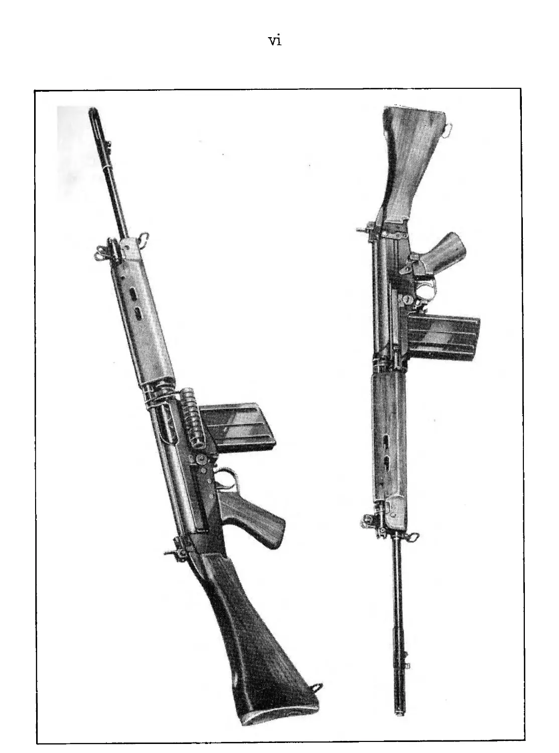
User Handbook
for the
RIFLE, 7-62mm., L1A1
Land Service
1959
(Prepared by Ministry of Supply)
By Command of the Army Council
k.w.
THE WAR OFFICE
(List of Illustrations continued)
Page
Fig, 21, Next round in position............................. 18
22. Feeding the round........... 19
23, Locking breech block ................................ 19
24. End of forward movement ............................. 19
25. Ready to fire ....................................... 20
26. Trigger pressed ..................................... 21
27. Recoil .............................................. 21
28, Hammer cocked ....................................... 21
29. Forward movement .................................... 22
30. Carrier forward ... 22
31 • Trigger released ......................... ... ... 23
32. Applied safety .................................... 24-
33 • Holding open catch ............................ 25
34» Filling magazines.......... .......................... 26
15. To remove the magazine.............................. 29
16* Rnmovo piston and spring ............................ 30
1/. To open the rifle.................................... 30
VI, Hornovo carrier and breech block ... ............ 31
o. flnpnrnl.o oander and breech block ... ....... 32
<?’. To Hl i lp the brooch block ..................... 33
51 - Tn al rip the nuigajsine ........................... 34
. I rifHifi Гог nrotio firing .......................... 34
RESTRICTED
1 he Information given In this document
Is not to be communicated, either
directly or Indirectly, to the Press or to
any person not authorized to receive it
W.O. Code
USER HANDBOOK
for the
RIFLE, 7.62 mm., L1A1
LAND SERVICE
1959
AMENDMENTS (NO. 2)
MANUSCRIPT AMENDMENTS
PAGE ii - Contents - Chapter 1 -
Section 1 under "Technical details" insert
"Method of attaching and adjusting sling .......... 2"
Section 2 under "Bayonet" insert
"Blank firing attachment ............................... 1b"
PAGE iii - Appendices (as promulgated by Arndt. 1)
Below "Appendix A" insert -
"Appendix В - Knots ................................... /(2"
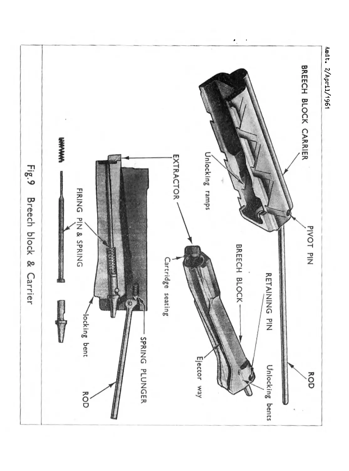
PAGE 9 - Delete existing Fig. 9 and substitute new Fig. 9
PAGE 33 - Delete existing Fig. 40 and substitute new
After page 41 (as promulgated by Arndt. 1 ) add new
VI
— 2 —
CUT-OUT AMENDMENTS
PAGE 2 After para. 4 insert new paras. 4A and 4B -
Arndt. 2/April/l96l
METHOD OF ATTACHING AND ADJUSTING SLINC
4A. Slings must be attached to the front and rear sling
swivels with the rifle closed and must not be tightened
unduly.
4B. If the sling is attached to the rifle with the rifle
broken, considerable tension will be applied to it when the
rifle is closed. Considerable tension will also be placed
on the body hinge pin, the body locking catch and lug and
the sling swivels. As this tension will damage the rifle
find may also cause the rear sling swivel to be pulled away
from the butt, this method of attaching and tightening the
sling MUST NOT be used.
PAGE 8 para. 21 Below last line add -
Arndt. 2/April/l96l
The existing firing pin will be replaced by a new
pattern (see Fig. 9) which if manufactured in two parts
to obviate breakages.
PAGE 15 Add new para. JOB -
Arndt. 2/April/l96l
BLANK FIRING ATTACHMENT (Fig. 15)
JOB. The blank firing attachment acts as a choke when
fitted to the rifle and comprises a spring, sleeve,
spindle and washer. An aperture in the spring, engages
over the bayonet lug to retain the assembly on the flash
eliminator. The spindle, which oscillates slightly, is
riveted over a washer which retains the sleeve and spring.
The assembly must be kept cleaned and lubricating of the
spindle is necessary to prevent rust.
— 3 —
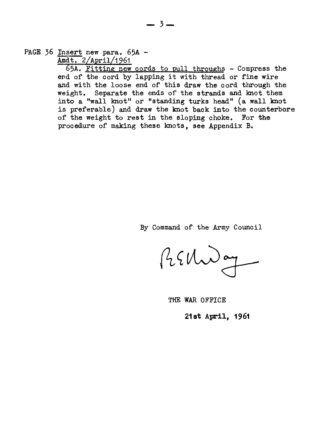
PAGE 36 Insert new para. 65A -
Arndt, 2/April/l96l
65A. Fitting new cords to pull throughs - Compress the
end of the cord by lapping it with thread or fine wire
and with the loose end of this draw the cord through the
weight. Separate the ends of the strands and knot them
into a "wall knot" or "standing turks head" (a wall knot
is preferable) and draw the knot back into the counterbore
of the weight to rest in the sloping choke. For the
procedure of making these knots, see Appendix B.
By Command of the Army Council
_______-
THE WAR OFFICE
21st April, 1961
Amdt. 2/April/-f96l
10
TRIGGER HOUSING GROUP
22. Trigger housing (Fig. Ю) - Trigger assembly, pistol grip and
body locking catch are accommodated by the housing which hinges on,
the body by means of a joint pin and retaining pin, A pistol grip
stem is formed on the underside and a return spring tube extends
from the rear face. Sea tings for the change lever plunger are
marked S and R in the left hand side. A thin plate pivots on the
inside, and is radially slotted for the retention of the hammer and
trigger pins, and drilled to receive the change lever spindle.
23. Trigger assembly (Fig. 11) - Sear and trigger operate on a
common spring, axis sleeve and pin. An elongated hole in the
sear permits backward and forward movement and the trigger is held
forward, by a plunger in the pistol group. The hammer pivots in the
forward part of the trigger housing. Its upper part is recessed
to receive the spring assembly, and two bents formed on its shank
engage the trigger sear and safety sear. The rear end of the
spring assembly seats in a recess in the crosspiece of the trigger
housing. A spring-loaded plunger in the change lever engages the
recesses of the trigger housing to hold the lever at a set position.
The change lever spindle is fitted transversely directly above the
rear arm of the trigger and part of its surface is flat. A splat
pin retains the lever in the housing during stripping.
11
2l|.. Pistol grip (Fig.11) - The grip fits over the stem of the
trigger housing and is secured by nut and bush. It is hollowed
out at the front to receive the trigger guard when the rifle is
prepared for arctic firing, and a cover, which closes that part,
is secured by a screw and two projections engaging inside the grip.
The trigger guard hinges on the cover and is hooked into the trigger
housing. The trigger plunger is retained by a plate in the top
front of the grip.
12
25. Body locking catch (Fig. 11) - Cylindrical in shape, the
catch moves horizontally being held forward by a strong spring.
The front end engages on the body to hold the rifle closed« A
recess in its left side receives the lug of the actuating lever
and a slot in its rear engages over the locating pin. The lever
is located at the rear left of the trigger housing and has a thumb
piece at its top end.
26. Backsight (Fig.11) - Of a normal aperture type, the backsight
works on an inclined bed dovetailed into the trigger housing.
An internal spring-loaded catch engages notches on the right side
of the bed to hold the sight at any range from 200 to 600 yards at
100 yard intervals; the notches are numbered from 2 to 6. A small
pin standing at the front end of the bed serves as a forward stop,
and a lip at the rear end selves as a back stop. Lateral
adjustment screws are positioned one each side of the sight bed.
BUTT GBOPP (Fig. 12)
27. The wooden butt, bored through its length, fits over the
return spring tube and to the rear of the trigger housing where it
is secured by a screw inserted underneath. It is also secured at
the rear by the screw plug which holds the return spring under
compression. A cylindrical recess in the bottom rear of the butt
accommodates the oil bottle and pullthrough, and a spring trey,
attached to the butt plate, covers the recess. Two screws secure
a metal butt plate, and the lower one also secures the rear sling
swivel.
13
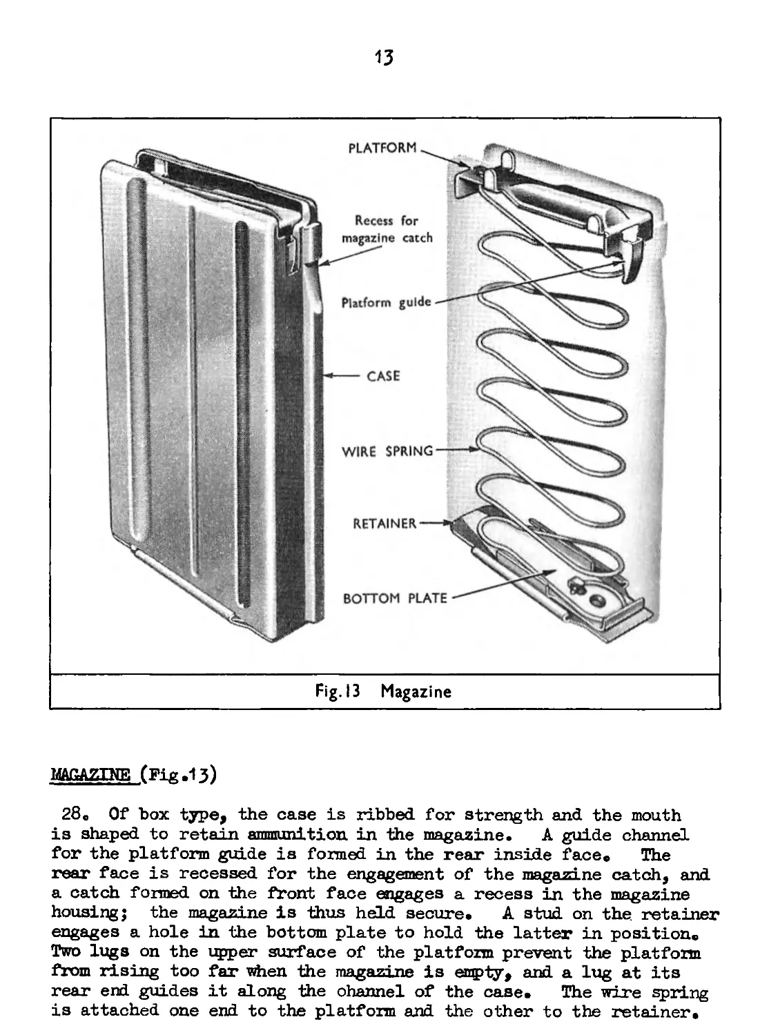
Fig. I3 Magazine
MAGAZINE (Fig .13)
28o Of box type, the case is ribbed, for strength and the mouth
is shaped to retain ammunition in the magazine. A guide channel
for the platform guide is formed in the rear inside face. The
rear face is recessed for the engagement of the magazine catch, and
a catch formed on the front face engages a recess in the magsz.i ne
housing; the magazine is thus held secure. A stud on the retainer
engages a hole in the bottom plate to hold the latter in position.
Two lugs on the upper surface of the platform prevent the platform
from rising too far when the magazine is empty, and a lug at its
rear end guides it along the channel of the case. The wire spring
is attached one end to the platform and the other to the retainer.
14
15
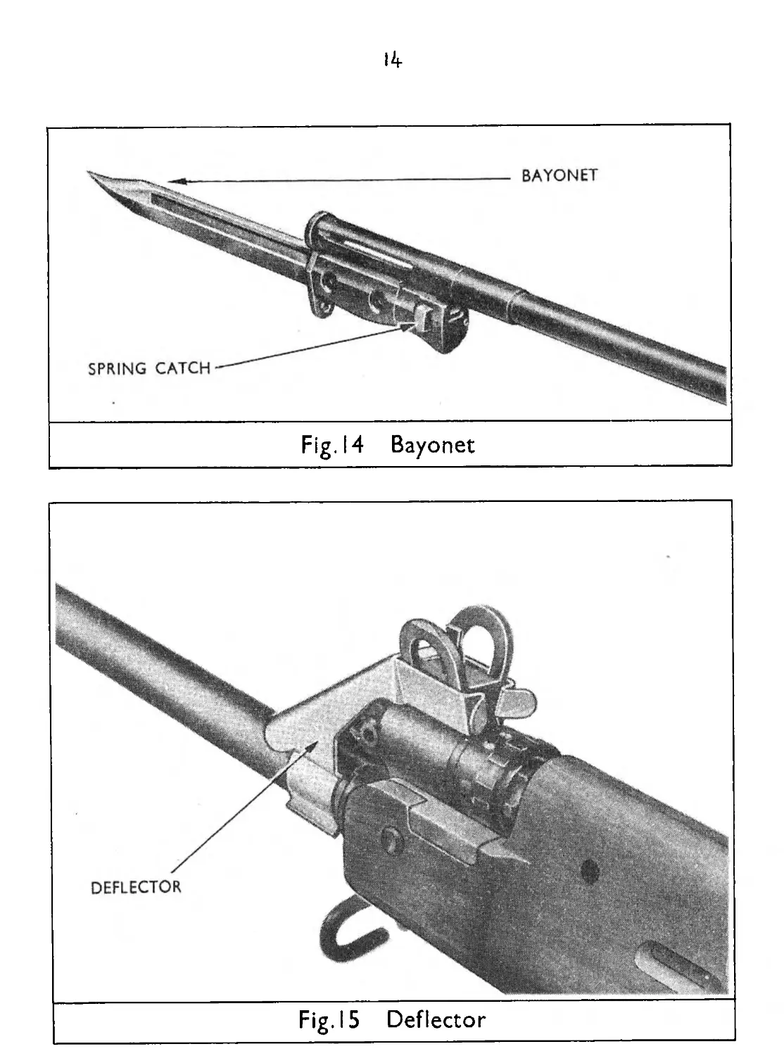
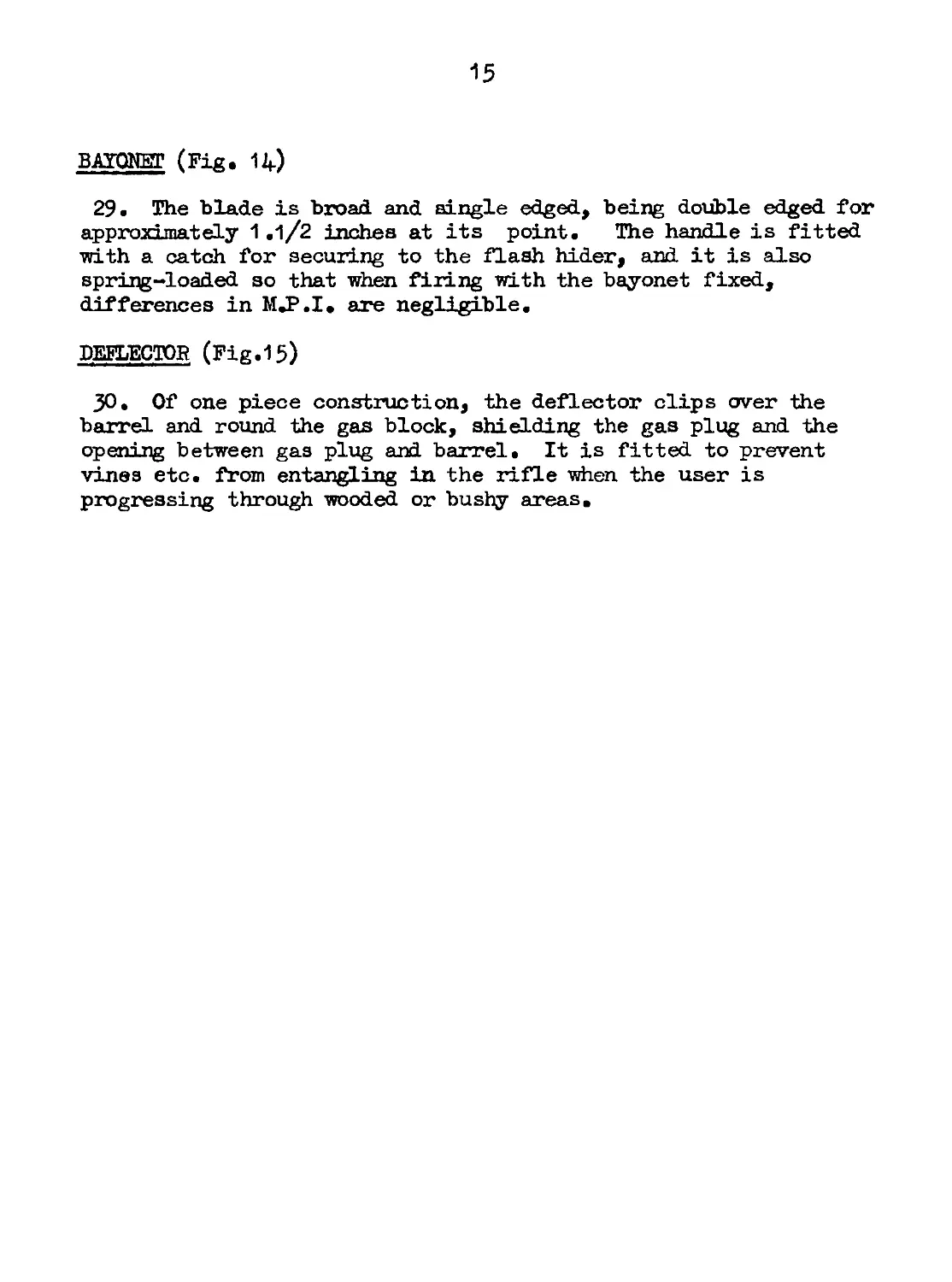
BAYONET (Fig. 1Д.)
29. The blade is broad and single edged, being double edged for
approximately 1 .1/2 inches at its point. The handle is fitted
with a catch for securing to the flash hider, and it is also
spring-loaded so that when firing with the bayonet fixed,
differences in MJ.I. are negligible.
DEFLECTOR (Fig.15)
JO. Of one piece construction, the deflector clips over the
barrel and round the gas block, shielding the gas plug and the
opening between gas plug and barrel. It is fitted to prevent
vines etc. from entangling in the rifle when the user is
progressing through wooded or bushy areas.
16
Chapter 2 - Operation
Section i - General
BACKWARD ACTION
. Firing (Fig. 16) - When, the trigger is pressed it forces the
rear end of the sear upwards disengaging the nose of the sear from
the bent of the hammer. The hammer spring, which is under
coirpression, is freed and it forces the hammer forward to strike
the firing pin, which strikes and fires the cartridge.
32. Action of gases (Fig. 17) - As the bullet passes the gas
vent in the barrel, some of the gases enter the gas vent and pass
through the gas plug into the front end of the gas cylinder to
strike the head of the piston. Some of the gas escapes through
the hole in the top of the gas block and the amount permitted to
escape is governed by the gas regulator. The piston moves to the
rear under the influence of the gases, strikes the top front of
the breech block carrier and drives it rearward. As it moves,
the piston compresses the piston spring, and, when the gases in
the cylinder are expended, the spring forces the piston forward.
33» Unlocking (Fig. 18) - During the initial movement of its
rearward travel, the carrier lifts the locking bent of the breech
block out of engagement with the locking shoulder of the trigger
housing, by means of the unlocking ramps inside the carrier.
The block is now free to move rearward with the carrier.
17
34» Ejection (Fig. 19) - The empty case, held, by the extractor,
is drawn out of the chamber as the breech block moves rearward.
The base of the сале strikes against the ejector and is ejected.
At the same time the rear bottom surface of the carrier forces the
hammer back against its spring until the upper bent of the hammer
engages on the safety sear.
18
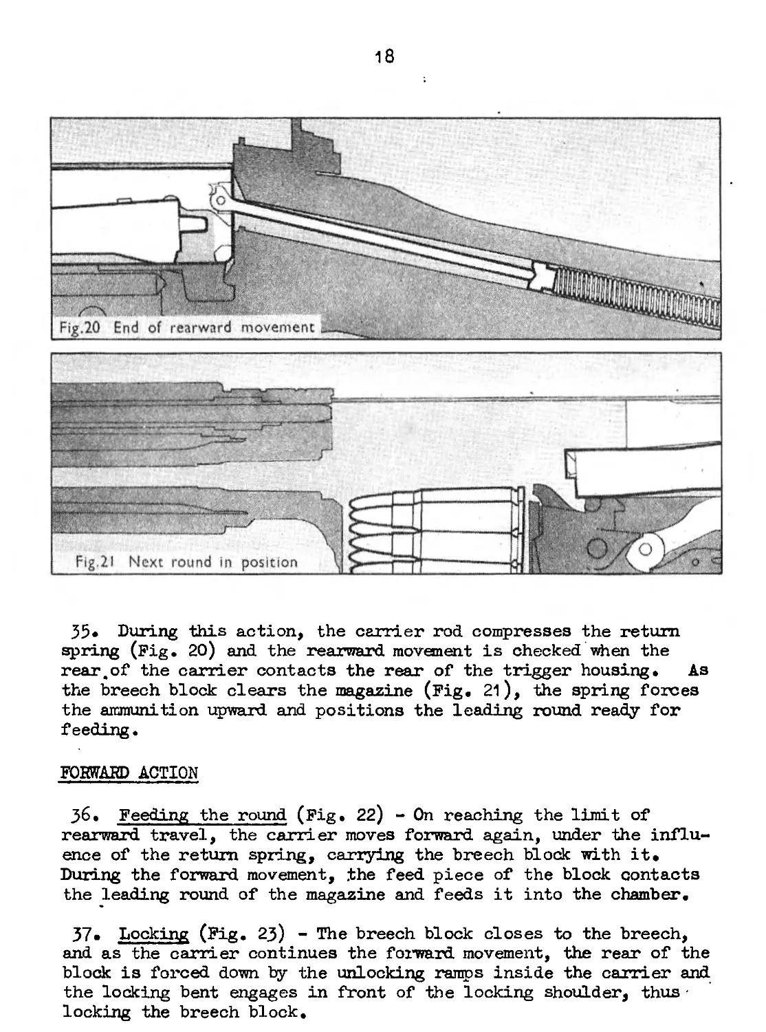
35» During this action, the carrier rod compresses the return
spring (Fig. 20) and the rearward movement is checked when the
rear,of the carrier contacts the rear of the trigger housing. As
the breech block clears the magazine (Fig. 21), the spring forces
the ammunition upward and positions the leading round ready for
feeding.
FORWARD ACTION
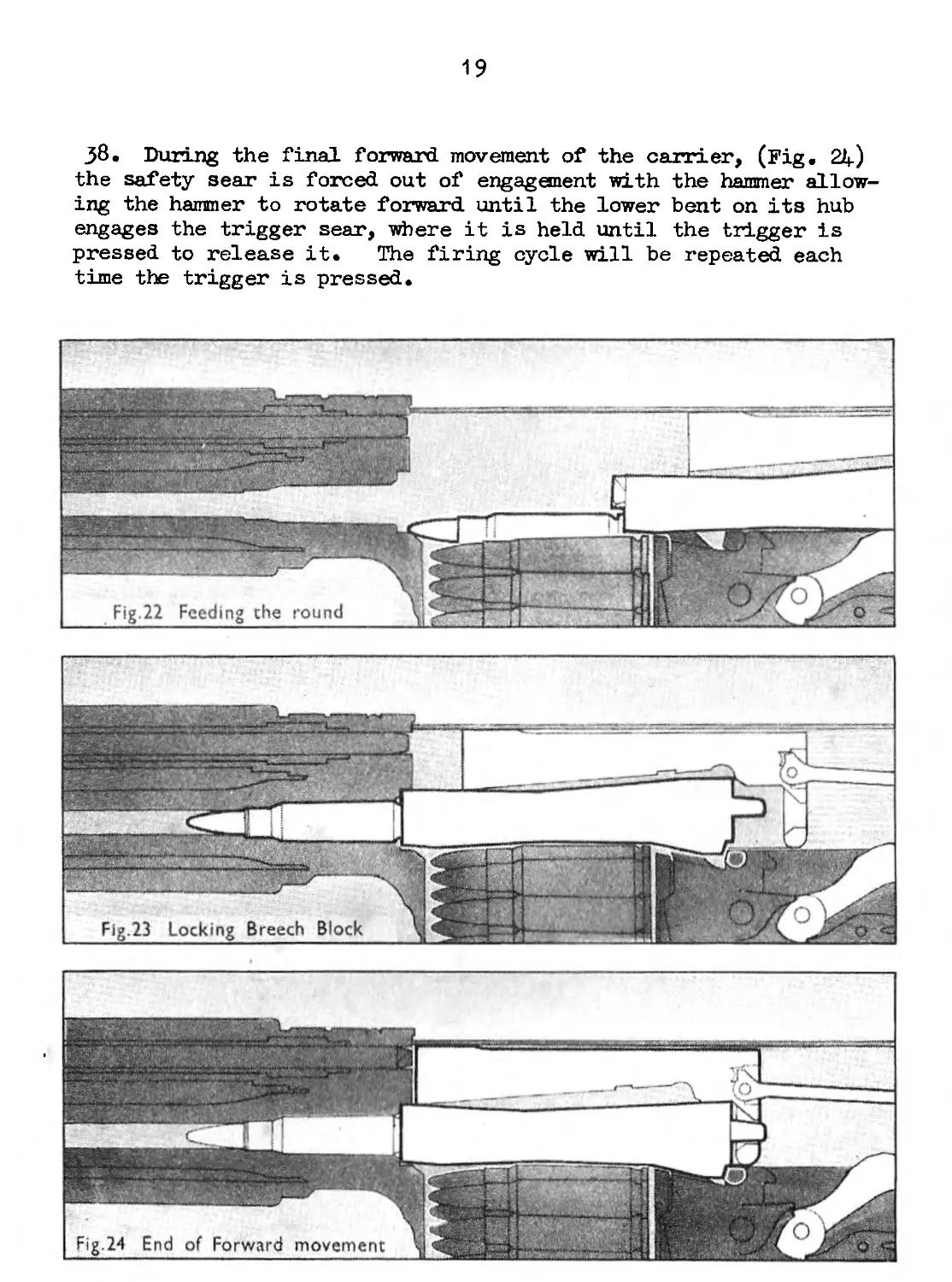
j6. Feeding the round (Fig. 22) - On reaching the limit of
rearward travel, the carrier moves forward again, under the influ-
ence of the return spring, carrying the breech block with it.
During the forward movement, .the feed piece of the block contacts
the leading round of the magazine and feeds it into the chamber.
37. Locking (Fig. 23) - The breech block closes to the breech,
and as the carrier continues the forward movement, the rear of the
block is forced down by the unlocking ramps inside the carrier and
the locking bent engages in front of the locking shoulder, thus •
locking the breech block.
19
j8. During the final forward movement of the carrier, (Fig. 2Д.)
the safety sear is forced out of engagement with the hammer allow-
ing the hammer to rotate forward until the lower bent on its hub
engages the trigger sear, where it is held until the trigger is
pressed to release it. The firing cycle will be repeated each
time the trigger is pressed.
20
TRIGGER MECHANISM
39» The change lever can be set to one of two positions, single
shots (R) or safe (s). The spindle of the change lever governs
the movement of the trigger which detemines the position of the
sear in relation to the bent of the hammer.
40. Single shot fire (Fig. 25) - When the change lever (l) is
set to single shots (r), the flat surface of the spindle is
directly opposite the tail of the trigger (2). The hammer (3) is
held by the nose of the trigger sear (4) engaging the lower bent
(5) of the hammer. The rifle is ready to fire.
41• Pressure on the trigger (Fig. 26) causes the rear of the
trigger (2) to rise, and depresses the trigger plunger (6). It
also forces upward, the tail of the sear (4) rotating the sear and
disengaging its nose from the lower bent of the hammer. The sear
spring (?) immediately pushes the sear forward along its elongated
axis (8) and at the same time the tail of the sear slips into the
step (9) on top of the trigger; the nose of the sear frictions on
the hub of the hammer. The hammer (3) rotates forward firing the
round, recoil takes place (Fig. 27), and the hammer is rotated
rearward by the carrier (1O). As the hammer reaches the limit of
rearward rotation (Fig. 28) the safety sear (11) engages the upper
bent (12) of the hammer and the trigger sear is positioned behind
the lower bent but not in contact; the weight of the cocked
hammer is borne by the safety sear.
21
24
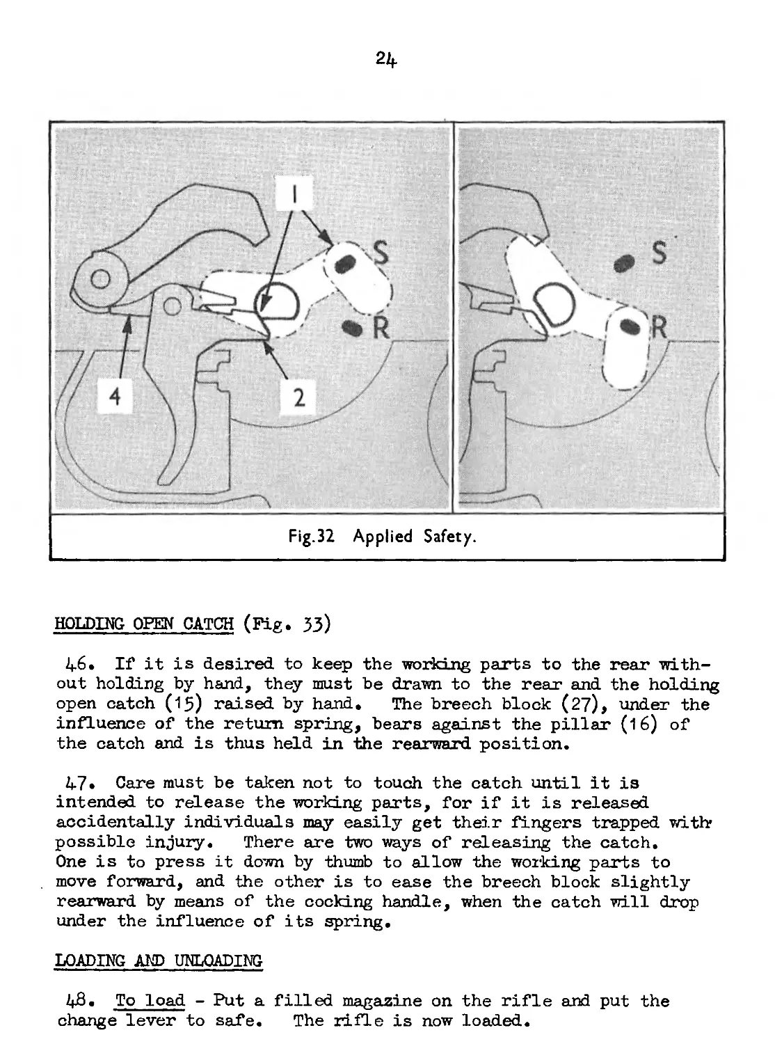
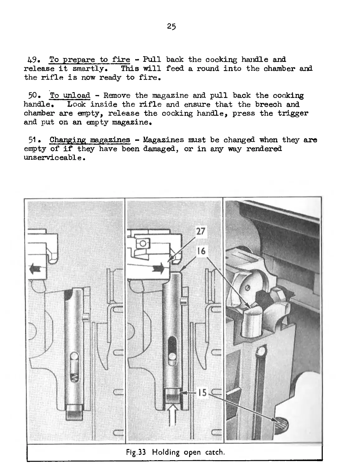
HOLDING OPEN CATCH (Fig. 33)
46. If it is desired to keep the working parts to the rear with-
out holding by hand, they must be drawn to the rear and the holding
open catch (15) raised by hand. The breech block (27), under the
influence of the return spring, bears against the pillar (16) of
the catch and is thus held in the rearward position.
47» Care must be taken not to touch the catch until it is
intended to release the working parts, for if it is released
accidentally individuals may easily get their fingers trapped with?
possible injury. There are two ways of releasing the catch.
One is to press it down by thumb to allow the working parts to
move forward, and the other is to ease the breech block slightly
rearward by means of the cocking handle, when the catch will drop
under the influence of its spring.
LOADING AND UNLOADING
48. To load - Put a filled magazine on the rifle and put the
change lever to safe. The rifle is now loaded.
25
49. To prepare to fire - Pull
release it smartly. This will
the rifle is now ready to fire.
back the cocking handle and
feed a round into the chamber and
50. To unload - Remove the magazine and pull back the cocking
handle. Look inside the rifle and ensure that the breech and
chamber are empty, release the cocking handle, press the trigger
and put on an snpty magazine.
51 . Changing magazines - Magazines must be changed when they are
empty of if they have been damaged, or in any way rendered
unserviceable.
26
FILLING MAGAZINES (Fig. 34)
52. A magazine filler is used for filling magazines. Fit it
over the mouth of the magazine, insert a five round clip into the
guides then force the rounds down into the magazine. If the
filler is not available filling by hand is simple and quick.
27
Chapter 2 - Operation
Section 2 - Stoppages and Immediate Action
STOPPAGES
53. Most stoppages are caused by adverse or abnormal conditions
and correct maintenance will do much to keep their occurrence
down to a minimum,
54. Causes of Stoppages
(a) Empty magazine - This will occur automatically, the
working parts will ronain forward,
(b) Failure to feed - In this case the breech block does not
go fully forward, which may be due to incorrect handling
when the cocking handle is not released smartly. It
may also be due to a dirty or damaged round, dirty
cl iamb er, damaged magazine or some obstruction fouling the
face of the breech block carrier or rear face of the
breech.
(c) Hard extraction - The empty case may be in, or partially
in the chamber due to a dirty round or a dirty chamber,
and, because of the extra work, the gases are not able
to perform correctly. Manual operation will cause the
case to be extracted, and once the dirty round is cleared
and the chamber cleaned, the rifle should give no further
trouble.
(d) Friction - This stoppage may result from a number of
causes such as, dirt, fouling in the cylinder and on the
piston, or lack of lubrication on the working parts.
The breech block may be anywhere along the body and manual
operation may remedy the stoppage temporarily but only
cleaning will completely cure it.
(e) Insufficient gas - This stoppage should only occur when
conditions are either adverse or abnormal, or when an
incorrect gas setting is used. Adjustment of the
regulator is explained in Chapter 3, Section 2 , para. 72.
28
(f) Obstruction in the chamber - This is caused by a separated
case, the forward end of which remains in the chamber.
The next round fed will go partially into the chamber,
and the breech block will be stopped about half-way
forward. The separated case is removed by the ruptured
cartridge extractor, commonly called the clearing plug.
(g) Broken or worn parts - When investigating the cause of
such a stoppage, looking into the body and chamber should
disclose to the firer which part is a fault. A case in
the chamber with the cap struck indicates a broken
extractor or extractor spring, and an unfired round drawn
out of the chamber on cocking the rifle indicates a
broken firing pin. It is the responsibility of an
armourer to change broken parts, but the user may change
the firing pin, and the extractor and spiring.
IMMEDIATE ACTION
55» Most of the stoppages which may occur can be remedied by the
user applying immediate action, i.e, pull the cocking handle back
about half-way, release it smartly and carry on firing. If after
this, the rifle fails to fire remove the magazine and oock the
rifle. If the magazine is empty, change it, but if there are
rounds in it put it back, cock the rifle and continue firing.
Should stoppages recur, put the change lever to safe, adjust for
more gas and continue firing; repeat the procedure until the rifle
fires correctly. Continued recurrence of stoppages indicate broken
parts or»very bad fouling. Unload the rifle, put the change lever
to safe, strip the rifle and examine it for broken or damaged parts.
If it is fouled, clean it. Assemble the rifle, load and continue
firing.
56. Under desert warfare or extreme dusty conditions, less
stoppages due to friction will occur if the magazine is filled with
15 rounds only.
29
Chapter з - Servicing and Adjustment
Section i - Stripping and Assembling
STRIPPING-
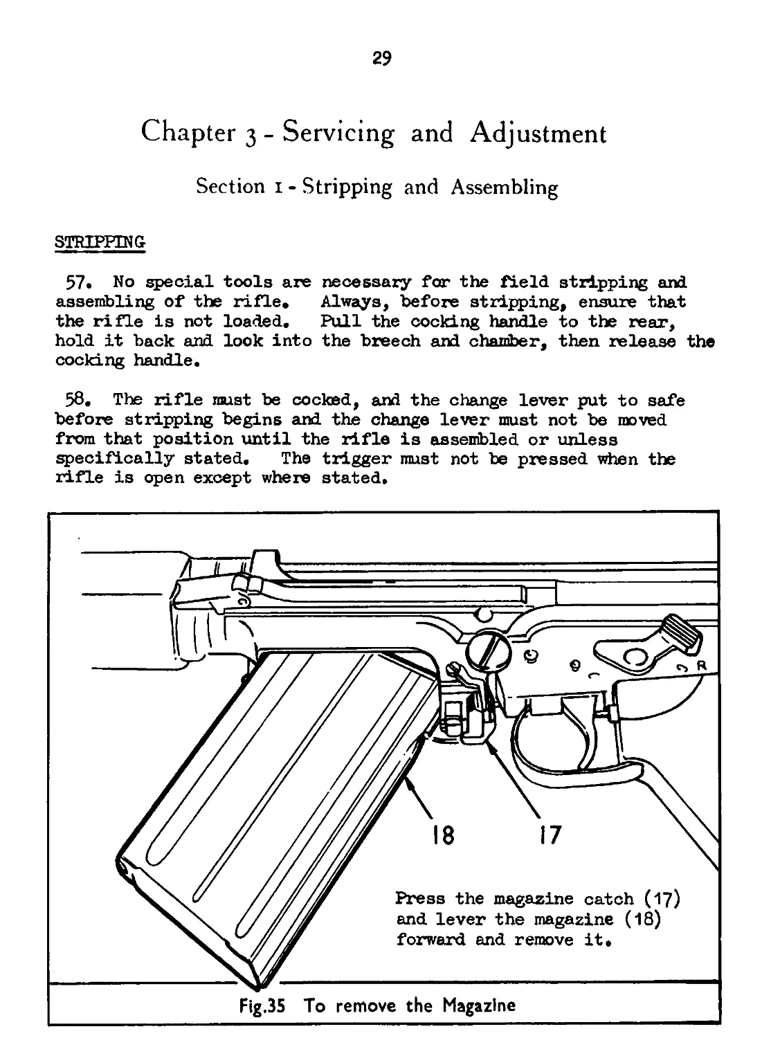
57. No special tools are necessary for the field stripping and
assembling of the rifle. Always, before stripping, ensure that
the rifle is not loaded. Pull the cocking handle to the rear,
hold it back and look into the breech and chamber, then release the
cocking handle.
58. The rifle must be cocked, and the change lever put to safe
before stripping begins and the change lever must not be moved
from that position until the rifle is assembled or unless
specifically stated. The trigger must not be pressed when the
rifle is open except where stated.
32
27
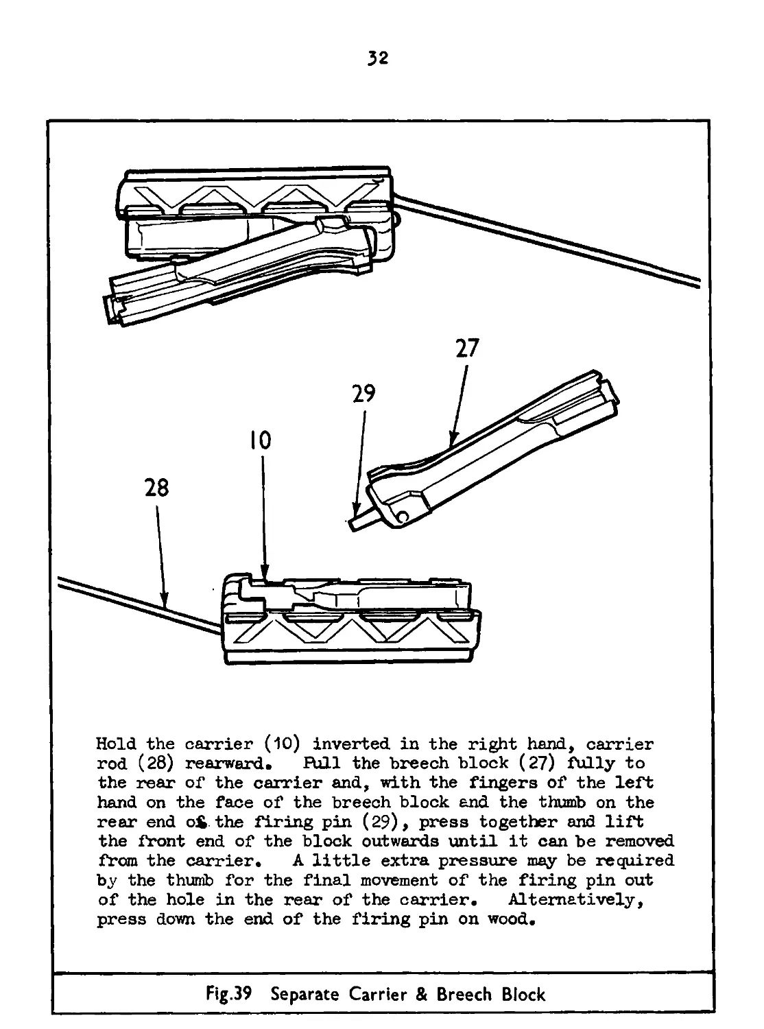
Hold the carrier (10) inverted in the right hand, carrier
rod (28) rearward. RjII the breech block (27) fully to
the rear of the carrier and, with the fingers of the left
hand on the face of the breech block and the thumb on the
rear end oS the firing pin (29), press together and lift
the front end of the block outwards until it can be removed
from the carrier. A little extra pressure may be required
by the thumb for the final movement of the firing pin out
of the hole in the rear of the carrier. Alternatively,
press down the end of the firing pin on wood.
Fig.39 Separate Carrier & Breech Block
У5
Press the firing pin (29) forward against the spring (30)
and push out the retaining pin (31). Ease the firing pin
and spring out to the rear and separate them.
Place the pin of the combination tool in the hole of the
extractor plunger (32). Place the rear end of the breech
block (27) against the body, hold it firmly, and pull the
combination tool back until the extractor (33) can be
removed. Remove the extractor plunger (32) and spring
(34).
Fig.40 To strip the Breech Block
The magazine should only be stripped when necessary for
cleaning purposes or to replace broken or damaged parts.
Excessive stripping must be avoided to reduce wear on the
bottom plate. Press in the retainer stud (35) clear of
the bottom plate (36) and push the bottom plate rearward
clear of the magazine (18), and at the same time control
the spring to prevent it from flying out. Withdraw the
retainer (37) spring (38) and platform (39)»
Fig.4l To strip the Magazine
Remove the screw (40) of the pistol grip cover (4-1), remove
the cover and unhook the trigger guard (42) from the
trigger housing. Fold the trigger guard on to the rear
fsce of the cover, replace the cover on the pistol grip
with the trigger guard in the folded position and secure it
with the screw. A gloved or mitten covered hand can now
operate the trigger unhampered by the trigger guard.
Fig.42 Prepare for Arctic Firing
35
ASSEMBLING
59» To assemble the breech block - Put the extractor spring and
plunger in their housing in the breech block. Place the pin of
the combination tool in the hole in the plunger and the real1 of
the breech block against the body. Hold firmly, pull the
combination tool back until the extractor can be inserted, ease
the plunger forward until it engages the extractor to retain it to
the breech block. Insert the firing pin and spring into the
breech block -with the recess, in the rear end of the pin,
uppermost. Press forward until the recess is in line with the
retaining pin holes, and push in the retaining pin.
60. To replace the breech block and carrier - Place the rear end
of the firing pin Ln the hole in the carrier, press rearward and
close the block into the carrier. Push the breech block fully
forward along the carrier so that the locking bent is raised clear
of the lower surface. Engage the guide ribs of the carrier in the
grooves in the body and push the carrier fully forward. During
this action, if the thumb is placed behind the breech block it will
prevent the block from sliding rearward so causing a jam. Slide,
the body cover into position and close the rifle.
61. To replace the piston and spring - Replace the spring on the
piston, it will go on either way, and engage the end coils behind
the bulge on the piston where it will be retained. Put the piston
and spring into the cylinder and push it fully home with the gas
plug in the position it was removed. Press in the plunger of the
gas plug as far as it will go and turn the plug until the narrow
recess is uppermost. Release the plunger and ensure that it is
properly engaged in the recess in the gas block.
62. To assemble the magazine - Place the platform in the bottom
end of the case with the guide lug engaged in the guide channel.
Follow in with the spring and retainer. Compress the spring and
replace the bottom plate ensuring that the retaining stud is
engaged in the hole in the bottom plate. Move the platform up and
down a few times to ensure that the platform and spring operate
properly.
63» When field assembling is completed the rifle should be tested
by putting the change lever to R and then operating the working
parts and the trigger.
Chapter 3 Servicing and Adjustment
Section 2 Care and Cleaning
CLEANING MATERIALS
64. Care must be taken in the treatment of the weapon to keep it
in a condition that will give perfect functioning of the mechanism
and continued accuracy. It is essential that the entire mechanism
is kept cleaned and properly lubricated so that the weapon may
operate easily, and to prevent stoppages. The following tools and
accessories are issued for the maintenance of the weapon:-
(a) Oil bottle.
(b) Oil can.
Sc) Chamber and gas cylinder cleaning brash.
d) Rifle cleaning brush.
(e) Barrel scouring brush.
(f) Bore cleaning brush.
(g) Cleaning kit container.
(h) Ruptured cartridge extractor (Clearing plug).
(j) Bore and gas cylinder cleaning rod, with extensions.
(k) Combination tool.
(1) Extractor removing tool.
(m) Spare parts wallet.
(n) Pullthrough.
(o) Flannelette.
(p) Graphited grease in 3/4 oz. tubes (Grease XG 340).
65» The pullthrough is made up of a metal weight and a cord.
The weight is pointed and is also used to remove fouling from the
gas plug. The cord has two loops, one situated about one third
along its length for use with the flannelette, and one at the end
to assist in the removal of the cord should it jam in the bore or
the cylinder.
66» The oil bottle is the normal type with the spoon, and under
normal conditions it must be kept filled with Oil ОС 600 (Oil A).
It is carried, with the pullthrough, in the butt where it must be
put in screw top first followed by the pullthrough, the cord of
which should be coiled tightly.
37
67• The cleaning rod has an eye for use with flannelette, nn<l
the end of it is screw-threaded for the attachment of a biunh.
The rod is in sections for packing in the container and for
extending its length.
68. The combination tool has a pin formed on its forward ent
wnich is used for removing the extractor, and it is fitted with nn
adaptor for the chamber cleaning brush.
69. Normal service flannelette is used for cleaning the bore anti
cylinder, and rags or cotton waste should be used for cleaning the
remaining parts of the rifle.
NO ABRASIVE MATERIAL OF ANY KIND
MUST HE USED TO CLEAN THE RIFLE
BEFORE FIRING
70. The rifle must be field stripped, and all exposed parts dry
cleaned and examined for wear and. burrs. Worn parts must be
exchanged, and burrs must be removed, by the armourer. Magazines
and ammunition must be cleaned and examined for damage.
71. Farts should be lubricated or left dry as under:-
LUBRICATED LEFT DRY
Piston spring Inside breech block carrier Guide ribs Breech block Locking bent recess Guide grooves Holding open catch Magazine catch Body locking catch Trigger mechanism Barrel Gas cylinder Gas plug Piston, especially the heed and between the rings Exterior of weapon Face of breech block Magazine platform Sights
38
72• The gas regulator must he adjusted for correct functioning.
Adjustment may vary with different rifles and the user must learn
from experience, the correct setting to be used under normal
circumstances. As a basis, No. 6 setting gives a fair balance of
gases, and the regulator may be adjusted either way as required.
The numbers 1 to 12, marked on the outer surface of the regulator
indicate the setting, but if these numbers are not distinguishable
the clicking device is the only means of determining the exact
setting of the regulator. There are 12 clicks for the full turn
of the regulator i.e. one click per setting.
DURING FIRING
73 . Every opportunity should be taken to clean, examine and
lubricate the rifle during lulls in firing, special attention
being given to gas affected parts.
74 . To avoid overheating the round in the chamber during periods
of rapid fire, the breech should be opened, whenever possible,
and the breech block held back on the holding open catch.
75 • It may be necessary during firing to readjust the gas
regulator. The rifle must first be unloaded or the change lever
set to safe, and the gas regulator turned, one click at a time,
with the combination tool or the nose of a round, to correct the
balance. If stoppages have occurred the regulator should be
screwed forward, but if excessive hammering on the shoulder of the
firer has been experienced, it should be screwed rearward.
AFTER FIRING
76 . Field strip the rifle, and, using the cleaning accessories
ana slightly oiled flannelette, clean out the barrel and cylinder.
Dry clean them and re-oil. Clean the remainder of the rifle
paying special attention to the gas affected parts. The barrel
and cylinder must be cleaned carefully for a few days after firing.
Magazines must be cleaned and re-oiled and, if the bayonet has been
used it must be cleaned oarefully and lightly oiled.
ABNORMAL CONDITIONS
77 . When preparing the rifle for use voider abnormal conditions,
all working parts must be thoroughly dry cleaned before being
treated with special lubricant. It will help in the initial
39
stages of firing if the working parts are hand operated sharply
backward and forward a few times before loading takes place.
Magazines must also be cleaned and lubricated. The gas regulator
may have to be adjusted to give more gas.
78 • Lubricants to be used for various temperatures;-
Use Temperature Lubricant
All working parts in body and trigger mechanism. Below 0°F. 0°F. to tf)°F. AjO°F. to 80°Б Over 80°F. Normal 50/50 Mixture of Oil, OX 13 and Kerosine В Oil, OX 13 . Oil, OX 52 Oil, OX 52 Emergency substitute Vaporising oil in lieu of Kerosine Oil, OM 13 Oil, OM 58 Oil, OX 13 Oil, OM 58 Grease, LG 320
79. lubricants to be used for special purposes: -
Purpose Lubricant
Storage Beach landings Dusty/sandy climates Preservative, PX 11 or PX A Grease, LG 38O or Grease, LG 280 Graphited grease, XG 340
40
Chapter з - Servicing and Adjustment
Section 3 - Zeroing
CORRECTIONS
80. The rifle is zeroed before issue to the user but may require
adjustment to suit the individual. Adjustments to the rifle will
be carried out by R.E. M.E. or qualified personnel only.
81. Elevation - Errors in elevation are corrected by screwing the
foresight up or down. If it is screwed down the MPI will be
moved up, and vice versa. One complete turn of the foresight
will mo vs the MPI vertically, 1/2 in. at 25 yards, and 2 in. at
100 yards.
82» Direction - Errors in direction are corrected by moving the
backsight laterally. If it is moved to the left the MPI will be
moved to the left, and vice versa. To move the backsight to the
left, loosen the adjusting screw on the left of the sight block
and screw up the adjusting screw on the right, thus moving the
sight bed, along its dovetail, to the left. One complete turn
of the adjusting screw moves the MPI laterally 1.1/8 in. at
25 yards, and 4.1/2 in. at 100 yards.
83. When corrections have been made, and before shooting
commences, ensure that all screws are tight.
TESTING
84. The rifle should be zeroed at 100 yards with the sight set to
200 and with the finer lying resting the forearm only against a
sandbag. The MPI should fall between 3 in. and 5 in. above the
point of aim vertically, and central laterally.
85. If the rifle is zeroed at 25 yards, which should be avoided
ii possible as the longer" range gives more satisfactory results,
the procedure is as above, but the MPI should fall between 3/4 in.
and 1.1/4 in. above the point of aim vertically, and central
laterally.
RESTRICTED
6788-32607-8200-l3M-4/59(M.F.P.)
Aiuilt.. .'/April/1961
Fig.44 Wall Knot
Fig.45 Crown Knot on Wall Knot
Fig.46 Man-Rope Knot
Fig.47 Standing Turks Head