/


Text
Sustainable Aviation
Can Ozgur Colpan
Ankica Kovač Editors
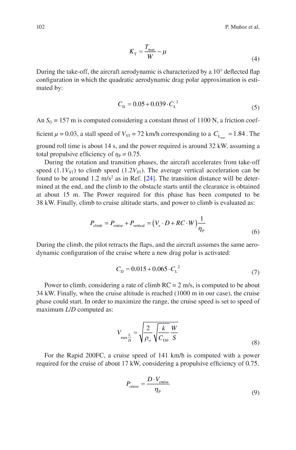
Fuel Cell and
Hydrogen
Technologies
in Aviation
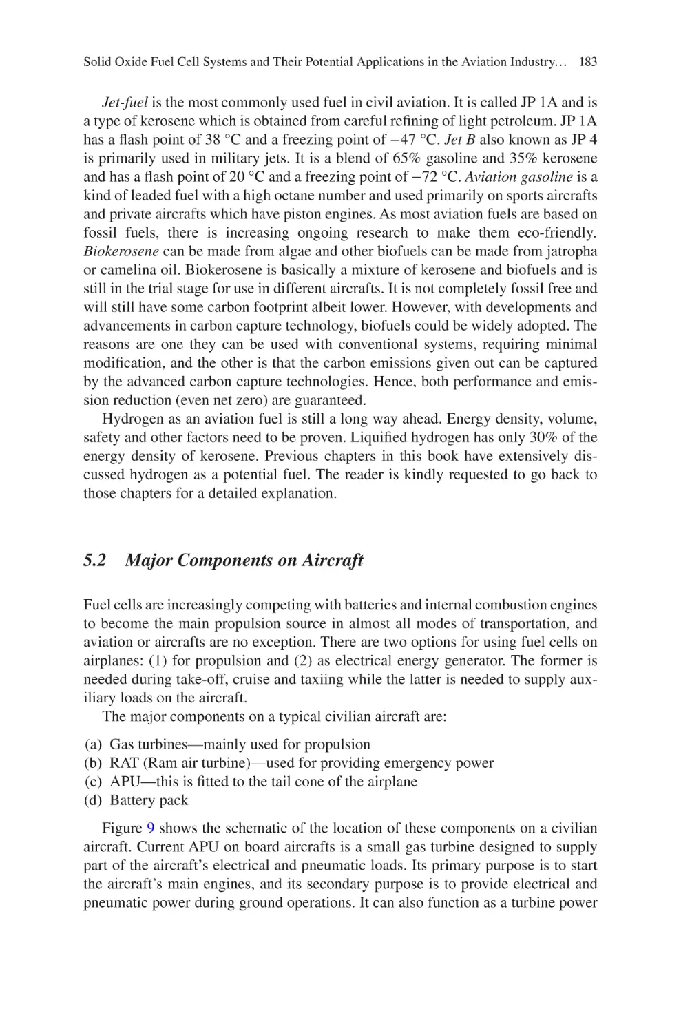
Sustainable Aviation
Series Editors
T. Hikmet Karakoc , Faculty of Aeronautics and Astronautics
Eskisehir Technical University
Eskisehir, Turkey
C Ozgur Colpan , Department of Mechanical Engineering
Dokuz Eylül University
Buca, Izmir, Turkey
Alper Dalkiran , School of Aviation
Süleyman Demirel University
Isparta, Turkey
The Sustainable Aviation book series focuses on sustainability in aviation,
considering all aspects of the field. The books are developed in partnership with the
International Sustainable Aviation Research Society (SARES) and include
contributed volumes consisting of select contributions to SARES international
symposiums and conferences, monographs, and professional books focused on all
aspects of sustainable aviation. The series aims at publishing state-of-the-art
research and development in areas including, but not limited to:
•
•
•
•
•
•
Green and renewable energy resources and aviation technologies
Aircraft engine, control systems, production, storage, efficiency, and planning
Exploring the potential of integrating renewables within airports
Sustainable infrastructure development under a changing climate
Training and awareness facilities with aviation sector and social levels
Teaching and professional development in renewable energy technologies and
sustainability
Can Ozgur Colpan • Ankica Kovač
Editors
Fuel Cell and Hydrogen
Technologies in Aviation
Editors
Can Ozgur Colpan
Department of Mechanical Engineering
Dokuz Eylül University
Izmir, Turkey
Ankica Kovač
University of Zagreb
Faculty of Mechanical Engineering
and Naval Architecture
Zagreb, Croatia
ISSN 2730-7778 ISSN 2730-7786 (electronic)
Sustainable Aviation
ISBN 978-3-030-99017-6 ISBN 978-3-030-99018-3 (eBook)
https://doi.org/10.1007/978-3-030-99018-3
© The Editor(s) (if applicable) and The Author(s), under exclusive license to Springer Nature
Switzerland AG 2022
This work is subject to copyright. All rights are solely and exclusively licensed by the Publisher, whether
the whole or part of the material is concerned, specifically the rights of translation, reprinting, reuse of
illustrations, recitation, broadcasting, reproduction on microfilms or in any other physical way, and
transmission or information storage and retrieval, electronic adaptation, computer software, or by similar
or dissimilar methodology now known or hereafter developed.
The use of general descriptive names, registered names, trademarks, service marks, etc. in this publication
does not imply, even in the absence of a specific statement, that such names are exempt from the relevant
protective laws and regulations and therefore free for general use.
The publisher, the authors and the editors are safe to assume that the advice and information in this book
are believed to be true and accurate at the date of publication. Neither the publisher nor the authors or the
editors give a warranty, expressed or implied, with respect to the material contained herein or for any
errors or omissions that may have been made. The publisher remains neutral with regard to jurisdictional
claims in published maps and institutional affiliations.
This Springer imprint is published by the registered company Springer Nature Switzerland AG
The registered company address is: Gewerbestrasse 11, 6330 Cham, Switzerland
Preface
The aviation sector is significantly responsible for greenhouse gas and air pollutant
emissions. Despite the efficiency improvements in aircraft engines, the industry
growth rate is higher; thus, the emissions continue to increase annually. Many countries and organizations have already agreed on reducing these emissions substantially in the near future. Hence, using clean fuel and technologies in aviation plays
a key role in achieving these goals. Electric aircraft using batteries, provided that
electricity used to charge the batteries is produced from renewables, biofuel or synthetic fuel-fed engine-powered aircraft, and hydrogen-fed fuel cell-powered aircraft
seem to be the most promising options in this regard. Significantly, the use of hydrogen energy is increasing rapidly in the aviation sector and several new prototypes
and products are released continuously.
This book gives an overview of the current status and future directions on the use
of hydrogen and fuel cell technologies in aviation and their potential to reduce the
environmental impact of aircraft. Their technological and economic feasibility and
requirements in the aircraft design and airport infrastructure are discussed. Different
hydrogen storage technologies that can be used in aircraft, including compressed
gaseous hydrogen, cryogenic compressed hydrogen, cryogenic liquid hydrogen,
metal hydride hydrogen, chemical hydrogen, organic hydrogen, and adsorption
hydrogen storage, are covered. As liquid hydrogen is quite promising, especially for
long-range flights, a separate section is devoted to this fuel to show the status and
trend of its use in aviation. Infrastructure, logistics, and safety requirements to operate hydrogen-powered aircraft at an airport before they perform commercial flights
are also handled in this book. Applications of fuel cells in unmanned aerial vehicles
and passenger aircraft and several topologies that can be used, are addressed.
Optimizing the sizing and energy management of fuel cell-based aircraft powertrains is also important in terms of achieving long range and operating with low
cost. This book also describes a method to obtain an optimized energy management
strategy for fuel cell-powered aircraft. The use of solid oxide fuel cells as auxiliary
power units and a hybrid propulsion unit in conjunction with gas turbines is also
discussed in detail.
v
vi
Preface
This book is expected to guide researchers, scientists, engineers, and graduate
students in the selection, design, and assessment of hydrogen storage and fuel cell
technologies for various aircraft types. We would like to thank the Sustainable
Aviation Research Society (SARES) for giving us the opportunity to publish this
book, Springer editorial team for helping and guiding us in each step of the preparation of the book, and all chapter authors and reviewers for their excellent contributions in the success of this book.
Izmir, Turkey
Zagreb, Croatia
Can Ozgur Colpan
Ankica Kovač
Contents
Hydrogen Storage Technology for Aerial Vehicles���������������������������������������� 1
Dirk Kastell
Liquid
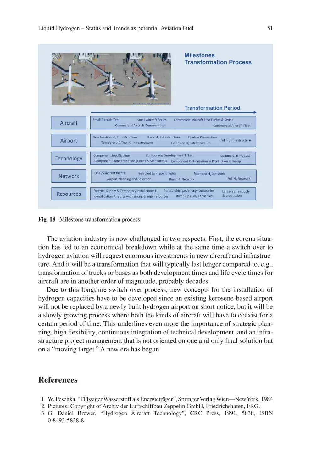
Hydrogen – Status and Trends as potential Aviation Fuel�������������� 23
Michael Bracha
Fuel
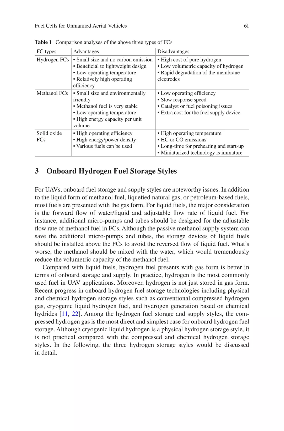
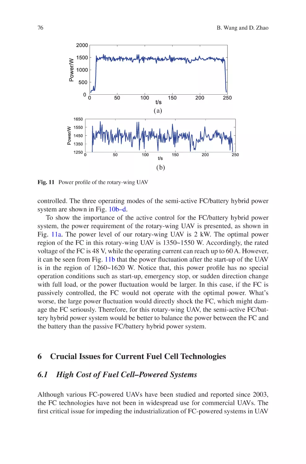
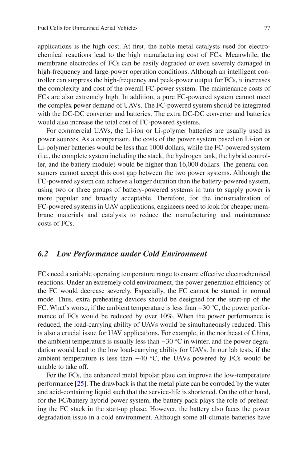
Cells for Unmanned Aerial Vehicles������������������������������������������������������ 55
Bin Wang and Dan Zhao
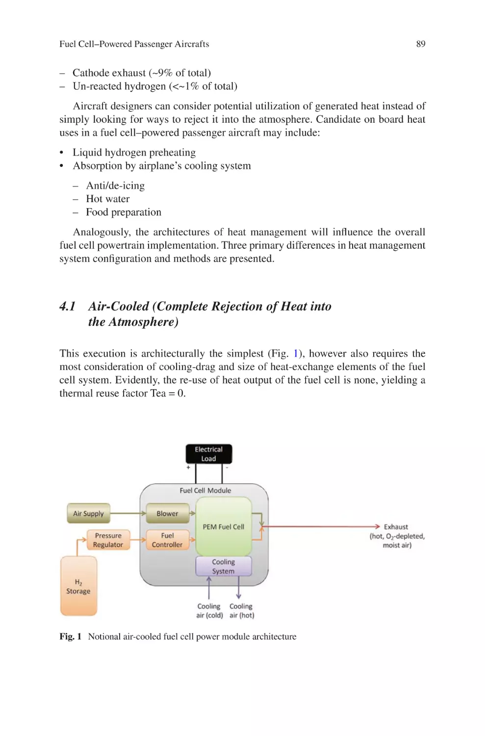
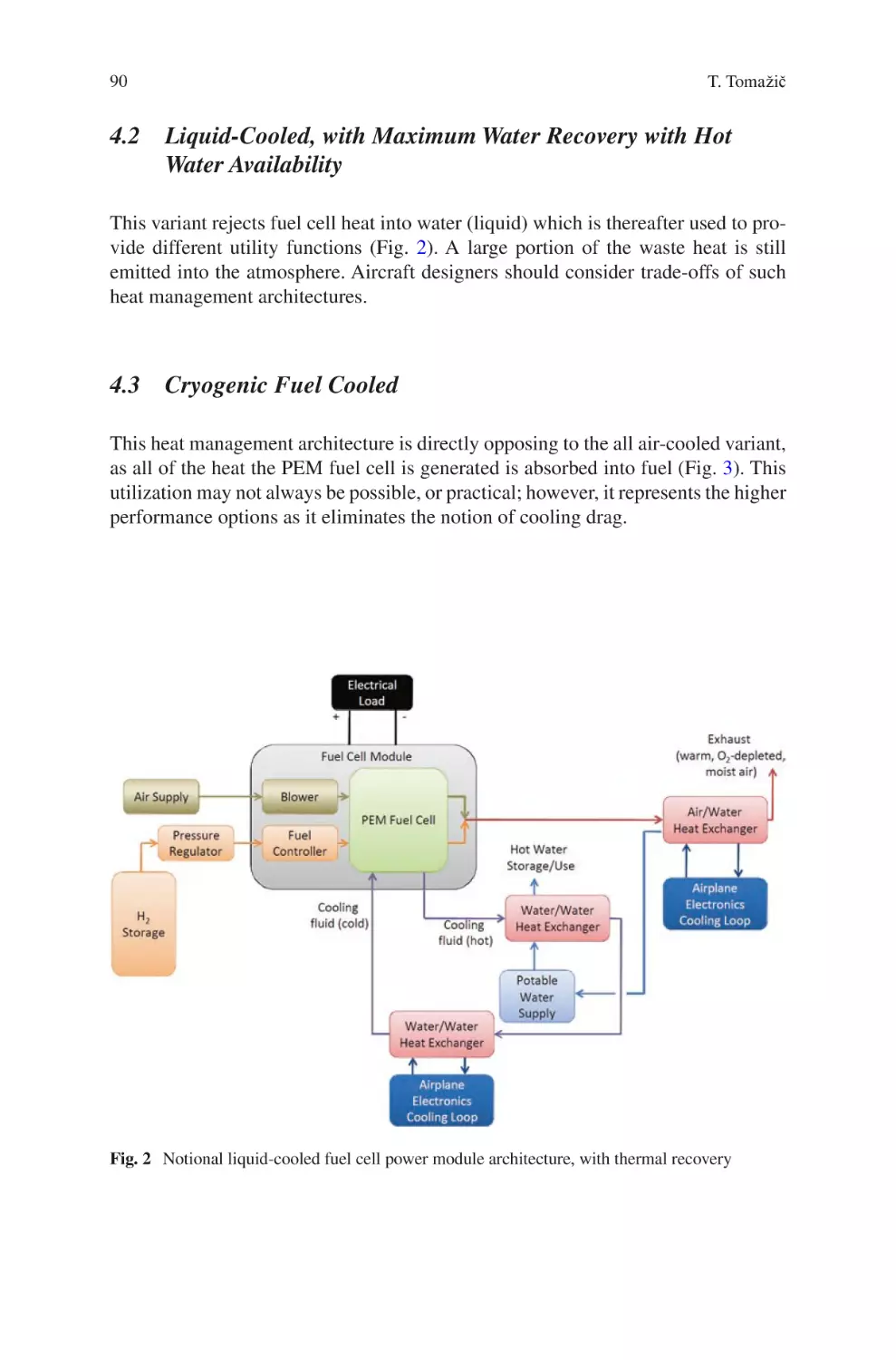
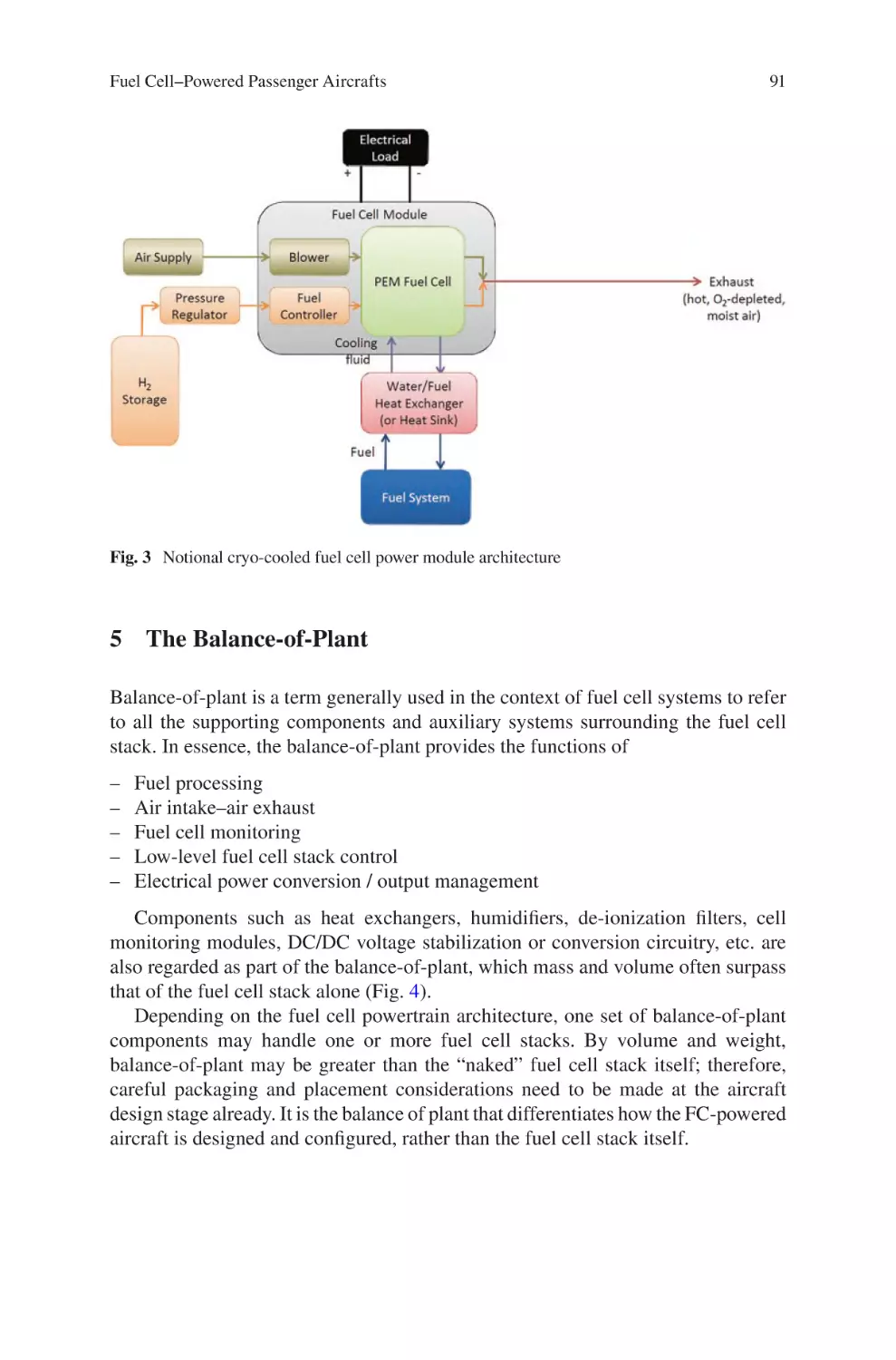
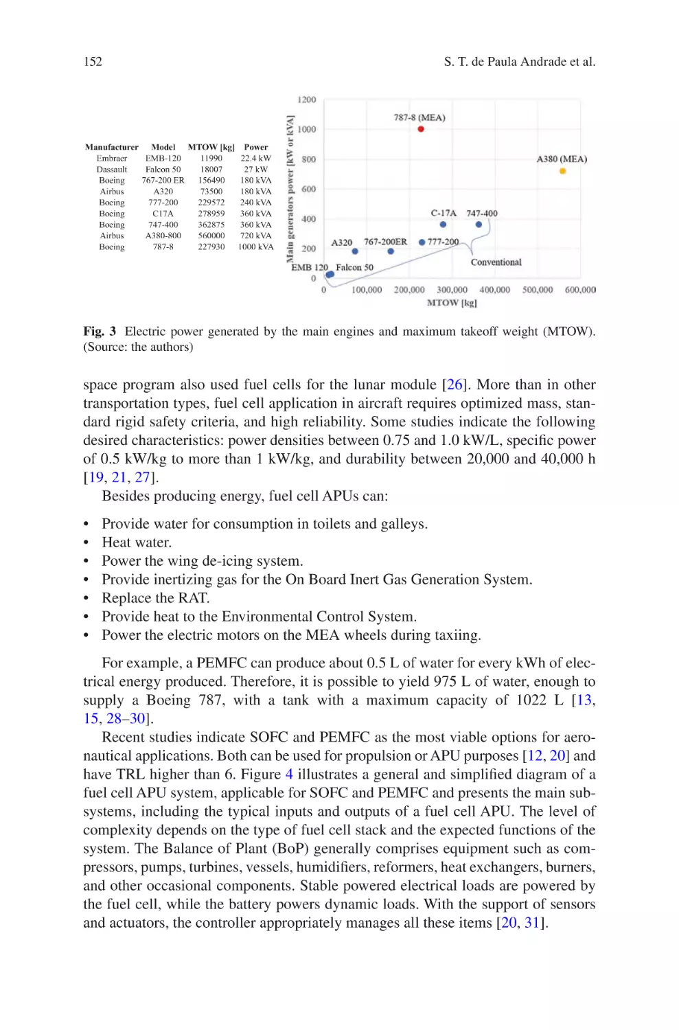
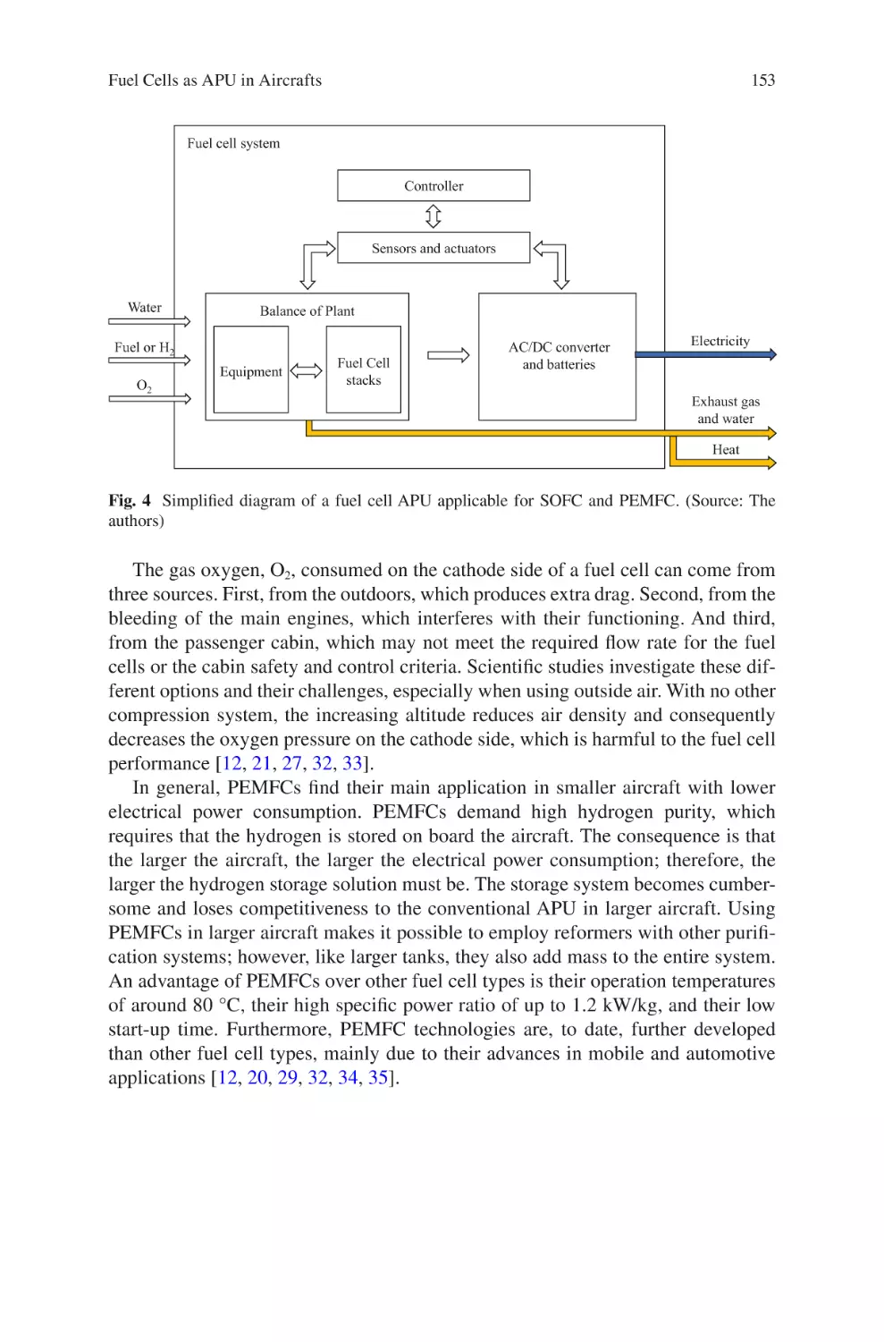
Fuel Cell–Powered Passenger Aircrafts �������������������������������������������������������� 83
Tine Tomažič
Energy
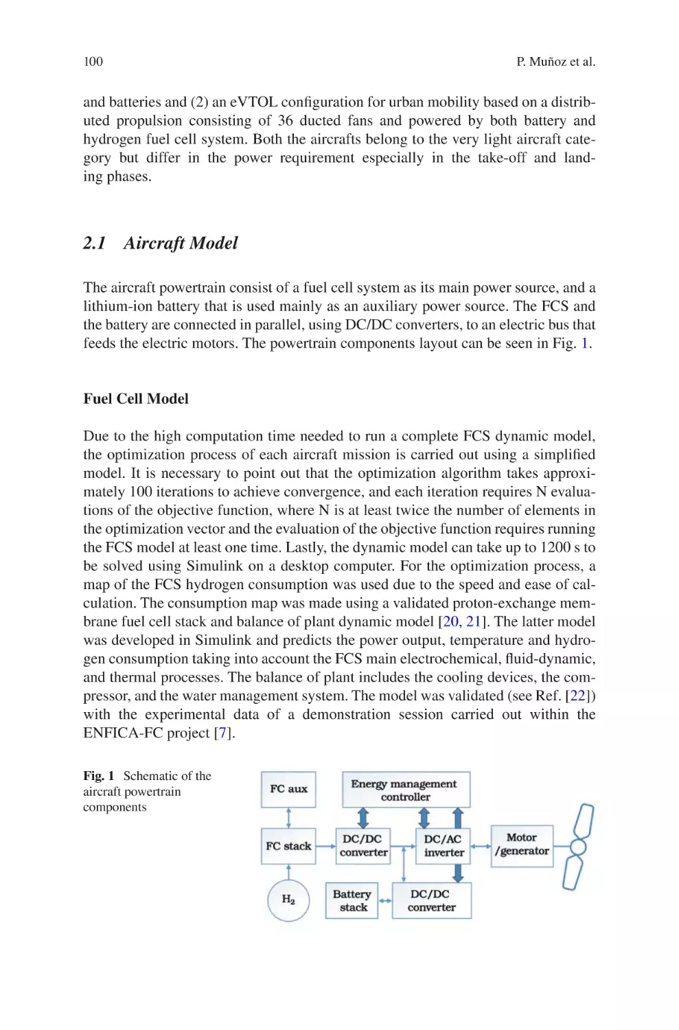
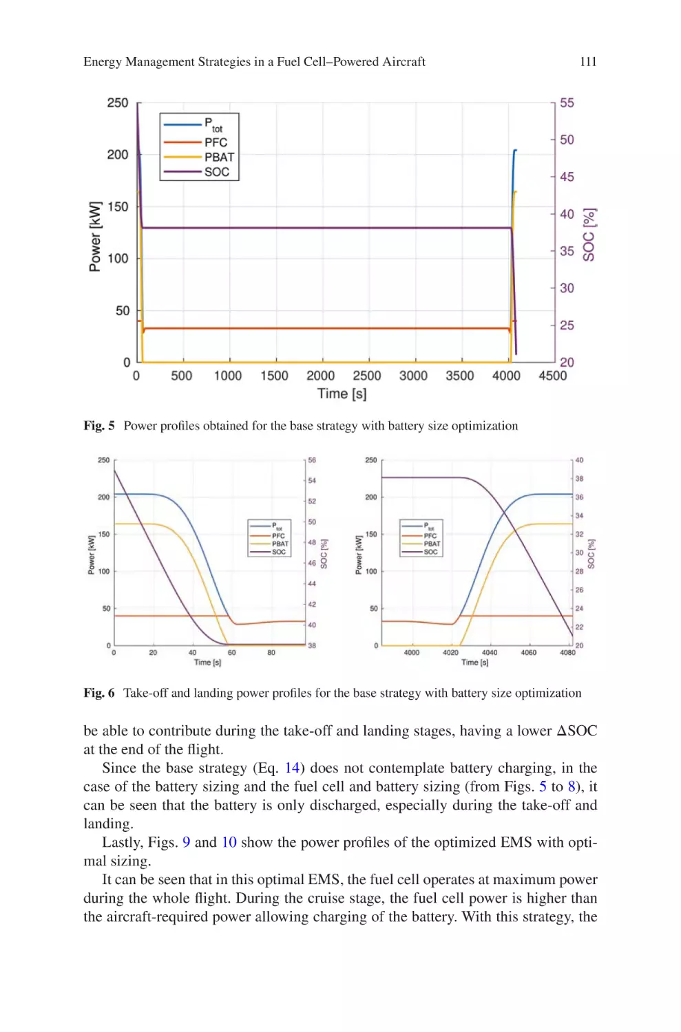
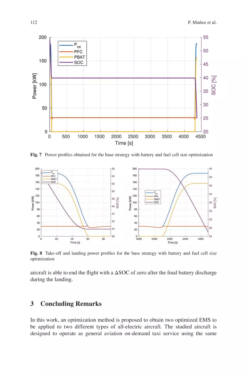
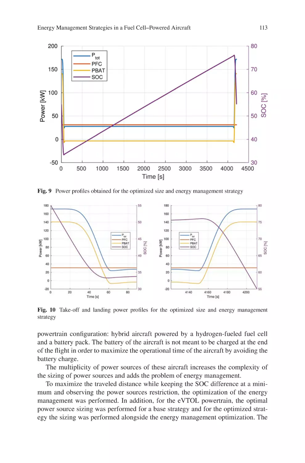
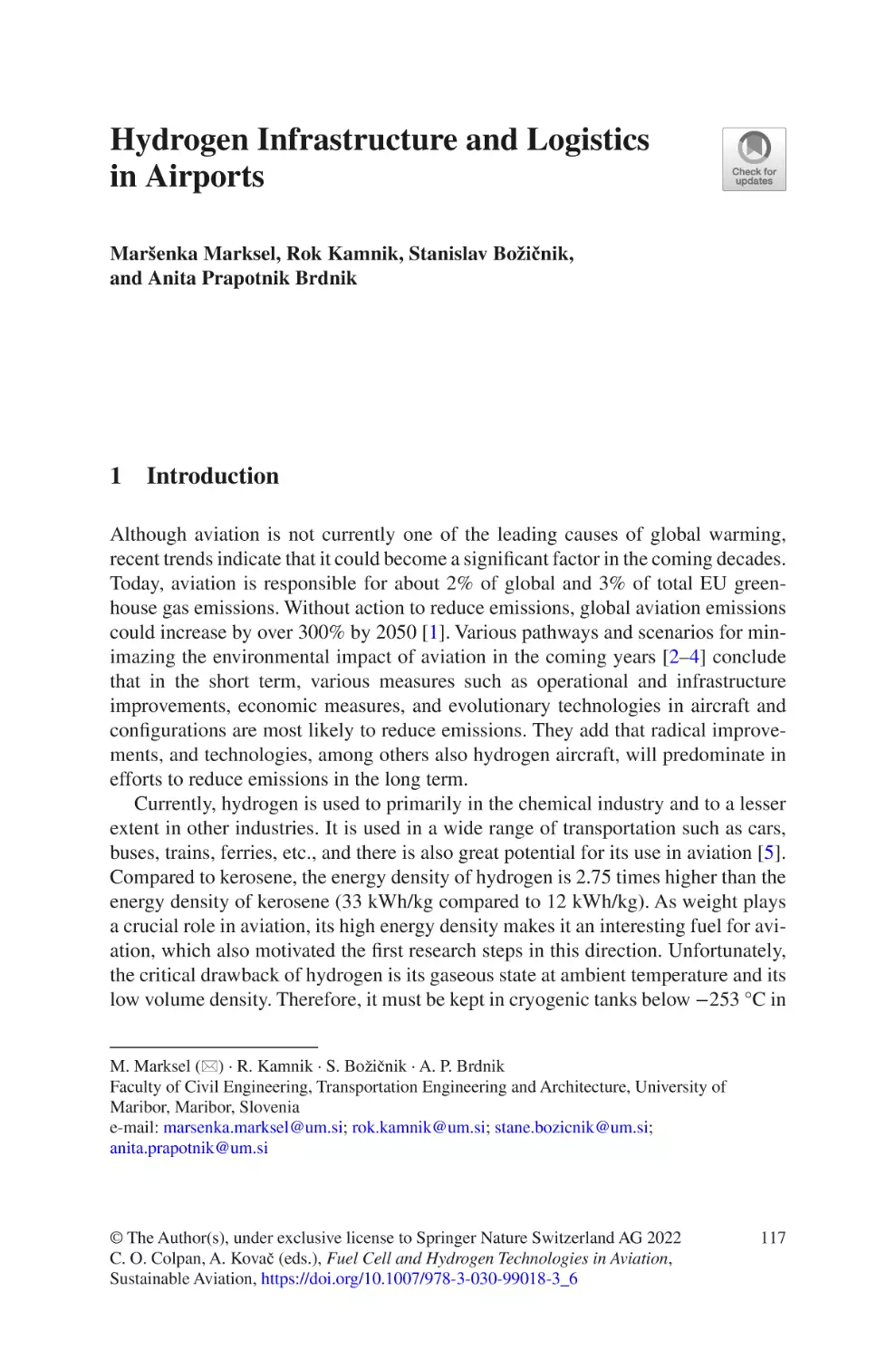
Management Strategies in a Fuel Cell–Powered Aircraft�������������� 97
Pedro Muñoz, Enrico Cestino, and Gabriel Correa
Hydrogen
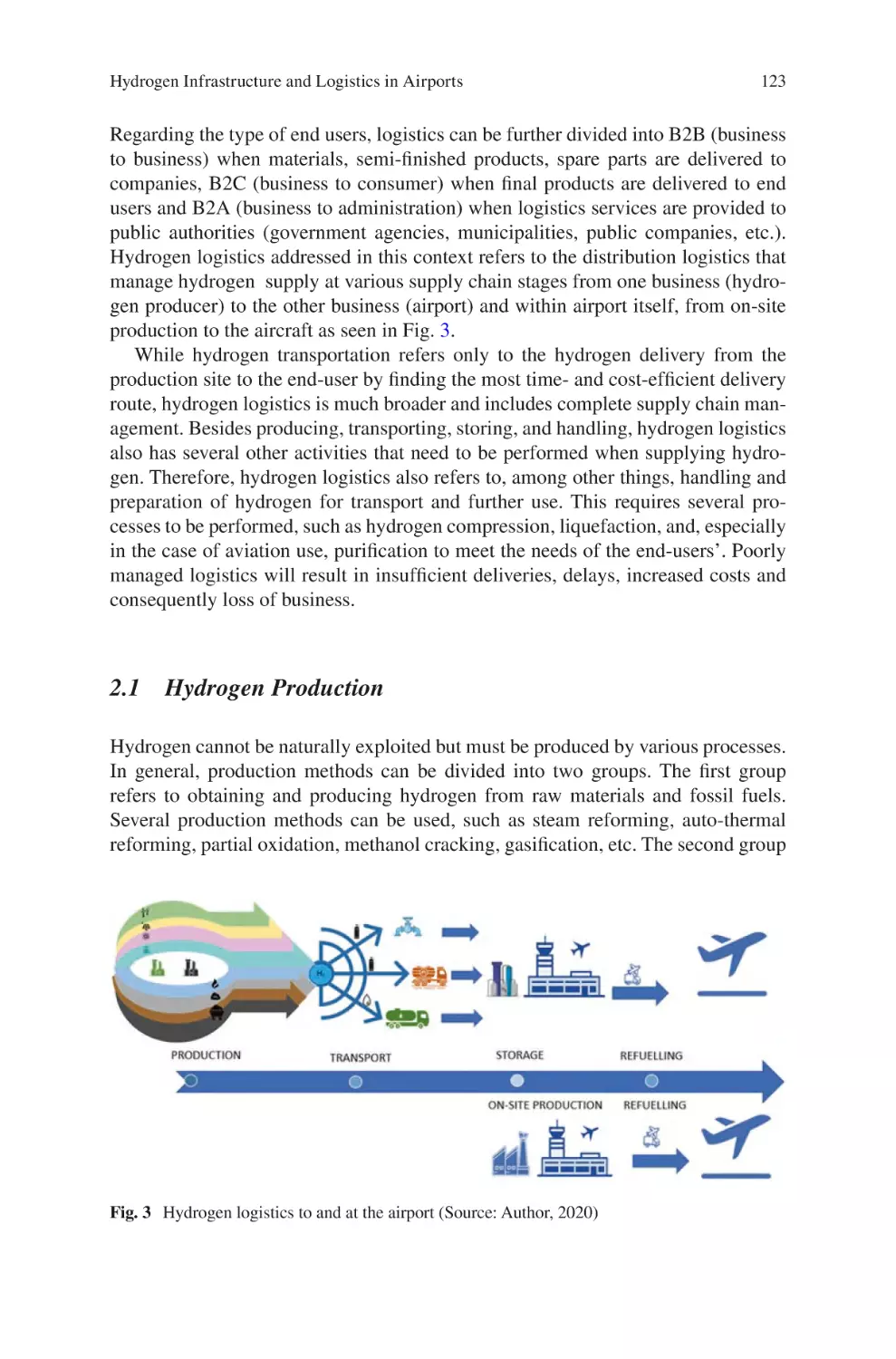
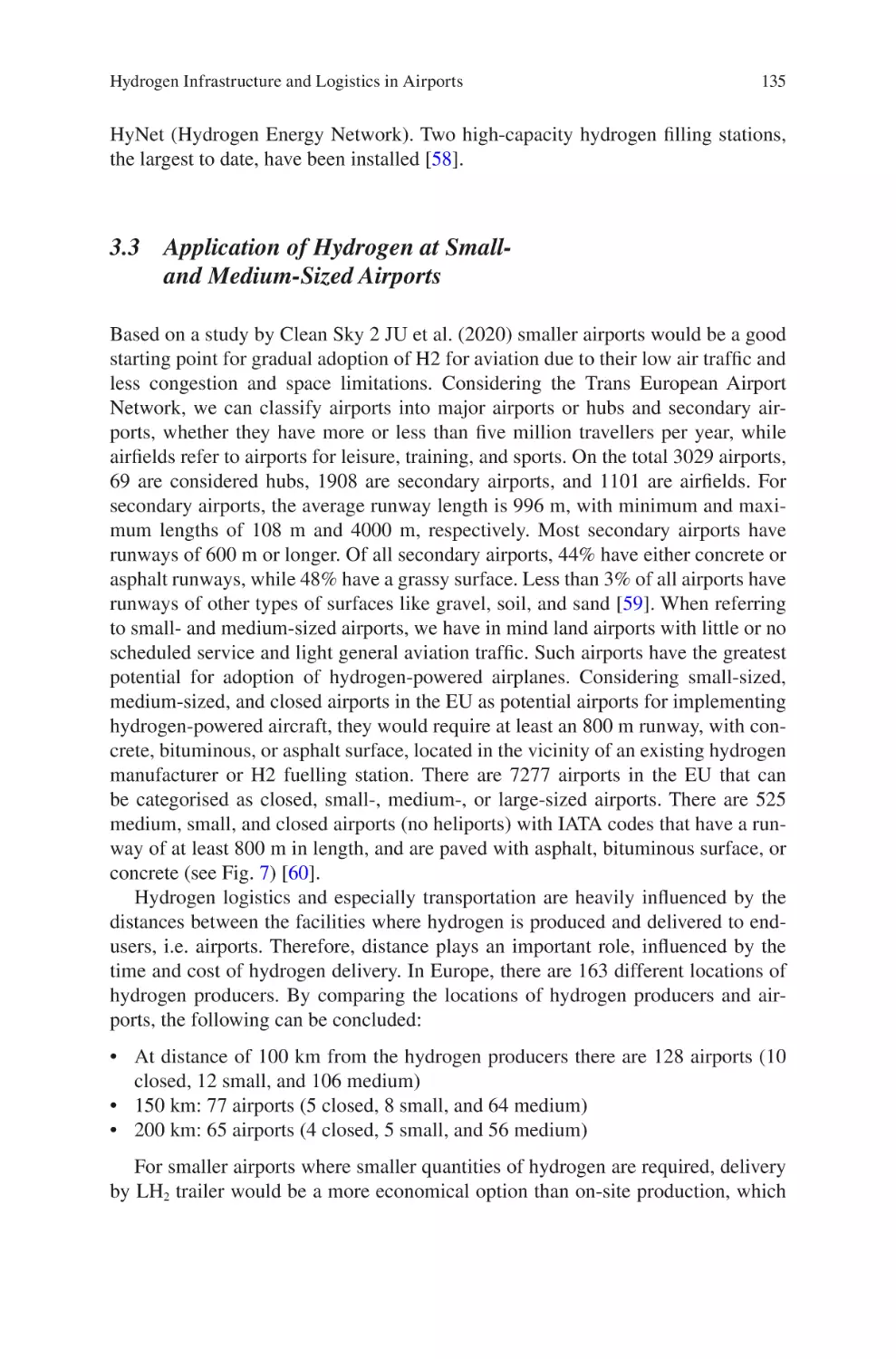
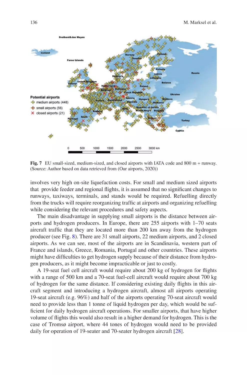
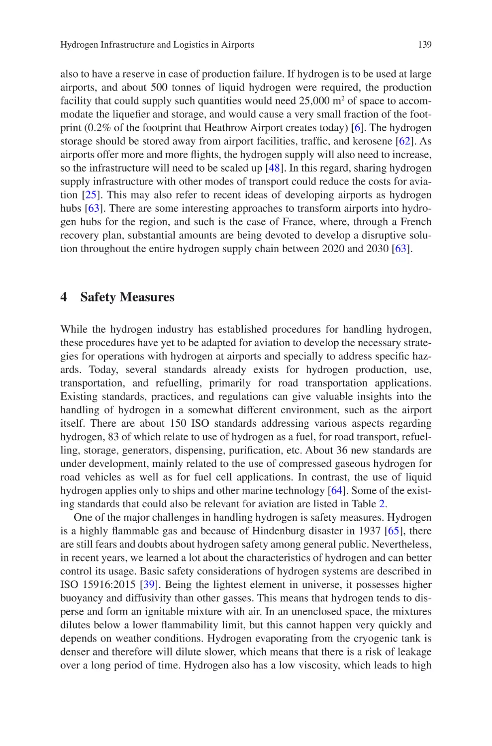
Infrastructure and Logistics in Airports�������������������������������������� 117
Maršenka Marksel, Rok Kamnik, Stanislav Božičnik,
and Anita Prapotnik Brdnik
Fuel
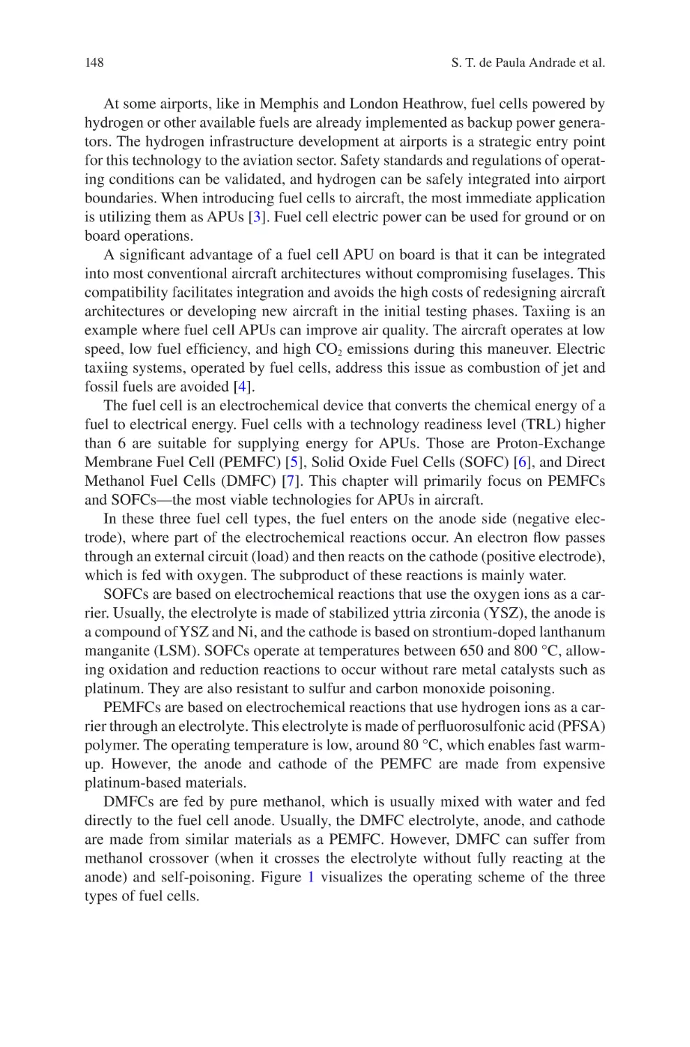
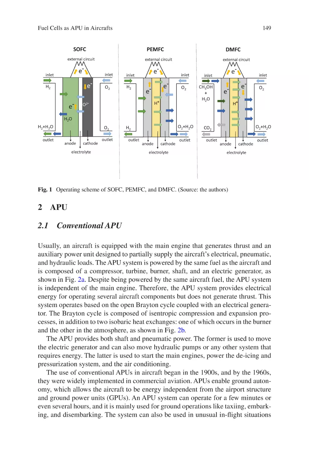
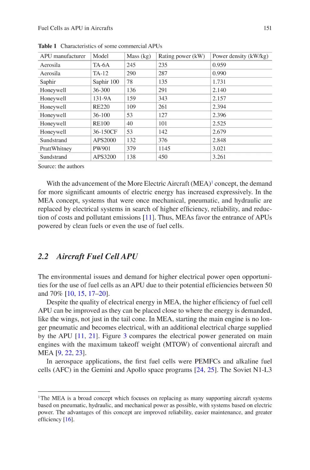
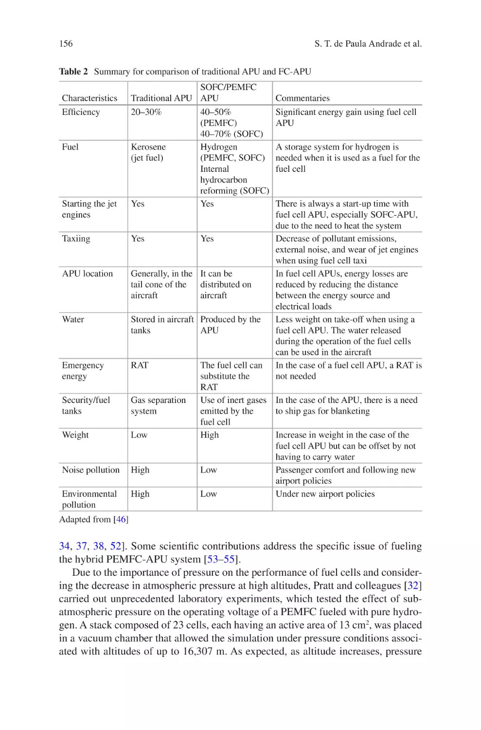
Cells as APU in Aircrafts������������������������������������������������������������������������ 147
Samuel Tadeu de Paula Andrade, Marina Domingues Fernandes,
Victor N. Bistritzki, Rosana Zacarias Domingues, and Tulio Matencio
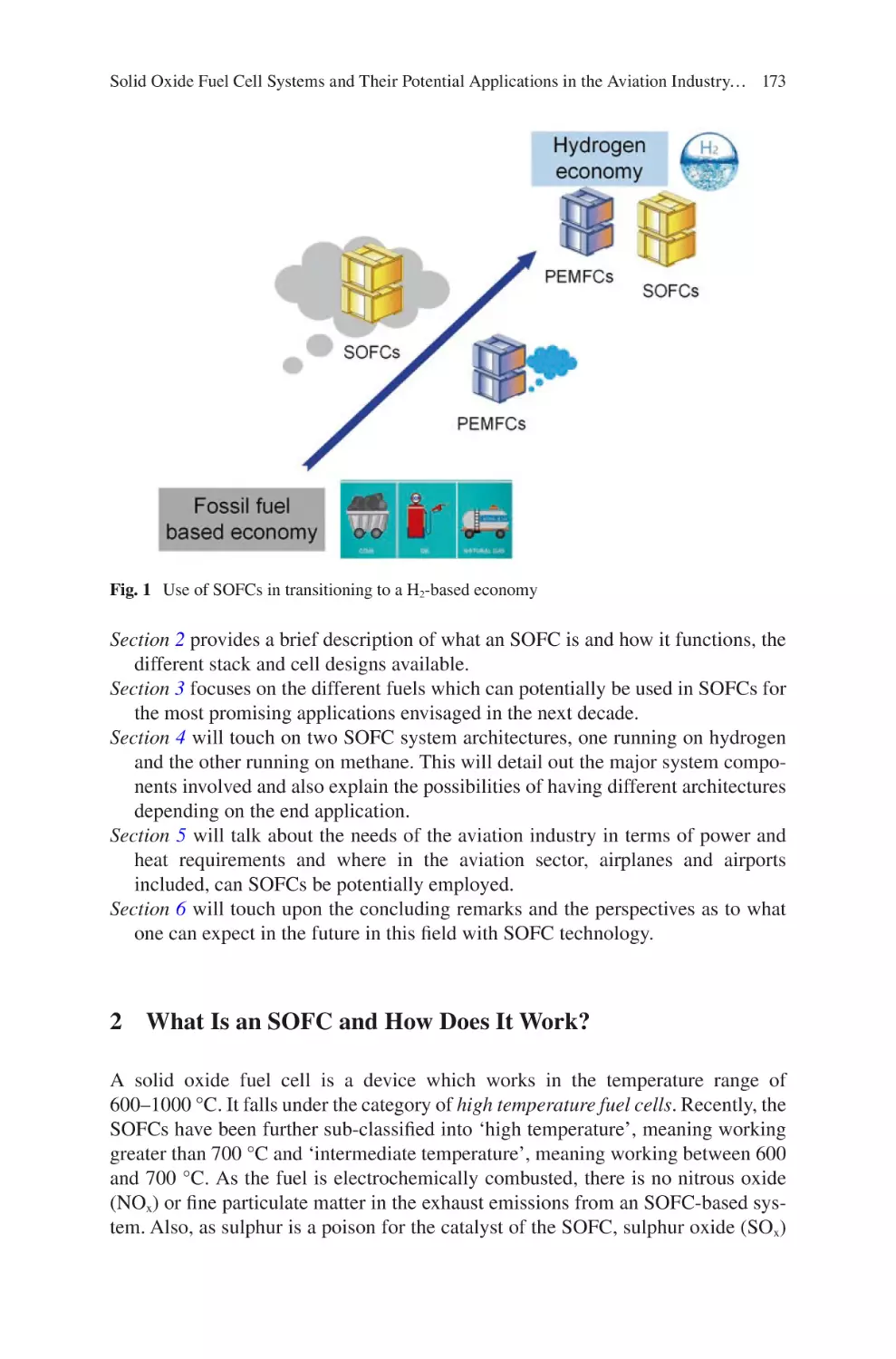
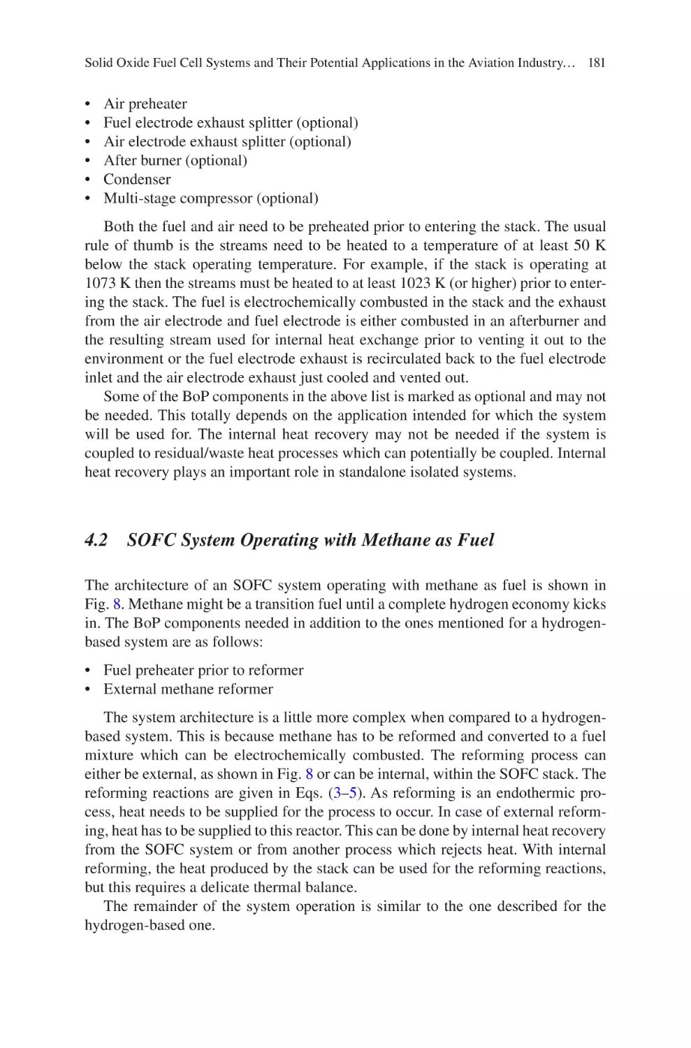
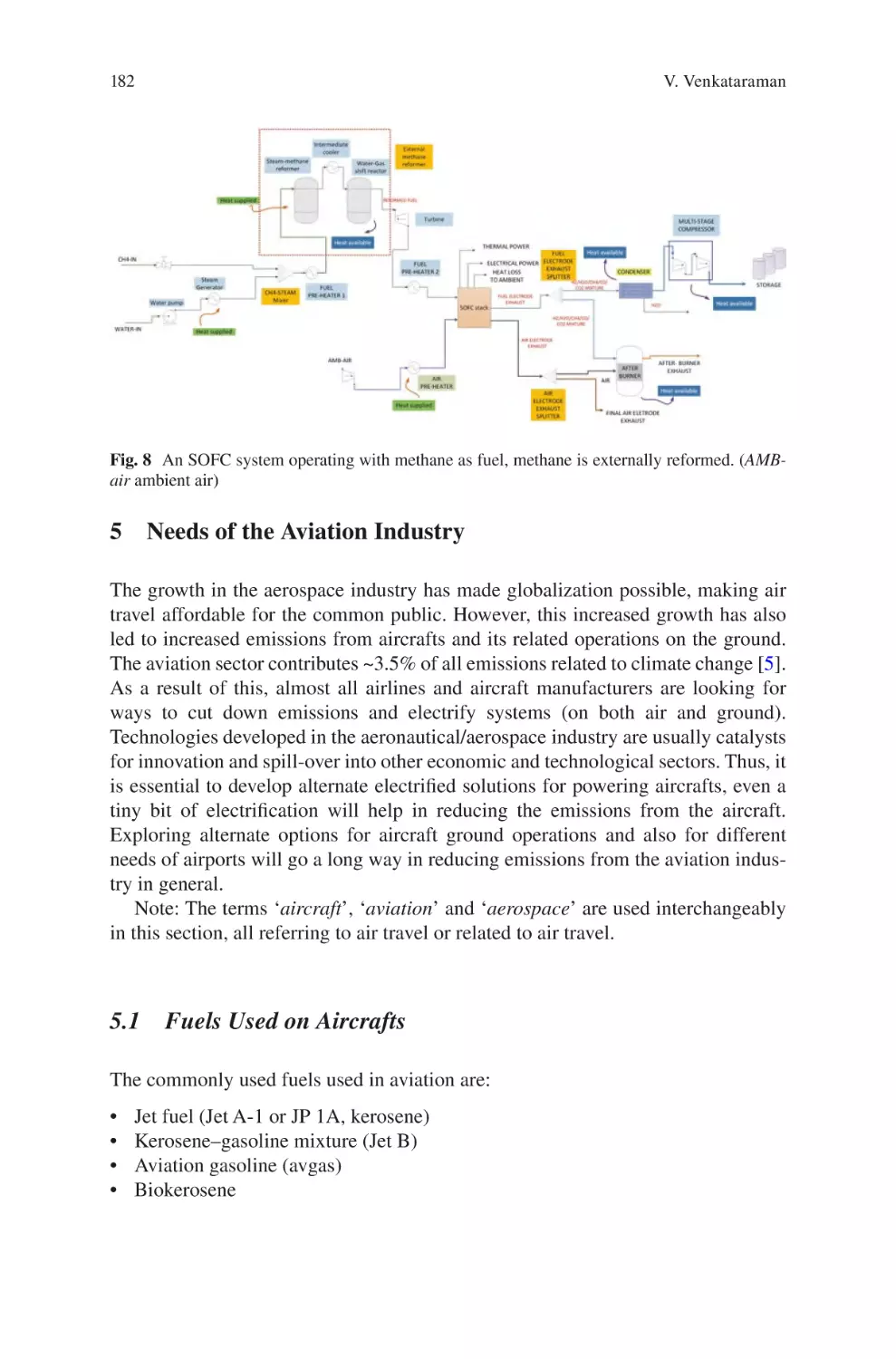
Solid Oxide Fuel Cell Systems and Their Potential Applications
in the Aviation Industry and Beyond�������������������������������������������������������������� 171
Vikrant Venkataraman
Index������������������������������������������������������������������������������������������������������������������ 197
vii
Hydrogen Storage Technology for Aerial
Vehicles
Dirk Kastell
1 Introduction on Hydrogen Storage
The use of hydrogen in aerospace has a long history in the last century, especially
when looking at space applications. Since the early 1930s, hydrogen was extensively used, as it is the only fuel capable to power rockets into earth’s orbit.
Therefore, today, the use of hydrogen as propulsion fuel is in space application still
the standard. Nevertheless, for the civil aviation industry, the use of hydrogen was
always experimental and is still under investigation. Even when the requirements
for space applications are high, they are different of those in aviation. An aircraft
can be in service for over 30 years and will transport in this time thousands of passengers, compared to the one-time use of a space rocket and the limited transport
capabilities. Therefore, hydrogen storages for the aviation industry have to be qualified to the more stringent aviation certification requirements, which include intensive vibration and thermal fatigue testing for the lifetime period. Today, besides the
classical way of gas storage, there are other ways to bunker hydrogen. Especially, in
the last two centuries, many applications have been investigated. The growing popularity to use fuel cells for mobility also pushed this technical interest on these developments. This chapter on hydrogen storage technologies in aviation is intended to
give an overview of the available methods.
D. Kastell (*)
Hamburg, Germany
e-mail: dirk.kastell@gmx.de
© The Author(s), under exclusive license to Springer Nature Switzerland AG 2022
C. O. Colpan, A. Kovač (eds.), Fuel Cell and Hydrogen Technologies in Aviation,
Sustainable Aviation, https://doi.org/10.1007/978-3-030-99018-3_1
1
2
D. Kastell
2 History of Hydrogen Storage
Looking at the limited history of hydrogen aircraft, there are the MARTIN B-57B
in the 1950s and the TUPOLEV TU-155 in the 1970s, setting the standard in their
century. Both were using liquid hydrogen and both were not commercialized due to
technical barriers, but mainly because of the affordable price. Focusing only on
hydrogen storage for flying vehicles, there are older examples, which are the
Zeppelins. They were not flying with hydrogen (they used diesel), but they used
hydrogen as light gas to fly [1]. At this time, helium was expensive and had limited
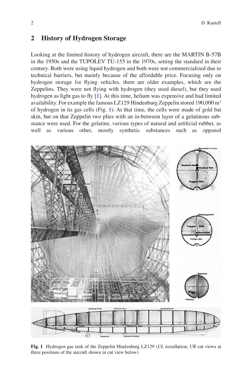
availability. For example the famous LZ129 Hindenburg Zeppelin stored 190,000 m3
of hydrogen in its gas cells (Fig. 1). At that time, the cells were made of gold bat
skin, but on that Zeppelin two plies with an in-between layer of a gelatinous substance were used. For the gelatine, various types of natural and artificial rubber, as
well as various other, mostly synthetic substances such as oppanol
Fig. 1 Hydrogen gas tank of the Zeppelin Hindenburg LZ129 (UL installation, UR cut views at
three positions of the aircraft shown in cut view below)
Hydrogen Storage Technology for Aerial Vehicles
3
(polyisobutylene) were used as sealants. The gas permeability with this technology
was only 1/m2 in 24 h, which is still challenging today, having in mind the free surface of 56,878 m2 and a cell weight of 203 g/m3. At that time, the technology requirements were the same as today; the hydrogen gas tanks had to be lightweight and
tide. Especially because of the permeability of hydrogen as the lightest element and
a gas of diatomic molecules with the formula H2, special care and technologies have
to be used to keep the gas in its storage. A heavy metal storage tank is the easiest
solution, but in commercial aviation, it leads to a decrease of the payload capacity.
Therefore, even today, much research is investigated into the development of lightweight materials like carbon fibre or thermoplastic. Looking at the typical storage
condition at high pressure for gaseous hydrogen or low temperature for liquid
hydrogen, this creates additional technical challenges.
Whereas in the past the use of hydrogen was mainly related to the application of
propulsion or with the intention to have a fast-flying aircraft like a supersonic aircraft, today the use of hydrogen is driven by the idea to decarbonize the aviation
industry. So besides the intention to burn hydrogen in engines, which will lead to
NOx emission, hydrogen can be used with a fuel cell as an alternative electric
energy generation source to fly an aircraft with no emission at all. If hydrogen is
also produced without carbon emission, e.g. generated by sustainable energy (solar,
wind or bio), the propulsion technology is emission free.
3 Hydrogen Storage Technologies
There are many ways to store hydrogen for later use. From the thermodynamic point
of view, it has to be remembered that hydrogen boils at −252.77 °C (20.33 K). The
melting point is at 259.1 °C, and the critical point is at −240 °C at 1 atm. The density is 0.0899 g/l at standard atmosphere. Liquid hydrogen has a specific gravity of
70.99 g/l, which is 790 times the one of gaseous hydrogen. The volume-related
energy density of liquid hydrogen is about 1/4 that of gasoline and about 1/3 that of
natural gas. The weight content of hydrogen in water is 11.2%.
The typical hydrogen is gaseous at standard atmospheric condition, and therefore, it is most times stored in this form at different pressure conditions. Today pressures of 350 bar and 700 bar have been established for different usages. Especially
in the mobility sector, it is often used in this form as it is comparable to other gas
storage systems used in the automotive industry. Nevertheless, there are various
other ways to store hydrogen, e.g. as cryogenic compressed or in liquid condition.
Other ways of hydrogen storage are using different kinds of media like adsorption
material and metal hybrid. Nevertheless, most storages use a vessel. Another way to
store hydrogen is to convert it to a different chemical compound like methane or
ammoniac. These compounds can then be stored and transported very easy, and
hydrogen can be extracted for its final use at the place it is needed. Nevertheless, this
kind of change is not always possible at every place. The uses of the last kind of
storage conditions are usable for many industries. However, having aviation in
4
D. Kastell
mind, because of the additional safety risks going along with the regeneration of
hydrogen, today only the physical storage of hydrogen in a vessel is in the focus of
the development in the aviation industry.
Specifying different types of hydrogen storage, there are six types of conservation. All storage methods have their advantages and disadvantages, each of which
qualifies them for different tasks. In practice, there are also mixtures of different
types used:
•
•
•
•
•
•
•
Compressed gaseous hydrogen
Cryogenic compressed hydrogen
Cryogenic liquid hydrogen
Metal hybrid hydrogen storage
Chemical hydrogen storage
Organic hydrogen storage
Adsorption hydrogen storage
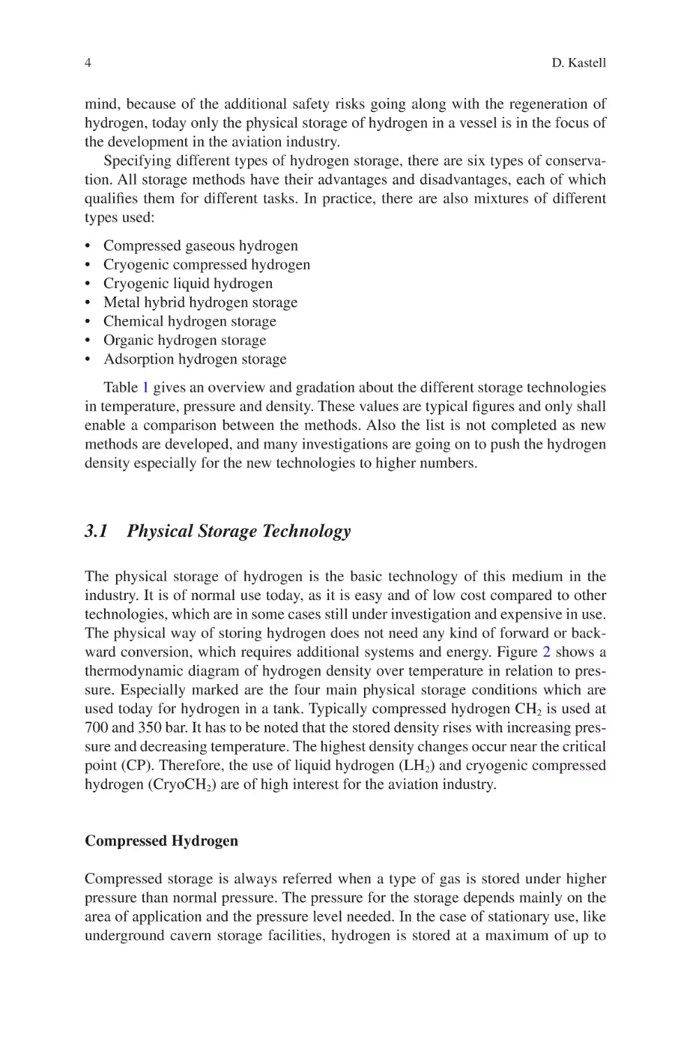
Table 1 gives an overview and gradation about the different storage technologies
in temperature, pressure and density. These values are typical figures and only shall
enable a comparison between the methods. Also the list is not completed as new
methods are developed, and many investigations are going on to push the hydrogen
density especially for the new technologies to higher numbers.
3.1 Physical Storage Technology
The physical storage of hydrogen is the basic technology of this medium in the
industry. It is of normal use today, as it is easy and of low cost compared to other
technologies, which are in some cases still under investigation and expensive in use.
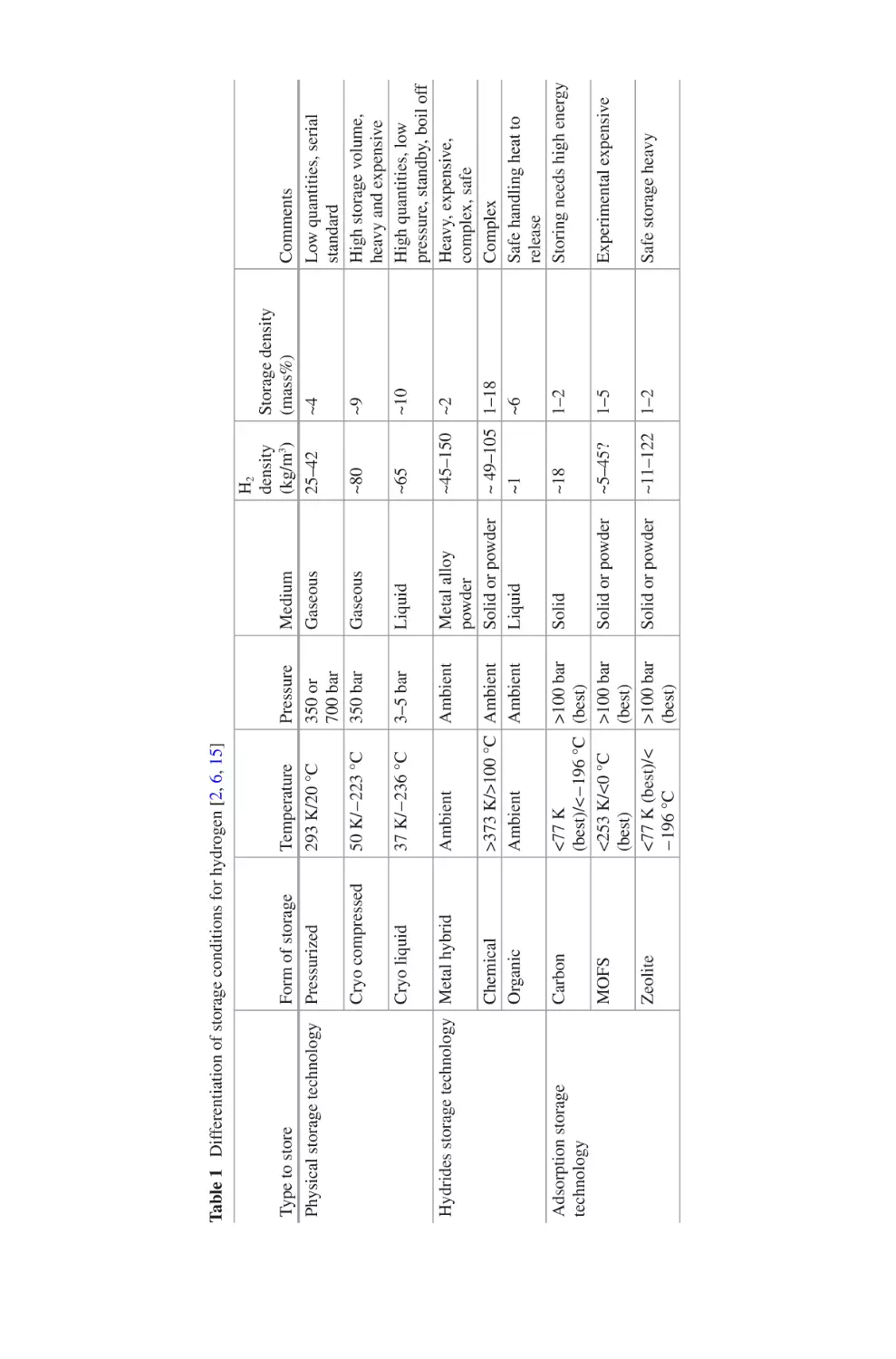
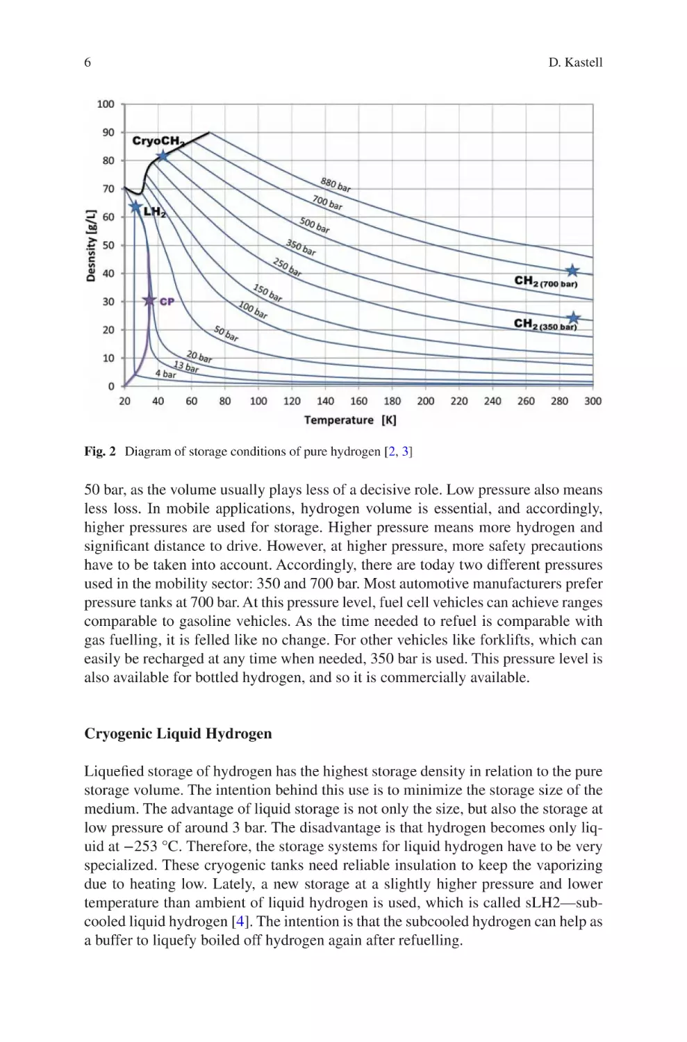
The physical way of storing hydrogen does not need any kind of forward or backward conversion, which requires additional systems and energy. Figure 2 shows a
thermodynamic diagram of hydrogen density over temperature in relation to pressure. Especially marked are the four main physical storage conditions which are
used today for hydrogen in a tank. Typically compressed hydrogen CH2 is used at
700 and 350 bar. It has to be noted that the stored density rises with increasing pressure and decreasing temperature. The highest density changes occur near the critical
point (CP). Therefore, the use of liquid hydrogen (LH2) and cryogenic compressed
hydrogen (CryoCH2) are of high interest for the aviation industry.
Compressed Hydrogen
Compressed storage is always referred when a type of gas is stored under higher
pressure than normal pressure. The pressure for the storage depends mainly on the
area of application and the pressure level needed. In the case of stationary use, like
underground cavern storage facilities, hydrogen is stored at a maximum of up to
50 K/−223 °C
37 K/−236 °C
Cryo compressed
Cryo liquid
Adsorption storage
technology
Zeolite
MOFS
Carbon
Chemical
Organic
Ambient
3–5 bar
Pressure
350 or
700 bar
350 bar
<77 K
(best)/<−196 °C
<253 K/<0 °C
(best)
<77 K (best)/<
−196 °C
>100 bar
(best)
>100 bar
(best)
>100 bar
(best)
>373 K/>100 °C Ambient
Ambient
Ambient
Ambient
Temperature
293 K/20 °C
Form of storage
Pressurized
Hydrides storage technology Metal hybrid
Type to store
Physical storage technology
Table 1 Differentiation of storage conditions for hydrogen [2, 6, 15]
Solid or powder
Solid or powder
Solid
Metal alloy
powder
Solid or powder
Liquid
Liquid
Gaseous
Medium
Gaseous
~2
~10
~9
Storage density
(mass%)
~4
~11–122
~5–45?
~18
1–2
1–5
1–2
~ 49–105 1–18
~1
~6
~45–150
~65
~80
H2
density
(kg/m3)
25–42
Safe storage heavy
Experimental expensive
Comments
Low quantities, serial
standard
High storage volume,
heavy and expensive
High quantities, low
pressure, standby, boil off
Heavy, expensive,
complex, safe
Complex
Safe handling heat to
release
Storing needs high energy
6
D. Kastell
Fig. 2 Diagram of storage conditions of pure hydrogen [2, 3]
50 bar, as the volume usually plays less of a decisive role. Low pressure also means
less loss. In mobile applications, hydrogen volume is essential, and accordingly,
higher pressures are used for storage. Higher pressure means more hydrogen and
significant distance to drive. However, at higher pressure, more safety precautions
have to be taken into account. Accordingly, there are today two different pressures
used in the mobility sector: 350 and 700 bar. Most automotive manufacturers prefer
pressure tanks at 700 bar. At this pressure level, fuel cell vehicles can achieve ranges
comparable to gasoline vehicles. As the time needed to refuel is comparable with
gas fuelling, it is felled like no change. For other vehicles like forklifts, which can
easily be recharged at any time when needed, 350 bar is used. This pressure level is
also available for bottled hydrogen, and so it is commercially available.
Cryogenic Liquid Hydrogen
Liquefied storage of hydrogen has the highest storage density in relation to the pure
storage volume. The intention behind this use is to minimize the storage size of the
medium. The advantage of liquid storage is not only the size, but also the storage at
low pressure of around 3 bar. The disadvantage is that hydrogen becomes only liquid at −253 °C. Therefore, the storage systems for liquid hydrogen have to be very
specialized. These cryogenic tanks need reliable insulation to keep the vaporizing
due to heating low. Lately, a new storage at a slightly higher pressure and lower
temperature than ambient of liquid hydrogen is used, which is called sLH2—subcooled liquid hydrogen [4]. The intention is that the subcooled hydrogen can help as
a buffer to liquefy boiled off hydrogen again after refuelling.
Hydrogen Storage Technology for Aerial Vehicles
7
Compared to the standard kerosene used in aviation, hydrogen has only a third of
the energy of this medium. Today, the use of liquid hydrogen is anticipated by the
aviation industry to overcome the usage of large vessels in the aircraft which badly
influence the aerodynamic or the payload of the aircraft. That is why liquid hydrogen is also used for centuries as rocket fuel in space travel. Liquid cryogenic hydrogen is also used for storage on ground for delivery by truck for reasons of space. It
can then be evaporated into gaseous hydrogen at the filling station. In practice, liquid hydrogen usage has disadvantages compared to the pressure variant. For example, evaporation losses cannot be completely avoided during longer service lives of
vehicles. Moreover, the energy required to provide liquid hydrogen is higher than
for pressurized hydrogen. Today also, the industrial capacity to produce liquid
hydrogen is not high and will be one of the challenges in the future for the usage of
this medium.
Cryogenic Compressed Hydrogen Style
Cryogenic compressed hydrogen storage refers to the storage of hydrogen at cryogenic temperatures in a pressurized vessel (nominally at 350 bar), in contrast to
current cryogenic vessels that store liquid hydrogen at near-ambient pressures.
Cryogenic compressed hydrogen storage can include liquid hydrogen, cold compressed hydrogen, or hydrogen in a two-phase region (saturated liquid and vapour).
With cryogenic compressed hydrogen even higher densities than with liquid hydrogen can be reached [3]. But this condition goes along with the design requirements
not only to have a good insulation of the vessel but also to apply the precaution for
a high-pressure accumulator, which means in most cases thicker walls and higher
weight. So where on the one side, the cryo-compressed storage system has the
potential to meet the needed volumetric capacity in the automotive industry, it has a
high-volume manufacturing cost [5]. But especially the weight is a drawback for the
aviation industry and is therefore not considered for usage [18].
3.2 Hydrides Storage Technology
One other different way of storing hydrogen is the use of chemical hydrides, which
means hydrogen is stored as a combination of another chemical element. This binding is not fixed and can be released at any time, when a special treatment, e.g. heat
or pressure, is applied. In some cases, even this is not required. The overview below
gives the formula of most hydrogen chemical compounds with their state at standard atmosphere. Many of the chemical hydrides used today in research are using
those combinations as a baseline. This application is a wide open field of experimental examinations, which are still going on today. Prior to the 2003 timeframe,
most material-based hydrogen storage technology development had focused on
reversible interstitial metal hydrides. Nevertheless, some elements have already left
the experimental stage. In Fig. 3, the stored hydrogen mass for different elements is
8
D. Kastell
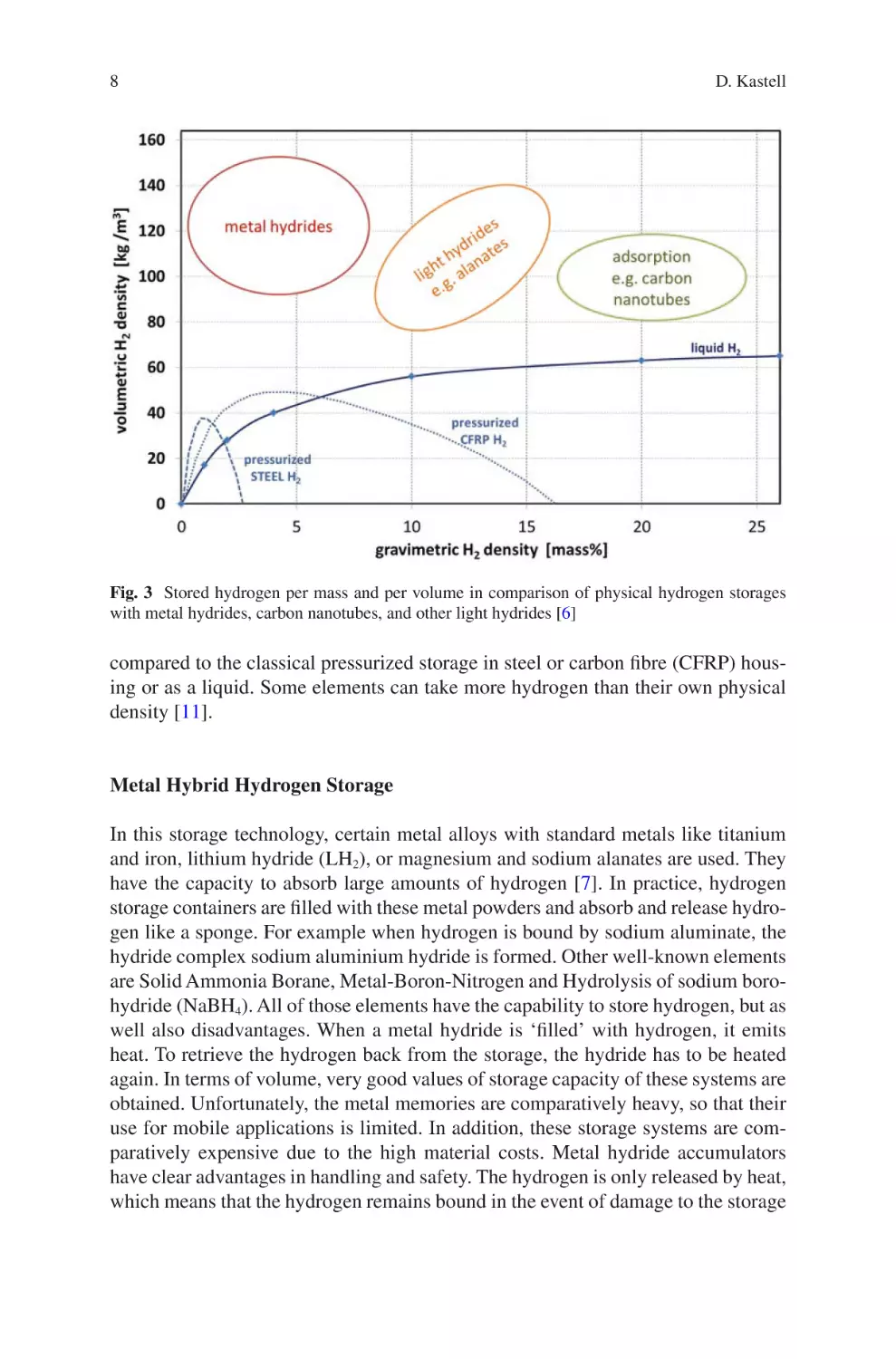
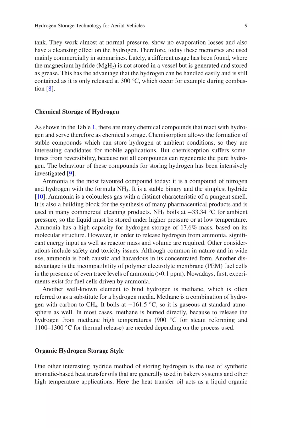
Fig. 3 Stored hydrogen per mass and per volume in comparison of physical hydrogen storages
with metal hydrides, carbon nanotubes, and other light hydrides [6]
compared to the classical pressurized storage in steel or carbon fibre (CFRP) housing or as a liquid. Some elements can take more hydrogen than their own physical
density [11].
Metal Hybrid Hydrogen Storage
In this storage technology, certain metal alloys with standard metals like titanium
and iron, lithium hydride (LH2), or magnesium and sodium alanates are used. They
have the capacity to absorb large amounts of hydrogen [7]. In practice, hydrogen
storage containers are filled with these metal powders and absorb and release hydrogen like a sponge. For example when hydrogen is bound by sodium aluminate, the
hydride complex sodium aluminium hydride is formed. Other well-known elements
are Solid Ammonia Borane, Metal-Boron-Nitrogen and Hydrolysis of sodium borohydride (NaBH4). All of those elements have the capability to store hydrogen, but as
well also disadvantages. When a metal hydride is ‘filled’ with hydrogen, it emits
heat. To retrieve the hydrogen back from the storage, the hydride has to be heated
again. In terms of volume, very good values of storage capacity of these systems are
obtained. Unfortunately, the metal memories are comparatively heavy, so that their
use for mobile applications is limited. In addition, these storage systems are comparatively expensive due to the high material costs. Metal hydride accumulators
have clear advantages in handling and safety. The hydrogen is only released by heat,
which means that the hydrogen remains bound in the event of damage to the storage
Hydrogen Storage Technology for Aerial Vehicles
9
tank. They work almost at normal pressure, show no evaporation losses and also
have a cleansing effect on the hydrogen. Therefore, today these memories are used
mainly commercially in submarines. Lately, a different usage has been found, where
the magnesium hydride (MgH2) is not stored in a vessel but is generated and stored
as grease. This has the advantage that the hydrogen can be handled easily and is still
contained as it is only released at 300 °C, which occur for example during combustion [8].
Chemical Storage of Hydrogen
As shown in the Table 1, there are many chemical compounds that react with hydrogen and serve therefore as chemical storage. Chemisorption allows the formation of
stable compounds which can store hydrogen at ambient conditions, so they are
interesting candidates for mobile applications. But chemisorption suffers sometimes from reversibility, because not all compounds can regenerate the pure hydrogen. The behaviour of these compounds for storing hydrogen has been intensively
investigated [9].
Ammonia is the most favoured compound today; it is a compound of nitrogen
and hydrogen with the formula NH3. It is a stable binary and the simplest hydride
[10]. Ammonia is a colourless gas with a distinct characteristic of a pungent smell.
It is also a building block for the synthesis of many pharmaceutical products and is
used in many commercial cleaning products. NH3 boils at −33.34 °C for ambient
pressure, so the liquid must be stored under higher pressure or at low temperature.
Ammonia has a high capacity for hydrogen storage of 17.6% mass, based on its
molecular structure. However, in order to release hydrogen from ammonia, significant energy input as well as reactor mass and volume are required. Other considerations include safety and toxicity issues. Although common in nature and in wide
use, ammonia is both caustic and hazardous in its concentrated form. Another disadvantage is the incompatibility of polymer electrolyte membrane (PEM) fuel cells
in the presence of even trace levels of ammonia (>0.1 ppm). Nowadays, first, experiments exist for fuel cells driven by ammonia.
Another well-known element to bind hydrogen is methane, which is often
referred to as a substitute for a hydrogen media. Methane is a combination of hydrogen with carbon to CH4. It boils at −161.5 °C, so it is gaseous at standard atmosphere as well. In most cases, methane is burned directly, because to release the
hydrogen from methane high temperatures (900 °C for steam reforming and
1100–1300 °C for thermal release) are needed depending on the process used.
Organic Hydrogen Storage Style
One other interesting hydride method of storing hydrogen is the use of synthetic
aromatic-based heat transfer oils that are generally used in bakery systems and other
high temperature applications. Here the heat transfer oil acts as a liquid organic
10
D. Kastell
hydrogen carrier (LOHC). LOHCs are organic compounds that can absorb and
release hydrogen through chemical reactions. LOHCs can therefore be used as storage media for hydrogen. The hydrogen is stored inside the liquid hydrogen carriers
via a catalytic reaction. The liquid now has a low viscosity and looks like water.
After the hydrogenation by the temperature of around 300 °C, the viscosity increases
again and the liquid looks like honey.
Since the (optimal) LOHC is liquid at ambient conditions and shows similar
properties as crude oil based liquids (e.g. diesel, gasoline), it can easily be handled,
transported and stored. When loaded with hydrogen, LOHC is flame-retardant,
which makes it a safe transport medium for hydrogen to the location of use where
the hydrogen can be unloaded from this carrier liquid. Today, the most promising
LOHC candidates are dibenzyltoluene for energy-transport and energy-storage as
well as N-Ethyl-Carbazole for mobility applications [11].
3.3 Adsorption Storage Technology
Carbon Hydrogen Storage
One other way of storing hydrogen is a similar use like the metallic hybrid solution. In
this case, materials with a large inner surface area and suitable pore size, which prefers
to attach certain gases, are used. Porous carbon is a long-known material with those
suitable properties [12]. This carbon is a synthetic carbon modification containing very
small graphite crystallites and amorphous carbon. The operational dynamics can be
over a wide pressure and temperature range, but it requires complex storage management. There is a thermal method with a treatment at 700–1000 °C in the presence of
oxidizing gases such as CO2 steam or air and the chemical method with a treatment at
500–800 °C in the presence of dehydrating chemical substance. All of these treatments
are only rudimentary developed today. Typically the carbon is produced in nanotubes
or nanofibers, which are used to fill up a storage vessel. The reversible hydrogen sorption process is based on physisorption, and the amount of adsorbed hydrogen is proportional to the surface area of the nanostructured carbon. Typically a storage of lower
than 1% mass can be achieved, but when the storage condition is changed to low temperature 77 K and high pressure >100 bar higher storage density of at least 2% mass is
achieved [13]. Nevertheless, this storage condition is again leading to higher efforts for
the storage vessel similar to the one for cryogenic compressed hydrogen.
Hydrogen Storage in Zeolite
Zeolites are also well-known storage materials. They can be of natural and synthetic
origin and are crystalline aluminosilicate compounds with a cavity- and channel-
type pore structures, used to store the hydrogen. Their pore structure offers a high
internal surface area, nevertheless at ambient condition only a hydrogen uptake of
<1% mass is reached [13]. To improve the storage mass of hydrogen like for carbon,
Hydrogen Storage Technology for Aerial Vehicles
11
the pressure and temperature have to be raised to higher values. At the same time,
also different substitutions like lithium borohydride LiBH4, used also as metal
hydride, can be used to improve the storing capacity [14].
Nevertheless zeolites will probably never be considered as an ideal storage
medium for hydrogen in mobile application, as they are all relatively heavy compared to carbon or MOFs (where carbon, nitrogen and oxygen make the bulk of the
structure). But they have potential as a cheap bulk stationary storage, because of
their thermal and chemical stability to store hydrogen safely.
MOFs as Hydrogen Storage
The last named storage material is the so-called metal organic frameworks (MOFs).
They are a new class of materials, named coordination polymers, which are synthesized to allow an influence on the internal surface and porosity. Coordination polymers reach internal surfaces of well over 3000 m2/g. Therefore, a potential for gas
storage, in particular carbon dioxide, methane or hydrogen, is attributed to them and
partly observed. At ambient conditions, storage of 2.5% mass could be achieved.
Therefore, the chemical tuning of the MOFs is investigated to improve the binding
capacity of hydrogen [15]. Also for that material, the use of cryogenic temperatures
and pressures of up to 90 bar can lead to a reversible hydrogen storage capacity of
around 10% mass. To date, however, there is no functioning storage system made of
these materials that would have storage properties better than active porous carbon.
4 Design of Hydrogen Storages
The design of hydrogen storages always depends on the storage technology chosen.
Nevertheless, in most cases, a metal case is used, because when storing pure hydrogen, the containment of the medium in respect of the permeability of the medium
has always to be taken into account. In the case of chemical or adsorption storage
the used components have to be contained in a vessel, whereas some of them like
ammonia are even hazardous. Because of the experimental status with almost all
alternative storage technologies and the risks going along with this, the use of physical hydrogen storage systems are the main focus of the commercial aviation industry. It has to be noted, that in some special cases like unmanned flight vehicles (e.g.
drones) the advantages could be higher than the risk to go over to alternative technologies. Nevertheless, the following chapters will only address the physical storage technologies for commercial aviation.
When designing hydrogen storages, the following points have to be taken into
account:
• System level architecture
• Storage control, monitoring and indication
• Hydrogen storage design and installation
12
D. Kastell
• Tank venting and operation management
• Redundancy and failure mode reconfiguration
4.1 System-Level Architecture
Pressure vessels are organized in five different types which are related to the material and design used:
• Type I: All-metal construction, generally steel.
• Type II: Mainly metal with some fibre overwrap in the hoop direction, mostly
steel or aluminium with a glass fibre composite; the metal vessel and composite
materials share equal structural loading.
• Type III: Metal liner with a full composite overwrap, generally aluminium, with
a carbon fibre composite; the composite materials carry the structural loads, the
liner is for the tightness.
• Type IV: An all-composite construction, polymer (typically high-density polyethylene) liner with carbon fibre or hybrid carbon/glass fibre composite.
• Type V: Liner less, all-composite construction.
Hydrogen tanks for storing liquid hydrogen in aerospace are in many cases made
of metal. For space applications, this solution is still in use, because of non-reuse and
costs. But for commercial aviation, the focus is on the design of a LH2 storage system
made of light carbon fibre-reinforced materials. Using these components, a significantly improved gravimetric index for the whole storage system can be achieved.
The drawback of using these materials is that the laminate quality or laminate architecture is of particular importance for the permeability. Different test specimens,
different semi-finished products made of glass, carbon, fibres with polymer or metal
matrix, different additives, liners and architectures as well as coatings have to be
considered. In addition, a selection of adhesives has to be made for use in cryogenic
environments. Modern pressure accumulators are made of composite materials (thin
inner tanks made of aluminium or polyethylene, reinforced with carbon or glass fibre
on the outside). These constructions are much lighter than steel vessels [27].
For the aviation industry, the storage vessels and associated components must
withstand defined normal static and failure fatigue load cases as well as the demanding environmental (including shock and vibration) and reliability requirements
associated with commercial aviation procedure defined in DO160, DO178 and
DO254 [16]. At the same time, the hydrogen storage design and its installation must
account for thermal deformation as well as pressure and temperature fluctuations
during operation and filling at delta temperatures of ~300 K, when using liquid
hydrogen. For most applications, a metal tank gives the best results for the lowest
price. Especially in the case of physical storage of compressed hydrogen of up to
700 bar, the storage has to have the form of a pressure tank. When simply operating
the vessel, already the thermal expansion of hydrogen leads to higher pressures.
Those pressure storages have therefore to be qualified to factors of the design
Hydrogen Storage Technology for Aerial Vehicles
13
pressure. For the commercial aviation industry, this is regulated by the EASA regulations (CS25 or CS23) [17].
For a high pressure accumulator, the EASA certification regulation (CS25.1435)
requests a proof pressure test of three times the design operating pressure and four
times for the ultimate pressure. These are the values at which the vessel can deform,
but is not allowed to burst. This means that a 700 bar hydrogen accumulator has to
be qualified for 2.800 bars in a large commercial aircraft. It is understandable that
this design requirement leads to a very heavy unit. On the other side, the design of
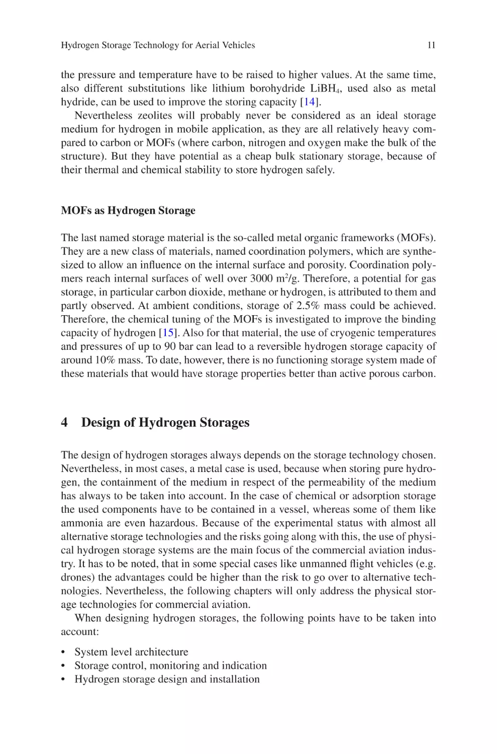
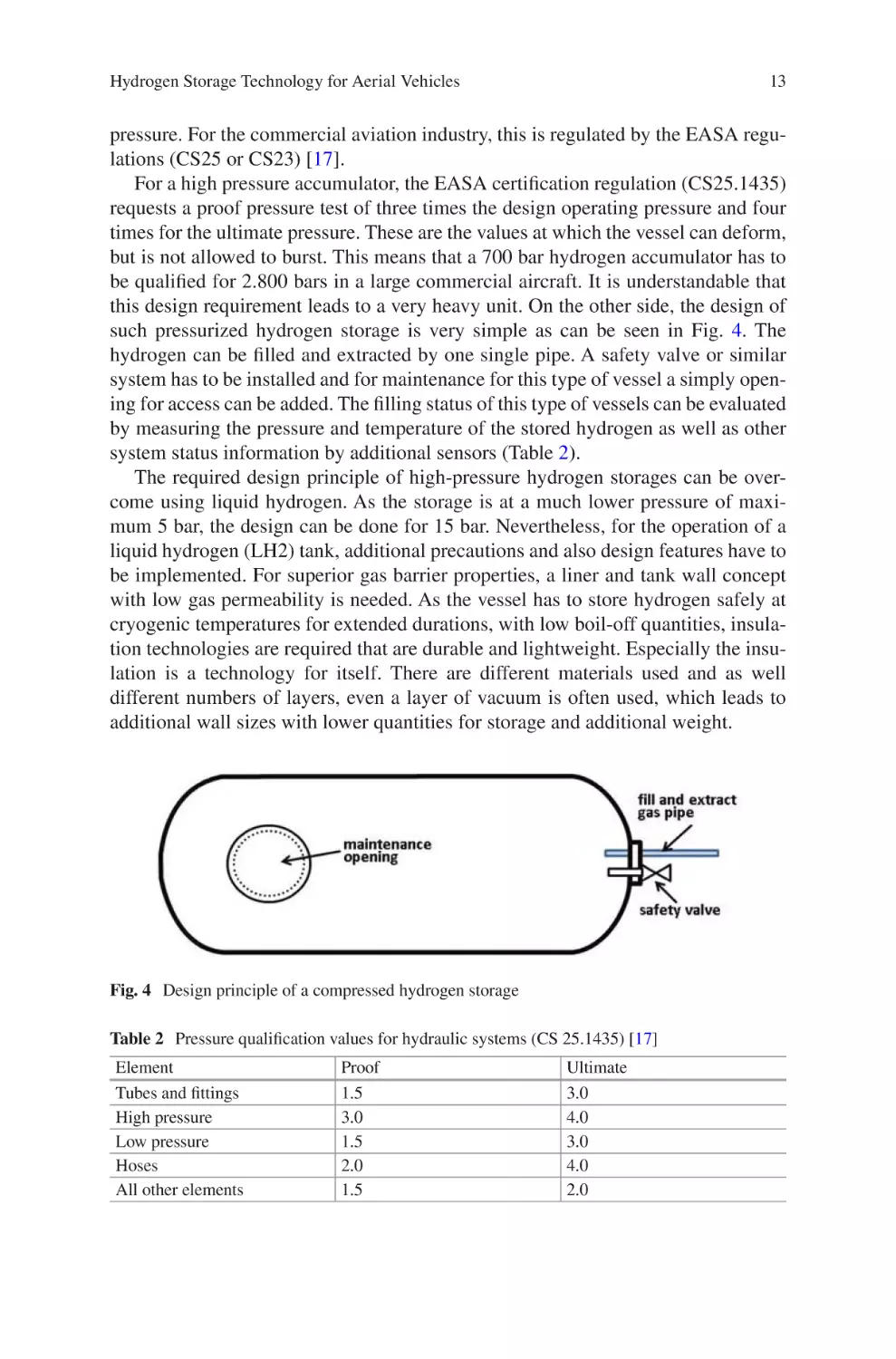
such pressurized hydrogen storage is very simple as can be seen in Fig. 4. The
hydrogen can be filled and extracted by one single pipe. A safety valve or similar
system has to be installed and for maintenance for this type of vessel a simply opening for access can be added. The filling status of this type of vessels can be evaluated
by measuring the pressure and temperature of the stored hydrogen as well as other
system status information by additional sensors (Table 2).
The required design principle of high-pressure hydrogen storages can be overcome using liquid hydrogen. As the storage is at a much lower pressure of maximum 5 bar, the design can be done for 15 bar. Nevertheless, for the operation of a
liquid hydrogen (LH2) tank, additional precautions and also design features have to
be implemented. For superior gas barrier properties, a liner and tank wall concept
with low gas permeability is needed. As the vessel has to store hydrogen safely at
cryogenic temperatures for extended durations, with low boil-off quantities, insulation technologies are required that are durable and lightweight. Especially the insulation is a technology for itself. There are different materials used and as well
different numbers of layers, even a layer of vacuum is often used, which leads to
additional wall sizes with lower quantities for storage and additional weight.
Fig. 4 Design principle of a compressed hydrogen storage
Table 2 Pressure qualification values for hydraulic systems (CS 25.1435) [17]
Element
Tubes and fittings
High pressure
Low pressure
Hoses
All other elements
Proof
1.5
3.0
1.5
2.0
1.5
Ultimate
3.0
4.0
3.0
4.0
2.0
14
D. Kastell
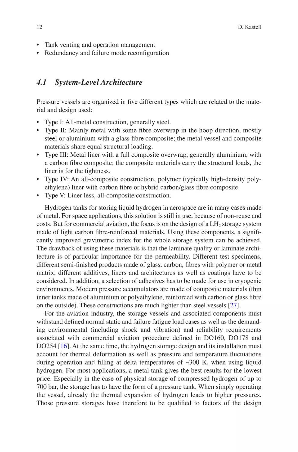
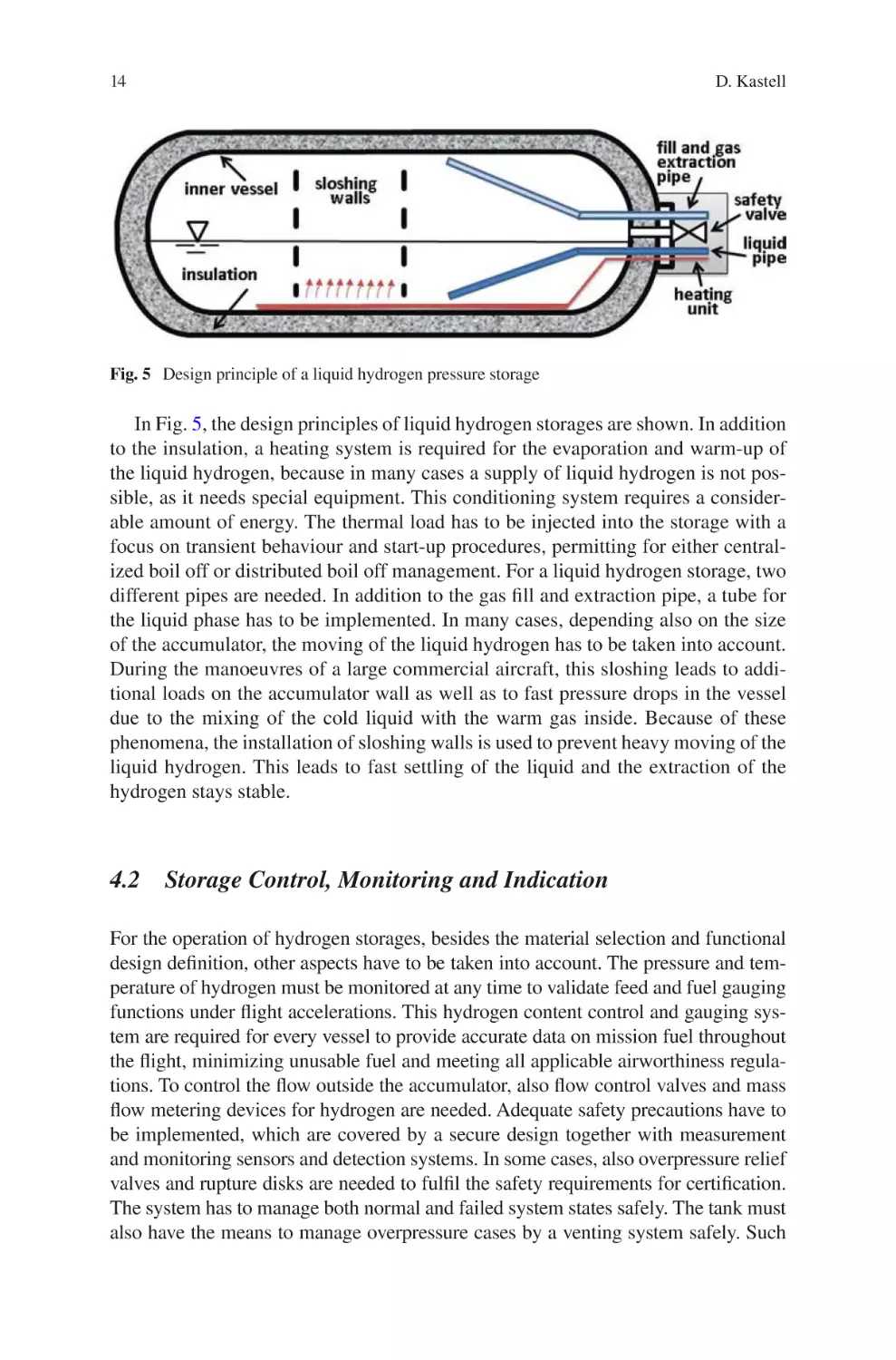
Fig. 5 Design principle of a liquid hydrogen pressure storage
In Fig. 5, the design principles of liquid hydrogen storages are shown. In addition
to the insulation, a heating system is required for the evaporation and warm-up of
the liquid hydrogen, because in many cases a supply of liquid hydrogen is not possible, as it needs special equipment. This conditioning system requires a considerable amount of energy. The thermal load has to be injected into the storage with a
focus on transient behaviour and start-up procedures, permitting for either centralized boil off or distributed boil off management. For a liquid hydrogen storage, two
different pipes are needed. In addition to the gas fill and extraction pipe, a tube for
the liquid phase has to be implemented. In many cases, depending also on the size
of the accumulator, the moving of the liquid hydrogen has to be taken into account.
During the manoeuvres of a large commercial aircraft, this sloshing leads to additional loads on the accumulator wall as well as to fast pressure drops in the vessel
due to the mixing of the cold liquid with the warm gas inside. Because of these
phenomena, the installation of sloshing walls is used to prevent heavy moving of the
liquid hydrogen. This leads to fast settling of the liquid and the extraction of the
hydrogen stays stable.
4.2 Storage Control, Monitoring and Indication
For the operation of hydrogen storages, besides the material selection and functional
design definition, other aspects have to be taken into account. The pressure and temperature of hydrogen must be monitored at any time to validate feed and fuel gauging
functions under flight accelerations. This hydrogen content control and gauging system are required for every vessel to provide accurate data on mission fuel throughout
the flight, minimizing unusable fuel and meeting all applicable airworthiness regulations. To control the flow outside the accumulator, also flow control valves and mass
flow metering devices for hydrogen are needed. Adequate safety precautions have to
be implemented, which are covered by a secure design together with measurement
and monitoring sensors and detection systems. In some cases, also overpressure relief
valves and rupture disks are needed to fulfil the safety requirements for certification.
The system has to manage both normal and failed system states safely. The tank must
also have the means to manage overpressure cases by a venting system safely. Such
Hydrogen Storage Technology for Aerial Vehicles
15
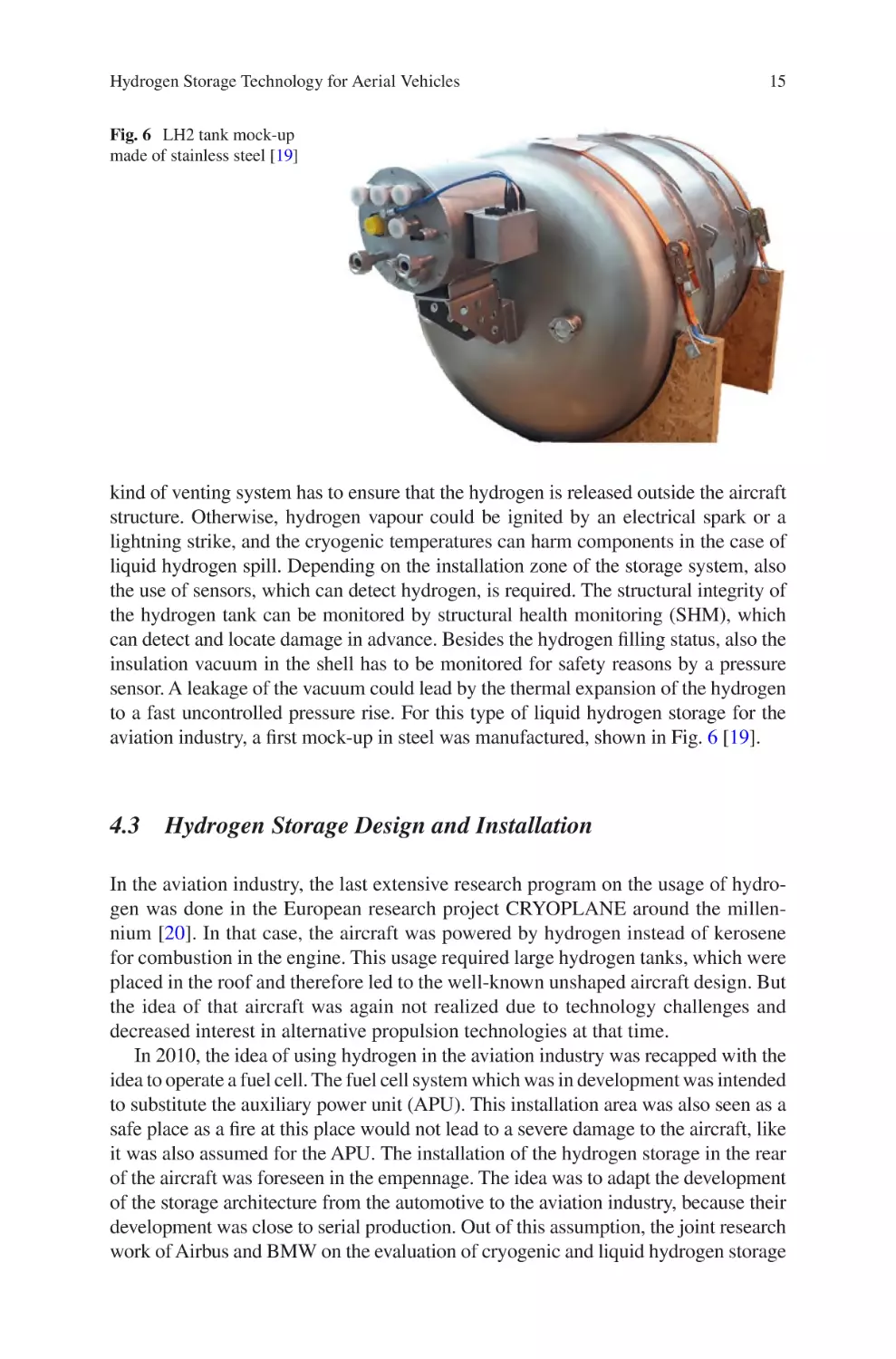
Fig. 6 LH2 tank mock-up
made of stainless steel [19]
kind of venting system has to ensure that the hydrogen is released outside the aircraft
structure. Otherwise, hydrogen vapour could be ignited by an electrical spark or a
lightning strike, and the cryogenic temperatures can harm components in the case of
liquid hydrogen spill. Depending on the installation zone of the storage system, also
the use of sensors, which can detect hydrogen, is required. The structural integrity of
the hydrogen tank can be monitored by structural health monitoring (SHM), which
can detect and locate damage in advance. Besides the hydrogen filling status, also the
insulation vacuum in the shell has to be monitored for safety reasons by a pressure
sensor. A leakage of the vacuum could lead by the thermal expansion of the hydrogen
to a fast uncontrolled pressure rise. For this type of liquid hydrogen storage for the
aviation industry, a first mock-up in steel was manufactured, shown in Fig. 6 [19].
4.3 Hydrogen Storage Design and Installation
In the aviation industry, the last extensive research program on the usage of hydrogen was done in the European research project CRYOPLANE around the millennium [20]. In that case, the aircraft was powered by hydrogen instead of kerosene
for combustion in the engine. This usage required large hydrogen tanks, which were
placed in the roof and therefore led to the well-known unshaped aircraft design. But
the idea of that aircraft was again not realized due to technology challenges and
decreased interest in alternative propulsion technologies at that time.
In 2010, the idea of using hydrogen in the aviation industry was recapped with the
idea to operate a fuel cell. The fuel cell system which was in development was intended
to substitute the auxiliary power unit (APU). This installation area was also seen as a
safe place as a fire at this place would not lead to a severe damage to the aircraft, like
it was also assumed for the APU. The installation of the hydrogen storage in the rear
of the aircraft was foreseen in the empennage. The idea was to adapt the development
of the storage architecture from the automotive to the aviation industry, because their
development was close to serial production. Out of this assumption, the joint research
work of Airbus and BMW on the evaluation of cryogenic and liquid hydrogen storage
16
D. Kastell
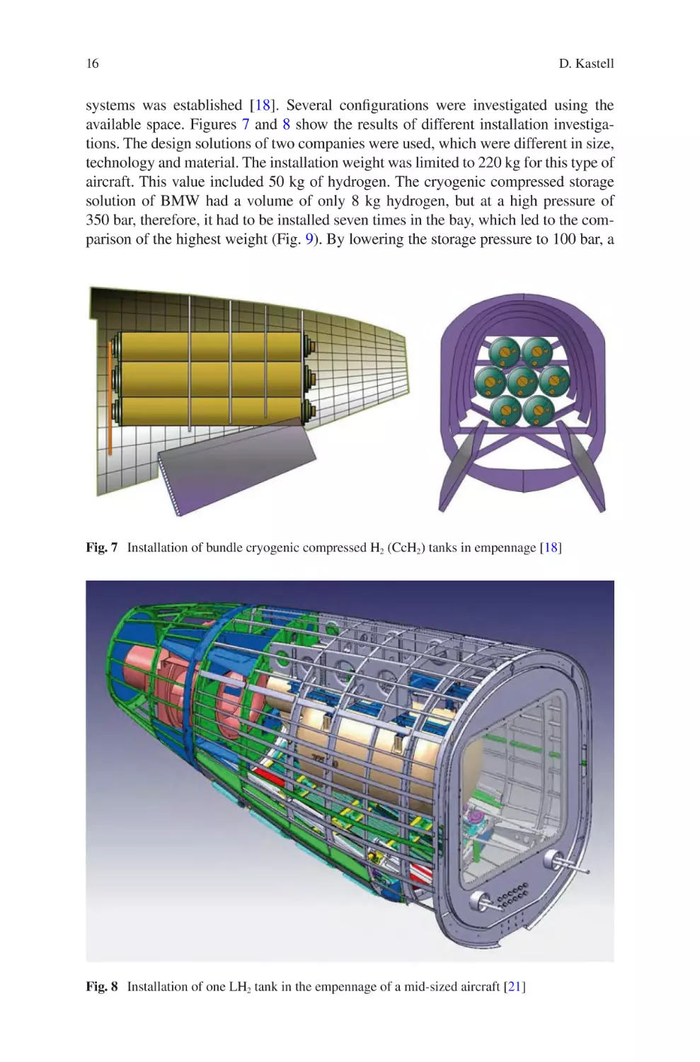
systems was established [18]. Several configurations were investigated using the
available space. Figures 7 and 8 show the results of different installation investigations. The design solutions of two companies were used, which were different in size,
technology and material. The installation weight was limited to 220 kg for this type of
aircraft. This value included 50 kg of hydrogen. The cryogenic compressed storage
solution of BMW had a volume of only 8 kg hydrogen, but at a high pressure of
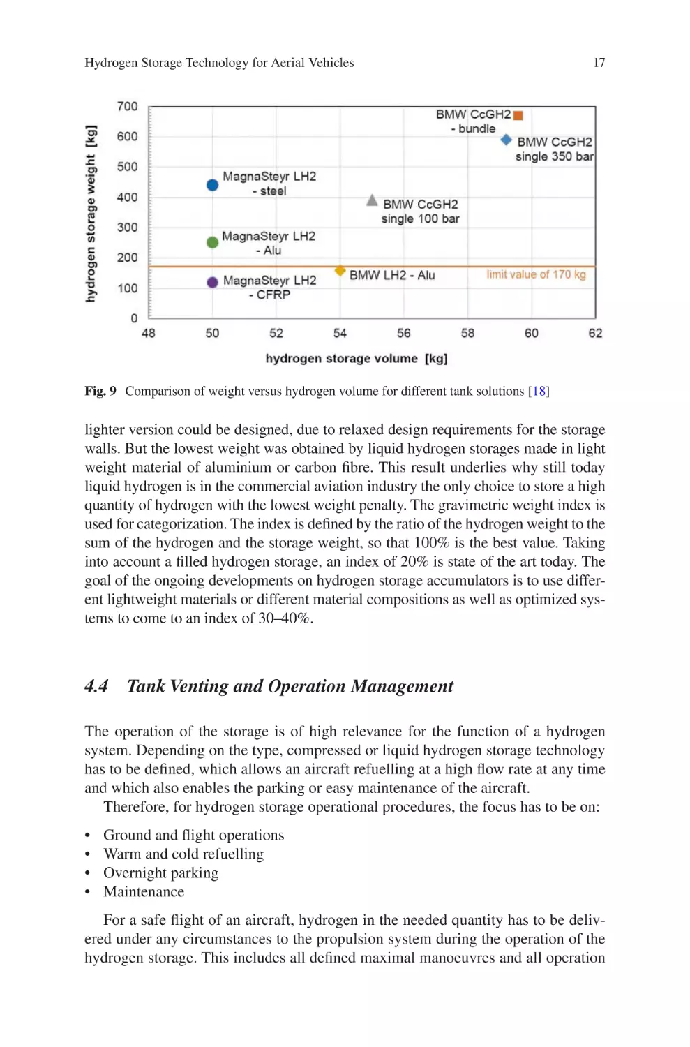
350 bar, therefore, it had to be installed seven times in the bay, which led to the comparison of the highest weight (Fig. 9). By lowering the storage pressure to 100 bar, a
Fig. 7 Installation of bundle cryogenic compressed H2 (CcH2) tanks in empennage [18]
Fig. 8 Installation of one LH2 tank in the empennage of a mid-sized aircraft [21]
Hydrogen Storage Technology for Aerial Vehicles
17
Fig. 9 Comparison of weight versus hydrogen volume for different tank solutions [18]
lighter version could be designed, due to relaxed design requirements for the storage
walls. But the lowest weight was obtained by liquid hydrogen storages made in light
weight material of aluminium or carbon fibre. This result underlies why still today
liquid hydrogen is in the commercial aviation industry the only choice to store a high
quantity of hydrogen with the lowest weight penalty. The gravimetric weight index is
used for categorization. The index is defined by the ratio of the hydrogen weight to the
sum of the hydrogen and the storage weight, so that 100% is the best value. Taking
into account a filled hydrogen storage, an index of 20% is state of the art today. The
goal of the ongoing developments on hydrogen storage accumulators is to use different lightweight materials or different material compositions as well as optimized systems to come to an index of 30–40%.
4.4 Tank Venting and Operation Management
The operation of the storage is of high relevance for the function of a hydrogen
system. Depending on the type, compressed or liquid hydrogen storage technology
has to be defined, which allows an aircraft refuelling at a high flow rate at any time
and which also enables the parking or easy maintenance of the aircraft.
Therefore, for hydrogen storage operational procedures, the focus has to be on:
•
•
•
•
Ground and flight operations
Warm and cold refuelling
Overnight parking
Maintenance
For a safe flight of an aircraft, hydrogen in the needed quantity has to be delivered under any circumstances to the propulsion system during the operation of the
hydrogen storage. This includes all defined maximal manoeuvres and all operation
18
D. Kastell
environments of the aircraft. These requirements imply that a tilting and rotating of
the storage and different temperature and pressures have to be taken into account for
the design of the storage and its supply system. These facts are the main requirements for aircraft certification. In some cases, this can be ensured by a back-up tank
and supply system, with two extraction pipes or pumps. So hydrogen has to be distributed to one or multiple tanks in the aircraft. Nevertheless, this architecture comes
along with an additional weight penalty.
It has to be kept in mind that hydrogen as a gas during compression increases in
temperature. Therefore, refuelling can cause an increase in pressure and temperature in the tank. This would result in a lower hydrogen volume in the tank at the end
of the refuelling procedure for a given fill pressure. This partial fill can be significant
for fast refills. Therefore, tests and qualification of all hydrogen components in the
temperature range from −260 °C to ambient and under pressure conditions ranging
from high vacuum to 1000 bar hydrogen atmosphere are needed. On ground, precooling can lower the temperature and consequently the pressure of the gas going
into the tank to maximize the hydrogen filling volume. The adequate filling procedure plays a relevant role in the optimization of the procedure. Therefore, many
investigations in the past and today are conducted on the right definition of this
process [18].
The integration of a permanently installed tank consequently leads to the need
for a filling device. Especially for liquid hydrogen (temperature ~−253 °C), the
distance between the refuelling vehicle and the tank should be as short as possible,
so that the evaporation losses are minimized. The same applies to the gap between
the tank coupling and the tank. Ideally, there is a gradient between clutch and tank
on the aircraft side, so that hydrogen flows into the tank even in the event of malfunctions (e.g. failure of the filling pumps). A standard coupling as an interface to
refill is needed in alignment with other mobility sectors that allows a safe, reliable
operation by the ground staff.
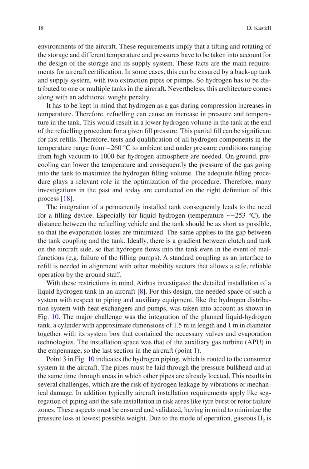
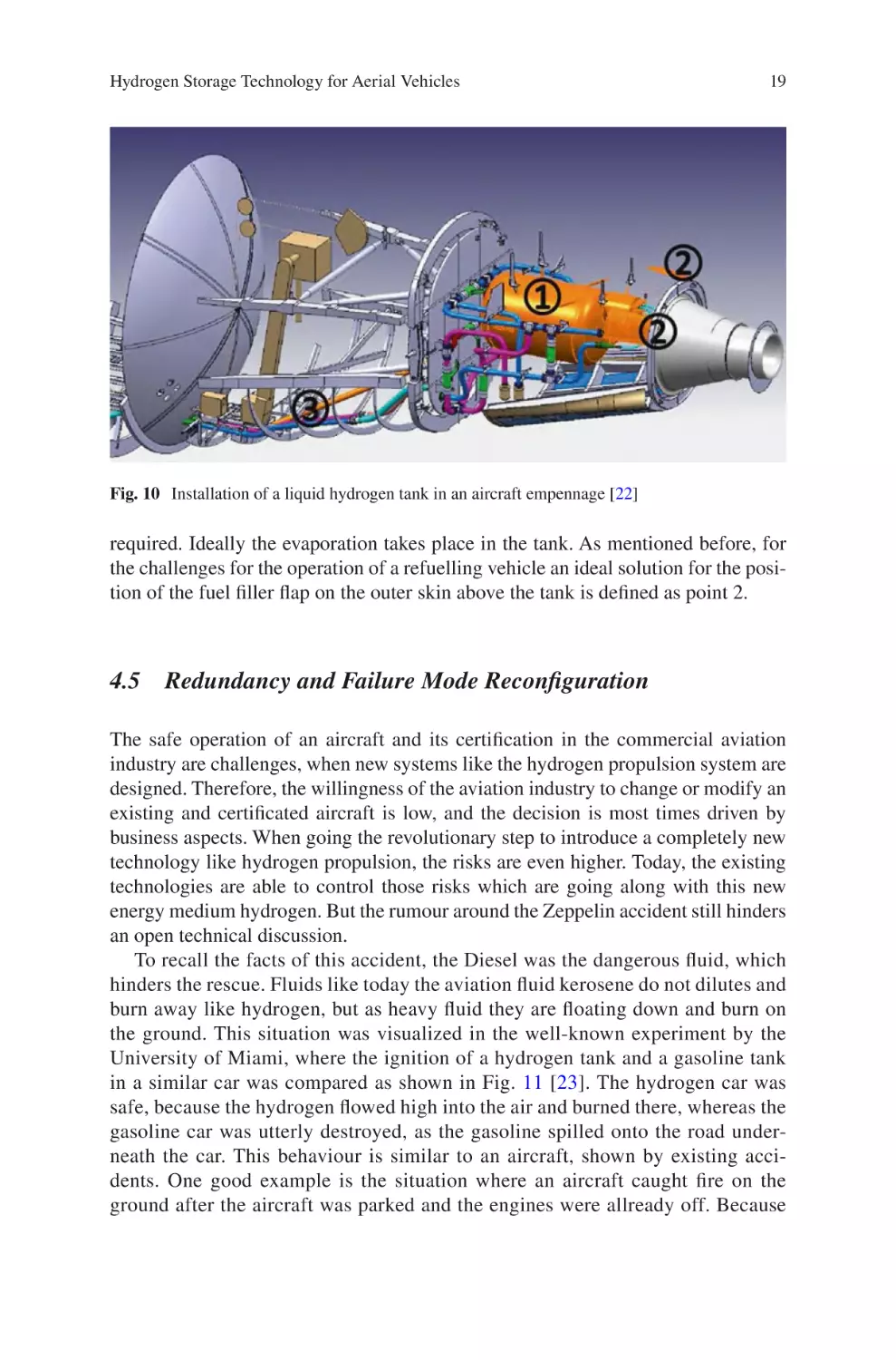
With these restrictions in mind, Airbus investigated the detailed installation of a
liquid hydrogen tank in an aircraft [8]. For this design, the needed space of such a
system with respect to piping and auxiliary equipment, like the hydrogen distribution system with heat exchangers and pumps, was taken into account as shown in
Fig. 10. The major challenge was the integration of the planned liquid-hydrogen
tank, a cylinder with approximate dimensions of 1.5 m in length and 1 m in diameter
together with its system box that contained the necessary valves and evaporation
technologies. The installation space was that of the auxiliary gas turbine (APU) in
the empennage, so the last section in the aircraft (point 1).
Point 3 in Fig. 10 indicates the hydrogen piping, which is routed to the consumer
system in the aircraft. The pipes must be laid through the pressure bulkhead and at
the same time through areas in which other pipes are already located. This results in
several challenges, which are the risk of hydrogen leakage by vibrations or mechanical damage. In addition typically aircraft installation requirements apply like segregation of piping and the safe installation in risk areas like tyre burst or rotor failure
zones. These aspects must be ensured and validated, having in mind to minimize the
pressure loss at lowest possible weight. Due to the mode of operation, gaseous H2 is
Hydrogen Storage Technology for Aerial Vehicles
19
Fig. 10 Installation of a liquid hydrogen tank in an aircraft empennage [22]
required. Ideally the evaporation takes place in the tank. As mentioned before, for
the challenges for the operation of a refuelling vehicle an ideal solution for the position of the fuel filler flap on the outer skin above the tank is defined as point 2.
4.5 Redundancy and Failure Mode Reconfiguration
The safe operation of an aircraft and its certification in the commercial aviation
industry are challenges, when new systems like the hydrogen propulsion system are
designed. Therefore, the willingness of the aviation industry to change or modify an
existing and certificated aircraft is low, and the decision is most times driven by
business aspects. When going the revolutionary step to introduce a completely new
technology like hydrogen propulsion, the risks are even higher. Today, the existing
technologies are able to control those risks which are going along with this new
energy medium hydrogen. But the rumour around the Zeppelin accident still hinders
an open technical discussion.
To recall the facts of this accident, the Diesel was the dangerous fluid, which
hinders the rescue. Fluids like today the aviation fluid kerosene do not dilutes and
burn away like hydrogen, but as heavy fluid they are floating down and burn on
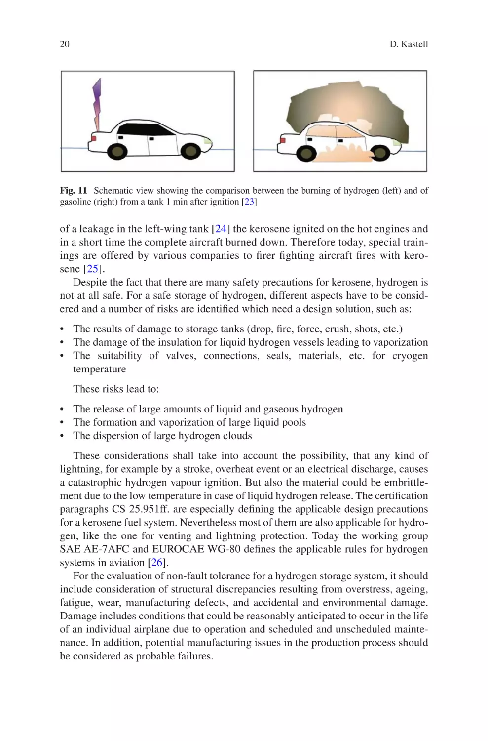
the ground. This situation was visualized in the well-known experiment by the
University of Miami, where the ignition of a hydrogen tank and a gasoline tank
in a similar car was compared as shown in Fig. 11 [23]. The hydrogen car was
safe, because the hydrogen flowed high into the air and burned there, whereas the
gasoline car was utterly destroyed, as the gasoline spilled onto the road underneath the car. This behaviour is similar to an aircraft, shown by existing accidents. One good example is the situation where an aircraft caught fire on the
ground after the aircraft was parked and the engines were allready off. Because
20
D. Kastell
Fig. 11 Schematic view showing the comparison between the burning of hydrogen (left) and of
gasoline (right) from a tank 1 min after ignition [23]
of a leakage in the left-wing tank [24] the kerosene ignited on the hot engines and
in a short time the complete aircraft burned down. Therefore today, special trainings are offered by various companies to firer fighting aircraft fires with kerosene [25].
Despite the fact that there are many safety precautions for kerosene, hydrogen is
not at all safe. For a safe storage of hydrogen, different aspects have to be considered and a number of risks are identified which need a design solution, such as:
• The results of damage to storage tanks (drop, fire, force, crush, shots, etc.)
• The damage of the insulation for liquid hydrogen vessels leading to vaporization
• The suitability of valves, connections, seals, materials, etc. for cryogen
temperature
These risks lead to:
• The release of large amounts of liquid and gaseous hydrogen
• The formation and vaporization of large liquid pools
• The dispersion of large hydrogen clouds
These considerations shall take into account the possibility, that any kind of
lightning, for example by a stroke, overheat event or an electrical discharge, causes
a catastrophic hydrogen vapour ignition. But also the material could be embrittlement due to the low temperature in case of liquid hydrogen release. The certification
paragraphs CS 25.951ff. are especially defining the applicable design precautions
for a kerosene fuel system. Nevertheless most of them are also applicable for hydrogen, like the one for venting and lightning protection. Today the working group
SAE AE-7AFC and EUROCAE WG-80 defines the applicable rules for hydrogen
systems in aviation [26].
For the evaluation of non-fault tolerance for a hydrogen storage system, it should
include consideration of structural discrepancies resulting from overstress, ageing,
fatigue, wear, manufacturing defects, and accidental and environmental damage.
Damage includes conditions that could be reasonably anticipated to occur in the life
of an individual airplane due to operation and scheduled and unscheduled maintenance. In addition, potential manufacturing issues in the production process should
be considered as probable failures.
Hydrogen Storage Technology for Aerial Vehicles
21
The determination of the worst-case failures should be addressed, which can
occur in service due to ageing and wear. Depending on the configuration of the
aircraft, it is also needed to analyse all cases of a hydrogen tank being hit by
some projectile, like a piece of debris from an uncontained engine or tyre failure.
If such an analysis would result in a catastrophic scenario, tanks have to be
arranged outside of these specified areas. In such a case also the redundancy of
the system has to be assessed, because a single failure is not allowed to lead to a
complete loss of the hydrogen supply, as an aircraft is not able to land at any
place and time.
For the final certification of an aviation hydrogen storage, different kinds of qualification tests have to be performed according to the aviation regulations following
the DO160 standard [16], which are:
––
––
––
––
––
––
Proof and burst pressure tests
Pressure and thermal cycling tests
Vacuum (insulation) loss and bonfire
External impact analysis
Cryogenic sloshing pressure effect
Shock and vibration impact
5 Concluding Remarks
The appropriate architecture, design and installation of a hydrogen storage are crucial for the reliable operation of a hydrogen system in an aircraft.To ensure this, a
proper selection of the storage method depending on the type of aircraft and its
operational range and environment has to be done. For a commercial aircraft the
usage of liquid hydrogen is the only feasible solution today, having in mind technology maturity, storage size and reachable distances. This need is totally different to
the one of a commuter aircraft or an unmanned vehicle. Even for the last categories
one can distinguish between large tactical vehicles which have to stay for a long
time in the air or the today popular drones, which are in most cases only used for a
short time for observation or transportation of goods. In the end, the architect of the
flight vehicle has to decide, which hydrogen storage solution has the best value for
his device, taking into account cost, quality, capacity, safety and usage time of the
storage system.
References
1. L. Tittel: 1936–1937 LZ 129 “Hindenburg—1937–1987 50 Jahre Unglück von Lakehurst” In
“Schriften zur Geschichte der Zeppelin-Luftschiffahrt Nr. 5”. Gessler, ISBN 3-926162-55-4,
S. 23. 1987
2. J. Klier; M. Rattey; G. Kaiser; M. Klupsch; A. Kade; M. Schneider; R. Herzog: A new cryogenic high-pressure H2 test area: First results. Proceedings of the 12th IIR International
Conference: Dresden, Germany, Sept. 2012
22
D. Kastell
3. K. Kunze, O. Kirche: CRYO-COMPRESSED HYDROGEN STORAGE, Cryogenic cluster
day, Oxford, Sept. 2012
4. S. Schäfer, S. Maus: Technology Pitch: Subcooled Liquid Hydrogen (sLH2), NOW & CEP
Heavy Duty Event, April 2021
5. R. K. Ahluwalia, T. Q. Hua, J-K Peng, S. Lasher, K. McKenney, and J. Sinha: Technical
Assessment of Cryo-Compressed Hydrogen Storage Tank Systems for Automotive
Applications, Argonne National Laboratory, ANL/09-33, Dec. 2009
6. L. Schlapbach, A. Züttel: Hydrogen-storage materials for mobile applications, Nature 414:
pp. 353–358, 2002
7. L. Klebanoff, J. Keller: Final Report for the DOE Metal Hydride Center of Excellence, Sandia
National Laboratories, SAND2012-0786, Feb. 2012
8. M. Vogt, L- Röntzsch: Power Paste—Energy Storage Solution, Fraunhofer Gesellschaft, Flyer,
also in FORSCHUNG KOMPAKT, Feb 2021
9. K. C. Ott, S. Linehan, F. Lipiecki, C. L. Aardahl: Down Select Report of Chemical Hydrogen
Storage Materials, Catalysts, and Spent Fuel Regeneration Processes, Chemical Hydrogen
Storage Center of Excellence, FY2008 Second Quarter Milestone Report, May 2008
10. G. Thomas and G. Parks, Potential Roles of Ammonia in a Hydrogen Economy, Feb. 2006
11. M. Hurskainen: Liquid organic hydrogen carriers (LOHC): Concept evaluation and techno-
economics. VTT Technical Research Centre of Finland. Report No. VTT-R-00057-19,
Dec. 2019
12. R. Ströbel, J. Garche, P.T. Moseley, L. Jörissen, G. Wolf: Hydrogen storage by carbon materials, Journal of Power Sources, 159, pp. 781–801, 2006
13. J. Kleperis, P. Lesnicenoks, L. Grinberga, G. Chikvaidze, J. Klavins: Zeolite as material for
hydrogen storage in transport applications, Latvian Journal of Physics and Technical Sciences
50(3), pp. 59–64, June 2013
14. M. S. Turnbull: Hydrogen Storage in Zeolites: Activation of the pore space through incorporation of guest materials, PhD Thesis, University of Birmingham, March 2010
15. A. Züttel: Hydrogen Storage Methods, Naturwissenschaften, 91, pp. 157172, April 2004
16. RTCA DO-160G: Environmental Conditions and Test Procedures for Airborne Equipment;
RTCA DO-178C: Software Considerations in Airborne Systems and Equipment Certification;
RTCA DO-254: Design Assurance Guidance for Airborne Electronic Hardware
17. EASA (European Aviation Safety Agency): CS25. Certification Specifications for Large
Aeroplanes; Amendment 26; CS23: Certification Specifications for Normal-Category
Aeroplanes
18. O. Kircher, E. Saefkow, B. Strauß, T. Jordan: CryoSys—Systemvalidierung Kryodruck-
Fahrzeugtank, Final Report, Luftfahrtforschungsprogram LUFO IV-4 German research program, final report, May 2012
19. B. Pessl: Innovative Hydrogen Storage Systems A3PS Eco-Mobility. Tech Gate, Vienna,
Austria, October 2014
20. A. Westernberger: CRYOPLANE—Liquid Hydrogen Fuelled Aircraft—System Analysis,
European funding program FP5-GROWTH, final report, Sept. 2003
21. D. Kastell, ECOCENTS—Effizientes Cooling Center für Flugzeugsysteme,
Luftfahrtforschungsprogramm LUFO IV-2, German research program, final report, Feb. 2013
22. D. Kastell: FUCHS—Fuel Cell and Hydrogen System, Luftfahrtforschungsprogramm LUFO
IV-4, German research program, final report, April 2017
23. M. Swain: Fuel Leak Simulation, Proceedings of the 2001 DOE Hydrogen Program Review,
NREL/CP-570-30535
24. Japan Transport Safety Board: AIRCRAFT ACCIDENT INVESTIGATION REPORT CHINA
AIRLINES—B18616; August 2009
25. https://www.draeger.com/en-us_us/Products/Aircraft-fire-training-systems
26. O. Savin: Standardization Activities on Hydrogen & Fuel Cell Technologies for Airborne
Applications, DOE’s H2@Airports Virtual Workshop, Nov. 2020
27. M. Sippel, A. Kopp: Progress on Advanced Cryo-Tanks Structural Design Achieved in
CHATT-Project, ECSSMET—European Conference on Spacecraft Structures, Materials and
Environmental Testing, Sept. 2016
Liquid Hydrogen – Status and Trends as
potential Aviation Fuel
Michael Bracha
1 Introduction
Liquid hydrogen (LH2) has been the standard fuel in the space industry since the
start of the American “Apollo” project, which in 1969 enabled the first manned
landing on the moon. Already at that period, NASA investigated possibilities to use
LH2 as propellant for civil aviation as well. But only now hydrogen is getting more
focus in the aviation industry for the next generation of aircrafts. Two strong drivers
are the reason for this development. Driver one is the environmental aspect with
climatic change, CO2 emissions, and likewise “peak-oil” which is not in the headlines but can already be felt as, e.g., by the massive decline of the North Sea oil
resources. The other one is the unprecedented development of the hydrogen market
in the last years which is characterized by strongly growing market applications and
by foreseeable falling prices for green hydrogen in the future.
The combination of these two effects has now triggered the aviation industry to
start development of hydrogen-powered aircraft. Probably, the further deployment
will take place by two different trends. The first one is the field of small aircraft and
general aviation, where hydrogen can be used via fuel cells or modified turbines.
The first aircrafts of this category are being already tested and could be market-
ready in the next years. Hydrogen supply concepts for these aviation applications
still have to be developed in parallel and under aviation-specific boundary conditions, but due to the limited hydrogen quantities required for this application, there
should be no show-stopper. The second category is large commercial aircraft that
dominates the international aviation industry. This aircraft requires much more time
for development, and likewise, also the corresponding new LH2 infrastructure is a
M. Bracha (*)
Michael Bracha - H2 Coaching und Seminare, Munich, Germany
e-mail: info@h2partnermunich.com
© The Author(s), under exclusive license to Springer Nature Switzerland AG 2022
C. O. Colpan, A. Kovač (eds.), Fuel Cell and Hydrogen Technologies in Aviation,
Sustainable Aviation, https://doi.org/10.1007/978-3-030-99018-3_2
23
24
M. Bracha
challenging long-term project. In addition, the ramp-up of the airport infrastructure
has to enable a parallel operation of kerosene and hydrogen-operated aircraft.
The main challenge will be the substitution of the enormous quantities of kerosene by green hydrogen consumed in aviation worldwide. Detail engineering will
lead to new technologies for aviation, but a good basis therefore should already be
available by the presently ongoing infrastructure development for cars, buses,
trucks, trains, and—now impending—marine applications. As aviation is an international business, also international coordination and hardware standardization
have to follow this development already from an early stage.
2 Historical Review: LH2 in Aviation
and Industrial Liquefaction
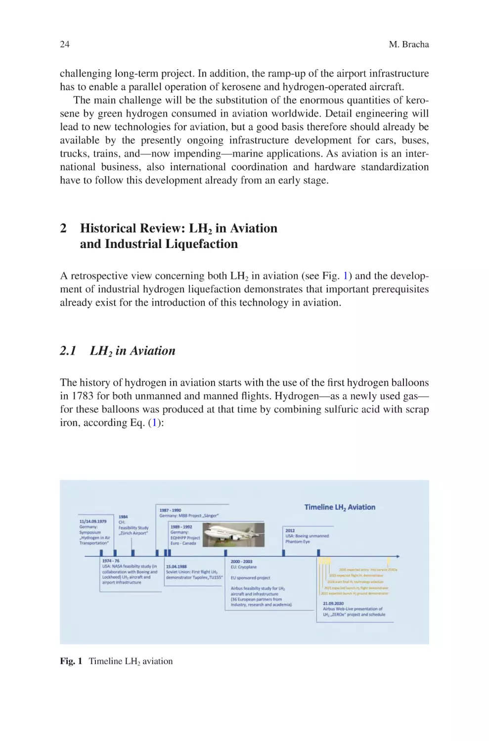
A retrospective view concerning both LH2 in aviation (see Fig. 1) and the development of industrial hydrogen liquefaction demonstrates that important prerequisites
already exist for the introduction of this technology in aviation.
2.1 LH2 in Aviation
The history of hydrogen in aviation starts with the use of the first hydrogen balloons
in 1783 for both unmanned and manned flights. Hydrogen—as a newly used gas—
for these balloons was produced at that time by combining sulfuric acid with scrap
iron, according Eq. (1):
Fig. 1 Timeline LH2 aviation
Liquid Hydrogen – Status and Trends as potential Aviation Fuel
2 Fe 3H 2 SO 4 1 / 2O2
air
Fe 2
SO 4
3 H 2 O 2H 2
25
(1)
The era of the hydrogen balloons was later followed by the era of ‘airships’ that
ended quite abruptly with the famous Hindenburg accident on 6 May 1937 at
Lakehurst.
The use of liquid hydrogen in aviation, however, began in 1955/1956 with the
American B57-Canberra project. This two-engine demonstrator aircraft was operated with hydrogen in one engine on several test flights, hydrogen being stored in a
LH2 tank in one of the wings. These successful tests later initiated an engine test
program in the years 1956–1958 at Pratt & Whitney on behalf of the US Air
Force [1, 2].
Several years later in 1974–1976, NASA started investigations for use of liquid
hydrogen in commercial aviation. While today the driver for the development of
hydrogen aviation is the concern of global warming and CO2 emissions, it was at
that time the concern of limited availability of fossil fuels (peak oil) when the “oil
crisis” took place. Following the awareness that both the development of a new kind
of hydrogen aircraft and the build-up of an adequate airport infrastructure would at
least require one to two decades, the intention of the NASA study was to start
already detailed investigations in order to have the technology available by the turn
of the century. Several types of subsonic and hypersonic aircraft were studied. The
design of an airport hydrogen infrastructure was contracted as study to Lockheed
for San Francisco International Airport (SFO) while Boeing was assigned Chicago
O’Hare International Airport (ORD) as reference airport. From today’s perspective,
the results of these detailed studies still represent a profound engineering basis for
an airport infrastructure [3].
In context with the initiative taken by NASA, an international symposium called
“Hydrogen in Air Transportation” was held at Stuttgart, Germany in 1979, where
experts also discussed on design concepts for LH2 airport facilities and hydrogen
aircraft technology. Also, this symposium was concerned about the necessity for an
early start of the long-term development program as it was expressed by Willis
M. Hawkins from Lockheed Corporation in his introduction with the words: “My
hope is that we can somehow wake up our system to be better prepared with alternatives when that inevitable day comes” [4].
Another feasibility study (1982) checked the possibility to install a small LH2
infrastructure at the Zürich airport. Basis for this study was the scenario of one
cargo aircraft flight per day with an onsite production capacity of 15–30 t/d (tons per
day) LH2. The LH2 production installation was planned to be located between runways Kilo and November for direct refueling the aircraft without use of tank-
trucks [5].
Some years later (1987–1990), the former German aviation and space company
MBB (Messerschmitt-Bölkow-Blohm) reactivated a project for a space transport
system that originally the German engineer Eugen Sänger had conceived. This project officially called “Sänger” was planned as two-stage LH2 system having a scramjet (airbreathing jet engine with combustion taking place in supersonic airflow) in
the upper stage enabling hypersonic travel. However, like several similar projects,
26
M. Bracha
e.g., the American NASP project (National Aero Space Plan), also the Sänger project was never realized.
Contrary to these ambitious plans for space travel, the former Soviet Union presented a demonstrator aircraft with liquid hydrogen, which had its maiden flight on
April 15, 1988. This three-engine aircraft Tupolev Tu-155 (one engine H2 operated)
was a special development on the basis of the “workhorse” Tu-154, which was
known as one of the most successful Soviet and Russian aircrafts for several
decades. Tu-155 was designed for both the operation with liquid hydrogen on board
and the operation with LNG (liquid natural gas). LNG was considered as relatively
long-term available potential fuel with sufficient sources in the Soviet Union. More
than 100 test flights were executed, the majority thereof with LNG (maiden flight
January 18, 1989), however, LH2 operation was also successfully demonstrated as
feasible for commercial aviation [6, 7].
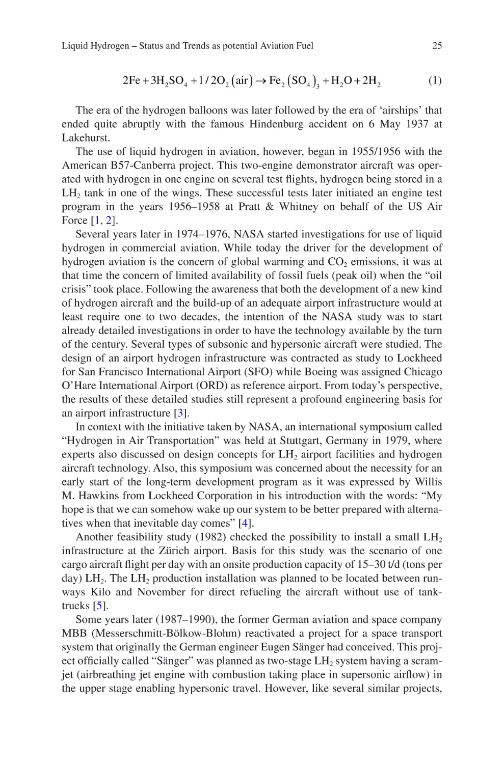
A feasibility study named EQHHPP (Euro-Quebec Hydro-Hydrogen Pilot
Project) was conducted in 1989–1991, which for the first time examined the whole
production, supply and application chain of renewable hydrogen produced in
Canada and consumed in Europe. Among the various applications, also the concept
of a hydrogen powered aircraft (see Fig. 2) was studied by Deutsche Airbus GmbH
at that time including later tests for NOx reduction of the H2 turbine [8].
In the following years, several German–Russian initiatives and smaller studies
were initiated to continue development on this LH2 aircraft concept; however, a new
big approach was then taken within the frame of an EU project called “Cryoplane.”
This project started in April 2000 with 35 partners from industry, research and academia from 11 European countries and was coordinated by Airbus Hamburg. All
relevant aspects were covered in this comprehensive study, as design of the aircraft,
LH2 tank and propulsion technologies, infrastructure issues, environmental
Fig. 2 EQHHPP project: LH2 aircraft. By courtesy of LBST
Liquid Hydrogen – Status and Trends as potential Aviation Fuel
27
compatibility, and safety. The system analysis showed that the concept was viable,
no showstoppers were identified. Unfortunately, the next logical step of building up
test facilities and a demonstrator aircraft was not taken and the project expired [9].
In July 2010, Boeing’s “Phantom Eye” was presented to the public. The Phantom
Eye is an unmanned drone with liquid hydrogen tank that benefits from LH2 by high
range and especially long operational times of more than 4 days [10].
Meanwhile especially manufacturers of smaller aircraft have started several projects for new or modified aircraft with hydrogen propulsion, some of them have
already been flight tested, e.g., ZeroAvia [11, 12]. Common to all these projects is
the use of hydrogen as propellant, whereas engine technology and hydrogen storage
may vary. For smaller aircraft, fuel cells are often the preferred choice that deliver
the electricity for the electrical motors. Hydrogen may be stored as compressed gas
or liquid, the tanks itself may be designed as fixed aircraft tanks or as exchangeable
modules, where the tank in the aircraft is not refueled but the empty tank module is
exchanged by a filled one [13, 14].
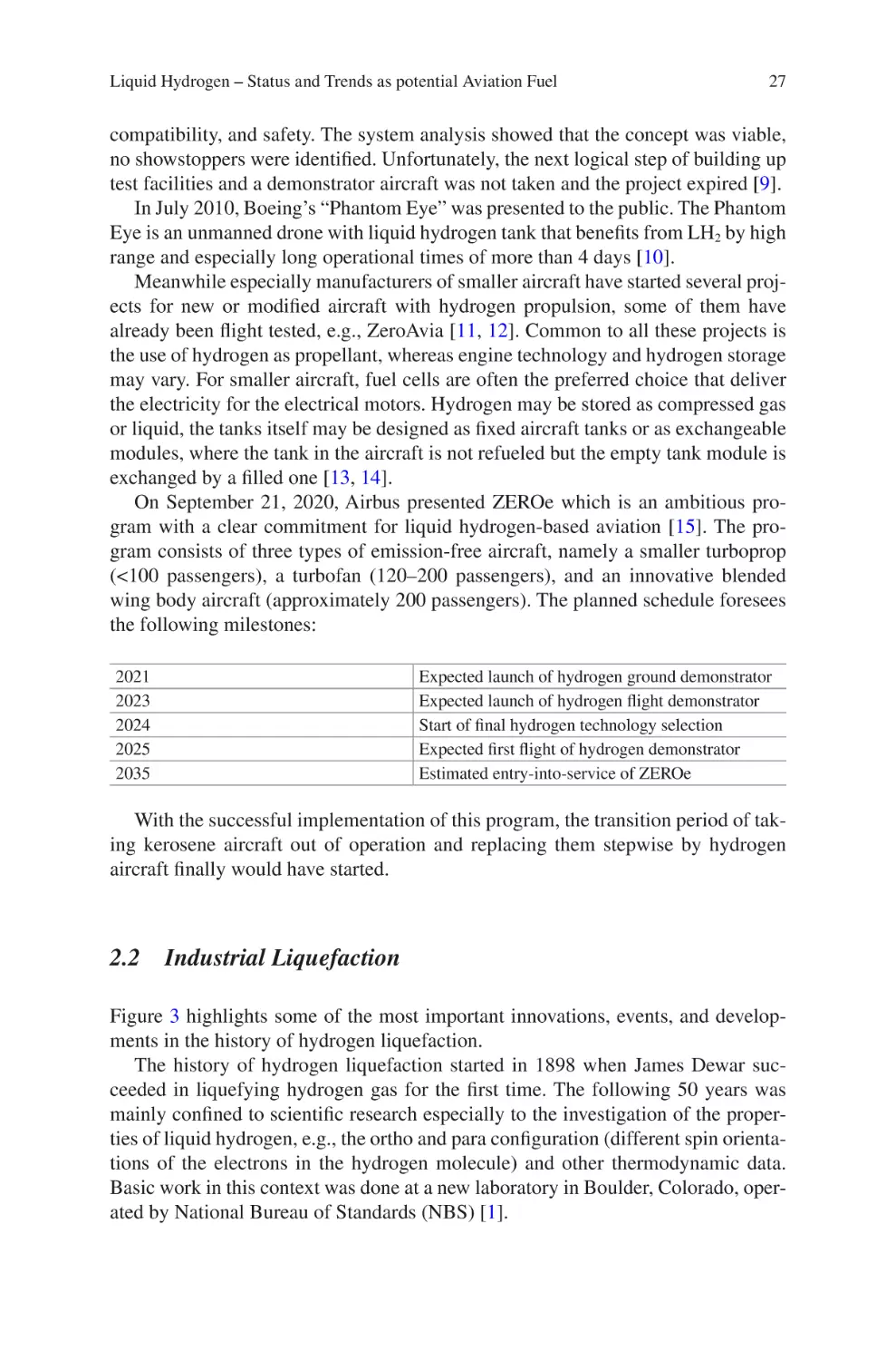
On September 21, 2020, Airbus presented ZEROe which is an ambitious program with a clear commitment for liquid hydrogen-based aviation [15]. The program consists of three types of emission-free aircraft, namely a smaller turboprop
(<100 passengers), a turbofan (120–200 passengers), and an innovative blended
wing body aircraft (approximately 200 passengers). The planned schedule foresees
the following milestones:
2021
2023
2024
2025
2035
Expected launch of hydrogen ground demonstrator
Expected launch of hydrogen flight demonstrator
Start of final hydrogen technology selection
Expected first flight of hydrogen demonstrator
Estimated entry-into-service of ZEROe
With the successful implementation of this program, the transition period of taking kerosene aircraft out of operation and replacing them stepwise by hydrogen
aircraft finally would have started.
2.2 Industrial Liquefaction
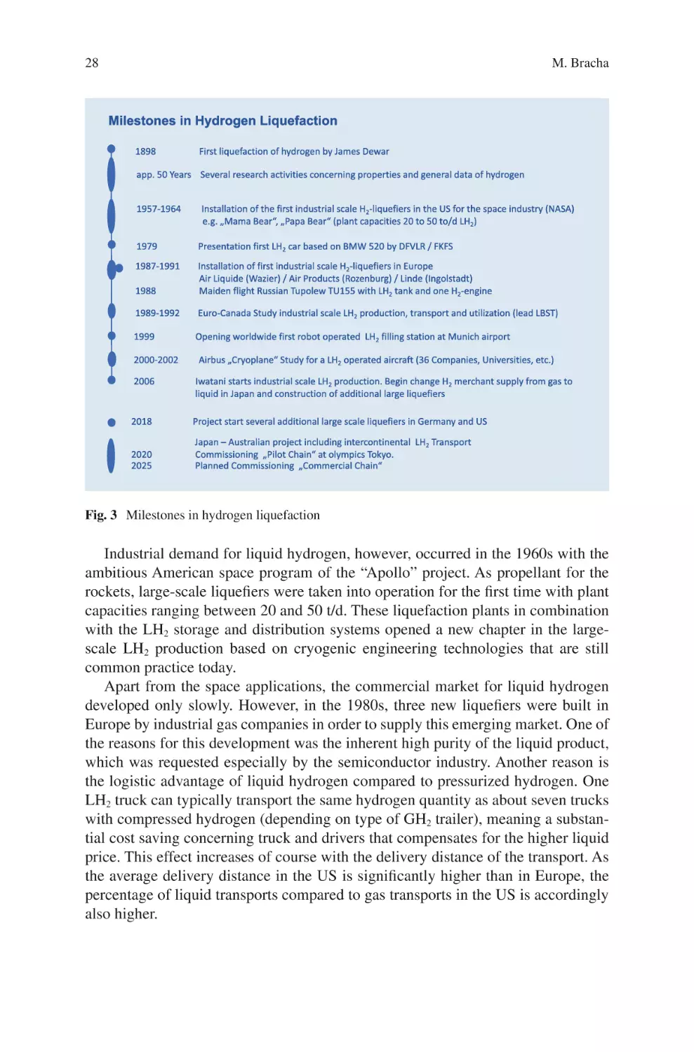
Figure 3 highlights some of the most important innovations, events, and developments in the history of hydrogen liquefaction.
The history of hydrogen liquefaction started in 1898 when James Dewar succeeded in liquefying hydrogen gas for the first time. The following 50 years was
mainly confined to scientific research especially to the investigation of the properties of liquid hydrogen, e.g., the ortho and para configuration (different spin orientations of the electrons in the hydrogen molecule) and other thermodynamic data.
Basic work in this context was done at a new laboratory in Boulder, Colorado, operated by National Bureau of Standards (NBS) [1].
28
M. Bracha
Fig. 3 Milestones in hydrogen liquefaction
Industrial demand for liquid hydrogen, however, occurred in the 1960s with the
ambitious American space program of the “Apollo” project. As propellant for the
rockets, large-scale liquefiers were taken into operation for the first time with plant
capacities ranging between 20 and 50 t/d. These liquefaction plants in combination
with the LH2 storage and distribution systems opened a new chapter in the large-
scale LH2 production based on cryogenic engineering technologies that are still
common practice today.
Apart from the space applications, the commercial market for liquid hydrogen
developed only slowly. However, in the 1980s, three new liquefiers were built in
Europe by industrial gas companies in order to supply this emerging market. One of
the reasons for this development was the inherent high purity of the liquid product,
which was requested especially by the semiconductor industry. Another reason is
the logistic advantage of liquid hydrogen compared to pressurized hydrogen. One
LH2 truck can typically transport the same hydrogen quantity as about seven trucks
with compressed hydrogen (depending on type of GH2 trailer), meaning a substantial cost saving concerning truck and drivers that compensates for the higher liquid
price. This effect increases of course with the delivery distance of the transport. As
the average delivery distance in the US is significantly higher than in Europe, the
percentage of liquid transports compared to gas transports in the US is accordingly
also higher.
Liquid Hydrogen – Status and Trends as potential Aviation Fuel
29
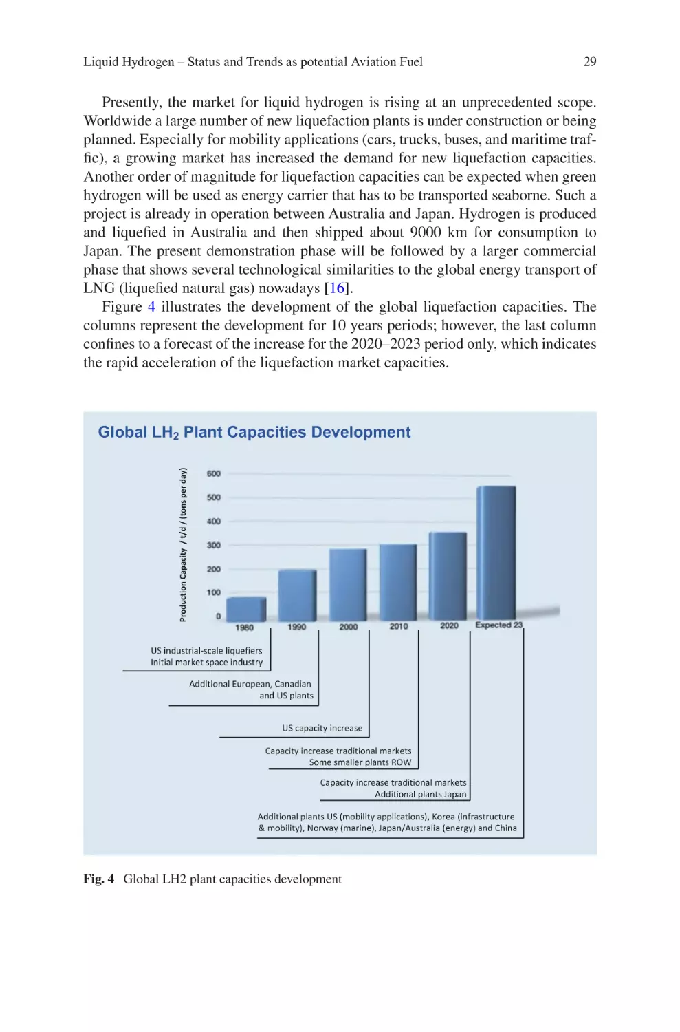
Presently, the market for liquid hydrogen is rising at an unprecedented scope.
Worldwide a large number of new liquefaction plants is under construction or being
planned. Especially for mobility applications (cars, trucks, buses, and maritime traffic), a growing market has increased the demand for new liquefaction capacities.
Another order of magnitude for liquefaction capacities can be expected when green
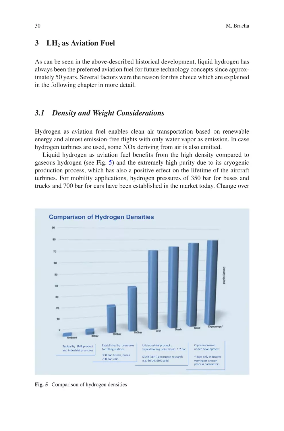
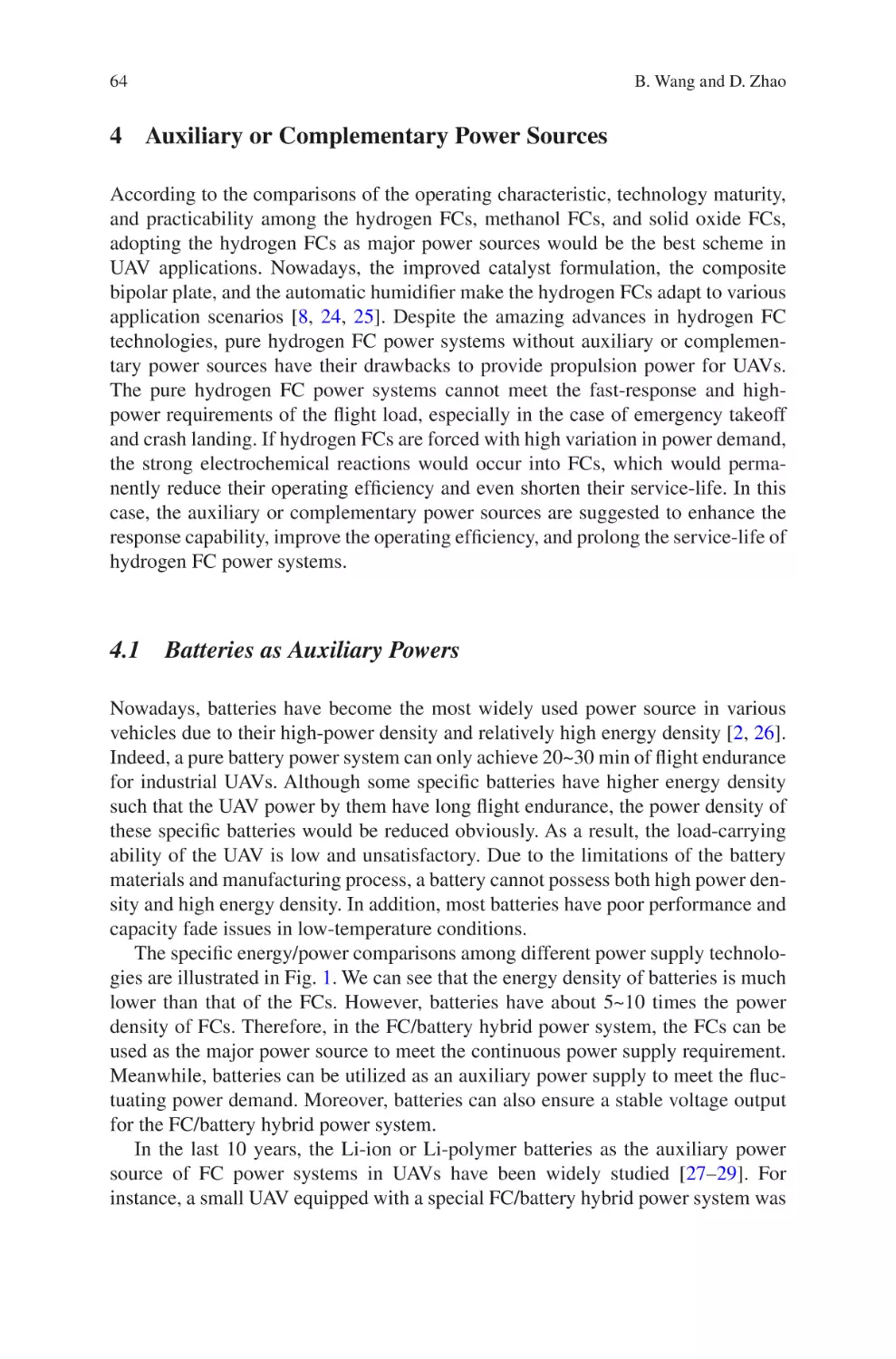
hydrogen will be used as energy carrier that has to be transported seaborne. Such a
project is already in operation between Australia and Japan. Hydrogen is produced
and liquefied in Australia and then shipped about 9000 km for consumption to
Japan. The present demonstration phase will be followed by a larger commercial
phase that shows several technological similarities to the global energy transport of
LNG (liquefied natural gas) nowadays [16].
Figure 4 illustrates the development of the global liquefaction capacities. The
columns represent the development for 10 years periods; however, the last column
confines to a forecast of the increase for the 2020–2023 period only, which indicates
the rapid acceleration of the liquefaction market capacities.
Production Capacity / t/d / (tons per day)
Global LH2 Plant Capacities Development
US industrial-scale liquefiers
Initial market space industry
Additional European, Canadian
and US plants
US capacity increase
Capacity increase traditional markets
Some smaller plants ROW
Capacity increase traditional markets
Additional plants Japan
Additional plants US (mobility applications), Korea (infrastructure
& mobility), Norway (marine), Japan/Australia (energy) and China
Fig. 4 Global LH2 plant capacities development
30
M. Bracha
3 LH2 as Aviation Fuel
As can be seen in the above-described historical development, liquid hydrogen has
always been the preferred aviation fuel for future technology concepts since approximately 50 years. Several factors were the reason for this choice which are explained
in the following chapter in more detail.
3.1 Density and Weight Considerations
Hydrogen as aviation fuel enables clean air transportation based on renewable
energy and almost emission-free flights with only water vapor as emission. In case
hydrogen turbines are used, some NOx deriving from air is also emitted.
Liquid hydrogen as aviation fuel benefits from the high density compared to
gaseous hydrogen (see Fig. 5) and the extremely high purity due to its cryogenic
production process, which has also a positive effect on the lifetime of the aircraft
turbines. For mobility applications, hydrogen pressures of 350 bar for buses and
trucks and 700 bar for cars have been established in the market today. Change over
Comparison of Hydrogen Densities
Typical H2 SMR product
and industrial pressures
Established H2 pressures
for filling stations
350 bar: trucks, buses
700 bar: cars
Fig. 5 Comparison of hydrogen densities
LH2 industrial product :
typical boiling point liquid 1.2 bar
Cryocompressed
under development
Slush (SLH2) aerospace research
e.g. 50 LH2 50% solid
* data only indicative
varying on chosen
process parameters
Liquid Hydrogen – Status and Trends as potential Aviation Fuel
31
Fig. 6 Comparison of energy densities
to liquid hydrogen enables almost a duplication of the density compared to 700 bar
storage.
In comparison with kerosene, liquid hydrogen has a three times higher gravimetric energy density but a volumetric energy density of about only one fourth (see
Fig. 6). This means that the LH2 fuel itself has a strong weight advantage, which is
an important factor in aviation. However, the aircraft empty weight of the LH2 version is generally higher since the tank is heavier than the kerosene storage in the
wings, and the larger tank volume also requires a different aircraft design with a
larger surface and fuselage volume. The refueled aircraft generally benefit from the
higher gravimetric density of hydrogen leading to a lower take-off weight which
also has a positive effect of reduced turbine power demand and a lower noise emission. The magnitude of this effect varies between the different aircraft types as
regional, short-, mid-, and long-range versions [17, 18].
3.2 Product Development LH2
Liquid hydrogen, which is a commonly used market product today, can be defined
as boiling point liquid at moderate pressure, e.g., 1.3 bar absolute. Between 1.0 and
1.5 bar absolute, the boiling point temperature varies between 20.3 and 21.7 K (data
for para-hydrogen). The small overpressure is foreseen as safety measure in order to
avoid leakage of other gases, e.g., air, into the product.
32
M. Bracha
The rapid development of hydrogen mobility applications has now initiated the
research on two other cryogenic products with similar properties as LH2 [19], namely.
–– CryoCompressed Hydrogen (cCH2) and
–– Subcooled Hydrogen (sLH2) (The abbreviation “sLH2” is also used for slush
hydrogen [mixture of liquid and solid hydrogen])
Both of them are presently subjects of research and development mainly for the
hydrogen storage in trucks, but these investigations are not confined to this application only. The cCH2 cycle between tank filling and H2 consumption is operated
above the critical pressure of hydrogen (critical point: 33.2 K/13.2 bar) and enables
a storage density even above LH2 (depending on selected p/T parameters). A rise of
the process pressure from 300 to 450 bar for example would result in a density of
about 80 kg/m3. The sLH2 cycle operates at a lower pressure level than the cCH2
cycle with correspondingly lower material requirements on the equipment as piping
and tank. The filling procedure of this cycle starts with subcooled LH2. Common
advantages of both systems compared to LH2 are the longer holding times before
venting and a simpler and quicker fueling process due to one phase flow without
cold gas return. Both cCH2 and sLH2 can be easily produced on the basis of LH2.
These practical advantages will probably open the way for a widespread use in
the mobility sector. If this is also applicable in the case of aircraft depends on the
future overall system detail engineering progress since especially the cCH2 system
presently requires heavier tanks due to the elevated operational pressure level.
3.3 Potential Future Synergies Based on Heat Sink
Potential of LH2
Storing hydrogen in liquid form on board the aircraft opens the way to apply some
innovative technologies based on the available heat sink utilization:
–– Laminar Flow Control (LFC) of the wings to reduce the skin friction drag:
Cooling a surface affects the critical Reynolds number by stabilizing the boundary layer. As a result, the fuel consumption of the aircraft could be significantly
reduced, provided the flight mission profile is executed to a large extent at high
flight level where ambient moisture will not pose a freezing problem [1, 3].
–– Cabin cooling: By heat exchange, the cabin air can be cooled effectively.
–– Turbine cooling: The LH2 heat sink can also be used for cooling purposes of the
engine and the thermal management, although this benefit has to be balanced
against the higher turbine complexity. For supersonic or hypersonic aviation,
however, the cooling capacity of the hydrogen fuel would be a substantial advantage due to the high cooling demand of the aircraft friction at the leading edges
of the fuselage.
–– Superconductivity: This technology is especially well suited for smaller aircraft
that are not operated by a hydrogen powered turbine but by a combination of fuel
Liquid Hydrogen – Status and Trends as potential Aviation Fuel
33
cell and electrical motor. In this case, a significant power density increase can be
achieved by using a superconducting motor instead of a conventional electrical motor.
Another synergy of hydrogen on board an aircraft in general is the possibility to
replace the conventional APU (auxiliary power unit) by a fuel cell.
3.4 Safety Aspects
Safety of hydrogen has been in the focus of discussions since the beginning of its
industrial use; therefore, the safety properties of hydrogen shall not be discussed in
detail in this chapter [20]. Generally spoken by comparing different fuels, a specific
fuel cannot be rated as “safe” or “unsafe,” because every specific fuel has its own
safety pattern. It therefore makes more sense to define circumstances that are characteristic for a certain application and to evaluate the safety on that basis. For hydrogen aircraft, this scenario would probably be a crash fire hazard [3]. In 1980, NASA
performed studies on this basis for crash landings, failed take-offs and ground accidents for the same aircraft type with different fuels including LH2 and jet fuel JP-4.
Following conclusions could be drawn from these studies:
–– Tank integrity: In a survivable crash landing or failed take-off the probability of
a severe tank damage is lower for a cryogenic tank installed in the fuselage than
for a conventional wing tank which is almost unprotected. In addition, a cryogenic tank has a higher structural strength than a conventional aircraft wing tank.
–– If liquid hydrogen is spilled, it will evaporate quickly and then dissipate vertically due to its buoyancy in short time, whereas spilled jet fuel will spread
beneath the aircraft posing a safety risk to all areas around the spill.
–– If a spill catches fire, the duration of the LH2 fire is significantly shorter than for
jet fuel (tests with 32 gal resulted in 27 s for LH2 and 7 min for jet fuel). In addition, the thermal energy radiated by the flame is lower for hydrogen than for the
jet fuel. These two effects in combination mean that, contrary to jet fuel, a hydrogen accident will probably not heat the fuselage of the aircraft to the point of
collapse. Quite similar results were obtained in 2001 by Dr. Michael Swain at the
University of Miami [21] who compared the severity of a hydrogen and gasoline
fuel leak and ignition of a passenger car. Both tested cars were identical with the
exception of the tanks (hydrogen vs. gasoline). After the fire extinguished, the
gasoline car was completely destroyed and burnt out, whereas the hydrogen car
was almost undamaged, which was also documented in an educational video of
the test.
As a conclusion, this means that passengers have a good chance to survive if they
stay in the aircraft until the hydrogen is burnt. In contrast passengers of a kerosene
aircraft have to be evacuated as fast as possible since the aircraft cabin will probably
collapse under the high fire load. For this accident scenario, LH2 has therefore a
better safety behavior than jet fuel.
34
M. Bracha
Concerning the airport infrastructure, two safety aspects shall be mentioned. The
first one is the possible contamination of the extended distribution system due to the
high number of (un)coupling procedures when fueling the aircrafts. If the purging
of the coupling is not done properly or by a mechanical defect, a small air quantity
could enter the system and accumulate in the course of time by forming locally
crystals. Detail engineering of the system has to keep this scenario in mind and
foresee proven technical solutions.
The second one is the required safety distance of the LH2 storage tanks to other
installations, offices, roads, runways, etc. Unfortunately, for the same setting, RCS
(Regulations Codes Standards) varies in a wide range in different countries. It is
therefore necessary to pursue an international standardization as far as possible.
Furthermore, it has to be considered that not only the safety distance but as well the
applicable permitting procedure (and consequently permitting time) depends on the
quantity of the stored hydrogen. This may be of interest at the binning of the rampup phase when only moderate LH2 quantities have to be stored [22, 23].
4 Technology of Large-Scale Hydrogen Liquefaction
For the liquefaction of hydrogen, several processes are available. Some of them are
well-known and technically mature while others are subject of investigation in order
to improve—especially for larger capacities—the specific energy consumption
[24–26].
For the hydrogen liquefaction itself, the process selection depends on the overall
economics (CAPEX and OPEX), which has to be optimized for the calculated life
cycle of the plant. The process selection is furthermore strongly dependent on the
size of the plant. Generally spoken for a small liquefier, e.g., at an institute, a low
investment is important, whereas the specific energy demand is not of first concern.
For an industrial liquefier with a high liquefaction capacity, however, it is vice versa,
low specific energy demand is the driver and main factor in the design of the plant.
Increasing the number of expansion turbines in such a plant for example makes
sense if the plant efficiency can be improved by this measure. In contrast to fuel
cells and electrolyzers which have—within one plant generation—a limited scaling
effect on plant size since the capacity is mainly dependent on the exchange surface,
a hydrogen liquefier benefits strongly from scaling effects in both CAPEX and
OPEX when the capacity is increased.
Figure 7 shows some processes which are presently available for the liquefaction
of hydrogen:
For small-scale liquefiers—e.g., in research institutes—hydrogen liquefaction is
often linked to an industrial standard helium refrigeration plant that supplies the
cooling capacity. Another technically simple method is the high-pressure process
where the hydrogen is first compressed to high pressure, then precooled by liquid
nitrogen and finally throttled in a so-called Joule–Thomson valve where the liquefaction takes place. The precooling is required due to the inverse Joule–Thomson
Liquid Hydrogen – Status and Trends as potential Aviation Fuel
35
H2 Liquefaction Processes (simplified diagram)
GH2
GH2
Helium
Cooling Circuit
LH2
Product
GH2
Small scale plant: H2 part linked
with standard He- cooling plant
GN2
LH 2
Product
Process with several cooling circuits
(also multicomponent circuit possible)
LN2
GH2
LH2
Product
GH2
GN2
Small scale plant: High pressure
process with LN2 precooling and
JT - expansion
LN2
GNG
LNG
LH2
Product
LH2
Product
H2 part linked to LNG evaporation
„Claude Process“
Presently industrial standard process:
LN2 precooling, H2 turbine circuit and
JT-expansion
Fig. 7 H2 liquefaction processes
effect, which would lead to an increase of the hydrogen temperature after throttling
above the inversion temperature (pressure dependent) instead of a cool-down below
the inversion temperature.
A highly efficient process is the coupling of the hydrogen liquefaction with the
LNG (liquid natural gas) evaporation. This process could be realized at large LNG
import terminals where LNG has to be gasified anyhow in order to feed the natural
gas into the gas-grid. The regasification is nowadays often done, e.g., by burning of
NG. By linking it to the hydrogen liquefaction, part of the “cold” energy can be supplied “free-of-charge” and in addition the heating energy for the LNG can be saved.
For large-scale hydrogen liquefaction, several studies and investigations have
been carried out in recent years. At the expense of a higher plant complexity, the
main target of minimizing the specific energy demand can be achieved thereby. The
principle is to use several cooling circuits with different cooling fluids or to use
multicomponent refrigerants or a combination of both. Some studies indicate that
the specific energy demand for a large plant can be reduced approximately by half
by this technology compared to nowadays liquefiers [27]. If these theoretical savings can be achieved in reality has to be checked on a case by case basis. For
instance, the use of neon as one proposed refrigerant may result in a theoretical
process improvement but is in conflict with the price and availability of neon with
respect to the required high quantities in a large industrial liquefier.
The “Claude process” is the most commonly used industrial process (see Fig. 8).
Almost all industrial large-scale liquefiers operated worldwide are based on this
36
M. Bracha
Fig. 8 “Claude”
liquefaction process
technology. The process can be simply described as being operated on three temperature levels. Level 1 is the cool-down of the hydrogen feed-gas by counter flow
of evaporating and warming LN2 (liquid nitrogen) to ambient temperature. The second temperature level is a closed hydrogen circuit with hydrogen expansion turbines that deliver the cold for the further cool down of the feed-hydrogen in the
temperature range of about 80–30 K. The number and arrangement (parallel or
series) of the expansion turbines are subject to the detail engineering of the plant.
Below the 30 K level, the final cool-down and liquefaction takes place by throttling
the feed-gas in the Joule–Thomson valve before the liquefied hydrogen then is
transferred to the storage tank. A very small part of the cold gas after the JT-valve
together with the ullage gas (gas above liquid in the tank) at rising tank level is
routed back to the pre-compressor of the hydrogen cooling circuit (not shown in
simplified diagram).
The hydrogen molecule exists in two spin isomers of the electrons, namely ortho
hydrogen (o-H2) with parallel spin configuration and para hydrogen (p-H2) with an
anti-parallel spin. At ambient temperature, the normal concentration ratio is 75%
o-H2 and 25% p-H2, at liquid temperature the equivalent concentration is almost
100% p-H2. For the conversion of ortho-hydrogen to para-hydrogen special catalysts are installed in the liquefier at different temperature levels (not shown in simplified diagram). This catalytic conversion is done during the liquefaction process in
order to receive a stable liquid product, while otherwise the exotherm
Liquid Hydrogen – Status and Trends as potential Aviation Fuel
37
auto-conversion would take place time-dependent in the stored liquid thus causing
partial evaporation of the LH2.
The undesired heat transfer from the ambient to the liquefier equipment is minimized by installing all process parts, e.g., heat exchangers in a so-called cold-box.
The cold-box is a cylindrical vessel that is vacuum-insulated and the equipment
itself is additionally protected by a multi-layer insulation (MLI) for the reduction of
thermal radiation losses.
For reasons of completeness, it shall also be noted that hydrogen liquefaction by
a magnetocaloric process was also investigated some years ago; however, this process never gained industrial relevance and remained on R&D status [28].
5 Airport LH2 Infrastructure: System
and Main Components
5.1 Synfuel vs. Hydrogen
For future aviation, the most likely fuels and propulsion concepts will be:
–– Synfuel for conventional aircraft (Remark: In this text, the name “synfuel” has
been chosen since it is used commonly in this context (other names: e-kerosene,
powerfuel, PtL, P2X, PtX, etc.)
–– Hydrogen for turbine-powered aircraft
–– Hydrogen for fuel cell-powered aircraft
The main difference between synfuel as a substitute for kerosene and hydrogen
as new aircraft fuel is the fact that existing aircraft and fuel infrastructure can still
be used with only minor modifications for synfuel, whereas hydrogen requires both
a new aircraft type as well as a new infrastructure.
The basic production paths for the two fuels are shown in Fig. 9.
Both the paths have the electrolytic hydrogen production based on green energy
as first process step in common. This hydrogen is then liquefied in case of LH2 production or used as feedstock in combination with CO2 for the synfuel synthesis.
A closed cycle and correspondingly a CO2 neutral process is only possible if the
CO2 is extracted from air by means of the DAC (direct air capture) process and then
emitted again to the air. However, producing a commodity—as a commercial fuel—
from air is expensive. This becomes quite obvious when comparing the initial CO2
concentrations of the process. The CO2 concentration in industrial processes, e.g.,
flue gases, is about 10–20%, whereas the CO2 concentration in air is about 0.04%.
Accordingly, this ratio is also reflected in the production costs. Even though the
estimation of the DAC production cost is difficult due to the technology development status and other boundary effects, it is presently estimated in the order of
approximately 500 €/t which is at least two orders of magnitude above the capture
price from industrial gases [29]. In addition, a DAC device requires very large
38
M. Bracha
Electrolyser
H2
Electrolyser
H2
CO2
enriched
Liquefier
LH2
Synthesis
CO2
Source
Synfuel
Fig. 9 Fuel production paths
installation volumes for the CO2 extraction from the air, which—especially with
respect to the high amount of fuel consumption at an airport—will typically not be
available at most airports or populated areas.
Hence, synfuel synthesis will in most cases be based on an industrial concentrated CO2 source, e.g., from flue gases or cement production, that could otherwise
for example be sequestrated or used for greenhouse farming. After use as part of the
aircraft fuel the CO2 is then rediluted to air concentration level of about 0.04%
again. Such a plant is for instance planned at Heide (north of Hamburg) to supply
the Hamburg airport with synfuel [30]. Due to the process prerequisites, the synfuel
production will be located outside airports at appropriate industrial sites. Transport
and storage of synfuel, however, do not differ significantly from kerosene.
Therefore, synfuel can be considered as an intermediate solution only until new
hydrogen aircraft become available on a broader basis and kerosene aircraft in the
existing fleet have reached a certain rate of depreciation. During that period of time,
a coexistence of synfuel and hydrogen is likely until liquid hydrogen will finally
gain an economical break-even point.
Liquid Hydrogen – Status and Trends as potential Aviation Fuel
39
5.2 The Hydrogen Path
The hydrogen infrastructure on an airport depends on the hydrogen capacities
needed, respectively, the airport size (small airport/hub, etc.) and on the percentage
of hydrogen flights which will continuously grow with time. In the initial phase with
only some selected flights, the hydrogen infrastructure requirements will be significantly different from those when already a certain percentage of hydrogen aircraft
is in operation or even when the conversion of the fleet is finished.
Due to the relatively large amounts of LH2 that are required for a basic hydrogen
aircraft traffic at a larger airport, external supply is a useful solution for the initial
phase of the transition process only or for very small airports with mainly general
aviation. Container transport or transport via rail is the main supply option in this
case. Direct LH2 transfer to the airport via vacuum insulated pipelines is limited to
shorter distances since the losses are directly proportional to the pipeline length. A
special case would be an airport directly located at the coast in combination with a
commercial LH2 import chain via ship as the for instance the Australian–Japan project Hystra. In this case the airport storage tanks could be filled directly from the
transport ship [31].
The following concept description, however, will be based on the assumption
that already a certain percentage of the flights will be operated with hydrogen at a
larger airport. This means that the liquefaction of the hydrogen has to be arranged at
the airport, whereas the production of the gaseous hydrogen may be done externally
(hydrogen pipeline to the airport) or internally (electricity import for the onsite
electrolyzers).
5.3 Basic Concept and Main Units
Depending on the size of the airport and the required LH2 capacities, a variety of
different design concepts for an airport hydrogen infrastructure are feasible. Also,
site-specific utilities and boundary conditions have an influence on the process
design. Therefore, for each airport a study for the optimum concept has to be done
in advance. The main difference between an airport of today and a larger future
hydrogen-based airport is the fact that the fuel for today’s airport is delivered to the
airport, whereas the liquid hydrogen has to be produced at the airport. For larger
demand capacities neither long-distance cryogenic pipeline transport from an external source nor trucked-in LH2 with a high number of daily trailer transports are
reasonable solutions.
The following concept was selected as typical example for a larger airport when
already a certain percentage of the total traffic volume is based on hydrogen flights.
A similar system had been described by G.D. Brewer in 1976 in a detailed airport
infrastructure study [32]. San Francisco International Airport was chosen as reference airport at that time with an onsite liquefaction capacity of 1000 t/d (tons per
40
M. Bracha
Fig. 10 Concept of airport hydrogen infrastructure
day) subdivided into four liquefaction units with 250 t/d each, and special emphasis
was given to the recovery of the operational boil-off “losses.”
The basic concept of such an airport hydrogen infrastructure consists of the following main units (see Fig. 10):
––
––
––
––
––
––
GH2 Supply: Onsite electrolyzer or H2 pipeline
Hydrogen liquefier and recondensation
LH2 storage
LH2 distribution system (cryogenic transfer lines)
LH2 fueling station for the aircraft
Utilities and service installations
5.4 GH2 Supply: Onsite Electrolyzer vs. H2 Pipeline
While it makes sense to liquefy larger quantities of hydrogen directly at the airport,
the gaseous feed-hydrogen can be produced onsite at the airport or it can be provided via pipeline to the airport.
Onsite GH2 production: A complete production chain based on external electricity supply for electrolysis and subsequent liquefaction is one option for larger
LH2 quantities. It is, however, the option requiring the highest ground area demand.
As the typical ground area demand for the electrolysis for a chosen capacity is larger
than the corresponding area required for the liquefier, it could therefore become a
Liquid Hydrogen – Status and Trends as potential Aviation Fuel
41
bottleneck for existing airports in a densely populated area. In addition, the water
demand for the large-scale GH2 production should also not be underestimated especially for airports as for example in desert environments like Saudi Arabia. It should
be noted that nowadays the largest part of the worldwide hydrogen production is
still based on the fossil steam reforming process [33]. However, for a future oriented
technology such as hydrogen aviation, the steam reformer will probably lack public
acceptance, and “green” hydrogen will be demanded at least for new production
plants. Therefore, the steam reforming process is not considered in this context.
Pipeline Connection: Probably the most preferred future solution, however, is
the hydrogen supply via pipeline in combination with an onsite liquefaction plant.
In this case, precious ground area can be saved and such a grid connection should
guarantee a reliable and cost-efficient hydrogen supply. A long-distance pipeline
connection has typically also sufficient buffer volume to tolerate short-time trips of
the production plant without jeopardizing the consumer’s supply reliability. Several
large projects are presently in the planning phase for a basic and later extended
hydrogen pipeline grid in Europe either by installing new pipelines or by retrofitting
natural gas pipelines to hydrogen operation. The development progress of global
green-hydrogen projects is impressive; just within half a year (December 2020 to
June 2021), the number of gigawatt-scale projects worldwide increased from 13
(50 GW) to 24 (207 GW) [34]. This trend will probably continue, and consequently,
with the growing number of projects and growing capacities, the economics of scale
will bring the specific hydrogen price continuously down. But not only the growing
number of applications but also the technology itself is progressing. A new process
is being developed for instance at the German “AquaVentus” initiative. Being basically an offshore windfarm initiative with many subprojects along the value chain,
the generated electricity is not delivered to shore via an electrical transmission
cable, but the electricity is transformed offshore into hydrogen either at the wind
turbine itself or on an electrolyzer platform and then further transported in an undersea pipeline named “AquaDuctus” (see Figs. 11 and 12). The AquaVentus initiative
is designed to produce at its final stage of extension approximately one million tons
of green hydrogen annually, which is the equivalent quantity to operate for example
eight million FC cars [35]. Jimmie Langham, managing director of AquaVentus,
explains: “The pipeline concept has a lot of advantages. Transporting energy via
molecules in a pipeline instead of electricity transport saves expenses for five high
voltage sea-cables, so-called HVDC (High Voltage Direct Current transmission).
Likewise, the pipeline can act as storage buffer for the hydrogen. Crosslinking to
wind farms in the Netherlands and Denmark is also possible. AquaDuctus can
become a starting point for a large German and northwestern European offshore-
hydrogen-hub and can contribute substantially to the low-cost transport of green
hydrogen on an industrial-scale” [36]. Considering the growing potential of this
kind of hydrogen supply, also the German “Nationaler Wasserstoffrat” has recently
recommended to connect airports to the planned hydrogen grid [37].
42
M. Bracha
Fig. 11 Wind turbine with integrated H2 production. By courtesy of AquaVentus
Fig. 12 Offshore platform for H2 production. By courtesy of AquaVentus
5.5 Hydrogen Liquefier and Recondensation
The hydrogen liquefier is the central unit of an airport LH2 infrastructure (see
Fig. 13). At least two redundant units should be installed to guarantee a high product
availability.
High-purity hydrogen and electricity have to be supplied to the liquefier and LH2
as product is transferred to the storage tanks. Depending on the quality of the feed
Liquid Hydrogen – Status and Trends as potential Aviation Fuel
43
Fig. 13 Airport hydrogen liquefaction system
gas, a purification unit has to be foreseen additionally if the GH2 quality does not
fulfill the liquefier’s inlet specification.
Depending on the chosen process, the liquefier has typically also to be supplied
with liquid nitrogen for the precooling. This is presently done by many liquefiers via
an external LN2 supply, but with growing plant capacities, a closed condensation
loop for nitrogen is preferable and more economical.
The collected hydrogen cold gas of the infrastructure distribution system should
be returned to the liquefier itself if the installation is designed for this application.
However, for a better flexibility and stable liquefier operation, a separate recondensation unit that can also be operated independently should be favored. Apart from
economic considerations, collection and recondensation of cold gas is also an
important safety factor at an airport as operational venting of hydrogen is avoided.
5.6 LH2 Storage
Comparing the volumetric energy densities of LH2 and kerosene, it is obvious that
the LH2 storage volume has to be increased approximately by a factor of 4 in order
to store the same energy as in the kerosene case. But as hydrogen is liquefied at the
airport—whereas kerosene is supplied to the airport—the average storage time and
accordingly the storage volume can be reduced. If the hydrogen is liquefied at high
plant reliability (e.g., redundant units), this allows to fuel aircraft also indirectly
from the liquefier outlet with the onsite tanks functioning as buffer volumes for
short-time fluctuations instead of long-time storage volumes. This relationship of
the stored and continuously produced hydrogen for direct use has to be balanced for
each airport individually depending on the onsite boundary limitations and logistic
considerations.
44
M. Bracha
Fig. 14 LH2 tank sizes
In addition, the LH2 storage capacity will be ramped-up with the introduction of
hydrogen flights, whereas on the other side, the kerosene storage requirements can
be ramped down accordingly in the long run. This effect will help to limit the necessity of new storage area at the airport to a certain extent.
Technology for the storage of liquid hydrogen is proven, tanks available vary
from some m3 geometrical volume to about 3800 m3 at Cape Canaveral for space
applications (see Fig. 14). Due to transport limitations LH2 tanks can only be delivered up to approximately 300 m3 volume from a manufacturer site, larger storage
sizes have to be built onsite (spherical tanks). Specific boil-off losses strongly
decrease with rising storage capacity of the tank. If the tanks are integrated into the
airport cold gas system, then no “boil-off” hydrogen is lost and the “energy loss” is
limited to the recondensation energy of the cold gas, which is lower than the liquefaction energy of ambient temperature hydrogen gas.
5.7 LH2 Distribution System
When handling of LH2 at an airport has exceeded a certain capacity threshold, one
adequate technical solution is a closed LH2 and cold gas return circuit connecting
liquefier resp. recondensation system, storage system, and aircraft refueling connections. The advantages of such a system are obvious, namely safe handling of operational hydrogen cold gas during aircraft filling, reduction of cool-down losses and
cool-down times with corresponding reduction of thermal material stress and economical process optimization by cold gas reutilization.
Cryogenic transfer lines of a LH2 distribution system are designed according the
same principle as cryogenic tanks, having an inner line which is surrounded by an
outer line. The volume between the two lines is evacuated, and additionally, the
inner line is protected by a multilayer insulation (MLI) against losses by heat radiation. This principle allows a strong reduction of the heat leak from the ambient to
the liquid hydrogen. Nevertheless—especially with respect to the total length of an
airport transfer line—a certain heat leakage is unavoidable. Therefore, a small constant flow in a closed-circuit system shall permanently maintain cryogenic
Liquid Hydrogen – Status and Trends as potential Aviation Fuel
45
operating conditions that allow quick start-up of aircraft filling with reduced cool-
down times when required at the hydrant.
Cryogenic transfer lines have already been realized also for longer distances. At
Cape Canaveral or at rocket test installations, LH2 lines of several 100 m distances
are commonly used. At the international research center for particle physics “CERN”
at Geneva, even an underground cryogenic line for liquid helium (temperature
below LH2 level) with a circumferential length of 27 km has been in operation for
the cooling of the superconducting magnets since decades [38]. Technology for the
design of a cryogenic airport distribution system is therefore available; logistical
and economic considerations will be the main design criteria. The liquefier resp.
recondensation unit has to be designed to cover also the additional capacity which
corresponds to the insulation losses of the distribution system minimizing the necessity of operational system cool-down procedures.
5.8 Fueling of the Aircraft
Apart from filling the aircraft tank with liquid hydrogen, the filling with cryocompressed subcooled hydrogen or the exchange of the empty hydrogen tank by a full
tank could be considered as alternatives.
The tank exchange is an interesting solution for smaller aircraft where this kind
of procedure is feasible because it avoids the installation of an airport LH2 infrastructure by delivering the filled hydrogen storage pods to the airport and returning
the empty units to the hydrogen production and filling station (see Fig. 15). This
concept—including a retrofit of the aircraft to hydrogen operation—is presently
investigated by “Universal Hydrogen” for the regional turboprop aircraft segment
[39, 40].
As already mentioned in Chap. 2, it is not yet clear, if the use of cryocompressed
or subcooled hydrogen for aircraft is a viable alternative due to the higher tank
requirements (pressure design), meaning higher tank weight. Using one of these
fuels, however, would simplify the filling procedure since no cold gas return would
be required.
In the following description, however, it is assumed that the aircraft will be
refilled with liquid hydrogen from the distribution grid at its parking position, which
is comparable to today’s kerosene filling. In the initial phase of the infrastructure
development, a refilling at a special filling position could also make sense. In this
case, investment cost could be reduced, but the turn-around times per flight would
be higher.
The filling procedure itself still has to be defined and optimized for the large
aircraft tanks especially with respect to the limitations of the turn-around time [41].
In case of cold gas generation, during the filling procedure or during refueling of a
warm system after planned maintenance, a safe gas routing is necessary. Today air
in the kerosene tanks is vented at the aircraft to the atmosphere during filling. In
case of hydrogen, this procedure (ullage hydrogen gas) would cause a safety
46
M. Bracha
Fig. 15 Aircraft hydrogen tank exchange. By courtesy of Universal Hydrogen
problem for the environment of the aircraft. In addition, the density of cryogenic
hydrogen gas is comparable to the density of air meaning that a cold gas cloud can
shortly spread horizontally until the buoyant effect takes place when the gas is
warming up. Therefore, the only reasonable handling is a controlled routing in a
cold gas loop to a flare system or preferably to a recondensation unit for reutilization of the cold gas and for minimizing losses. Also ground overnight parking or
long-time overhaul with cold tanks necessitate a safe connection of the aircraft with
the airport’s hydrogen infrastructure.
The connection of the aircraft with the filling coupling before the filling process
can start is more complex and requires more procedures for LH2 filling than in the
case of kerosene. While for conventional filling, a good and tight mechanical connection is generally sufficient, the cryogenic coupling has to ensure first a removal
Liquid Hydrogen – Status and Trends as potential Aviation Fuel
47
of air (evacuation step), proper purging (typically with helium), and cool-down to
LH2 temperature until the hose is filled with liquid hydrogen and ready for filling.
For an advanced LH2 aircraft filling system, the application of an automated,
robot-operated system connected to the fueling hydrant should be considered. Such
a technology can ensure an uninterrupted sequence that may partially compensate
for the additional time requirement due to the higher number of process steps compared to kerosene filling within the turn-around time. The filling coupling should be
standardized internationally, maybe in combination with similar marine fueling
applications if the design flow rates are comparable. The hydrogen filling procedure
itself at today’s gaseous vehicle hydrogen filling stations is already highly automated and surveilled by checking various process parameters (e.g., pressure test for
tightness). An additional automated docking of the couplings for liquid hydrogen
would therefore be a next logical step increasing the safety of the process by automatically verifying LH2 connection tightness and correct purging procedure before
the sequence step “start filling” is unblocked.
At the Munich airport, such a system had already been taken into operation for
the worldwide first LH2 robot filling of the BMW 7-series in May 1999 (see Figs. 16
and 17). The BMW 7-series “clean energy” project prototypes had been equipped
with a LH2 storage tank that supplied the hydrogen to the 12-cylinder combustion
engine. Main design criteria for this kind of public LH2 filling were safety and maximum comfort for the driver. The driver did not even have to leave the car, via access
card he activated the system from the car window, and the robot executed the docking procedure, refueling process, and final undocking with a four-axis kinematics [42].
5.9 Utilities and Service Installations
Apart from the main units described above, additional installations have to be foreseen for the airport hydrogen infrastructure:
Fig. 16 Opening of filler
flap before connecting LH2
coupling. By courtesy of
BMW Group
48
M. Bracha
Fig. 17 Activating LH2
robot filling by driver from
car inside. By courtesy of
BMW Group
–– Electrical systems: Connection to the electrical grid and transformers to supply
the required voltage level, e.g., for the compressors of the liquefier
–– Safety system for controlled flaring (hot flare avoiding direct hydrogen release),
distributed points of hydrogen detection, and alarm systems
–– Control room and maintenance facilities
–– Analytical system for surveillance of LH2 product quality and potential impurities in the distribution and filling system at different locations
–– Tank conditioning system for aircraft service and inspection. When an aircraft
has to undergo regular service checks or troubleshooting activities also the tank
has to be accessible. The cold, partially filled tank has to be emptied of hydrogen,
inerted, warmed up, and put under an atmosphere ready for intervention. After
inspection—in reverse sequence—the tank has to be cooled down and inerted
and finally filled with liquid. For this procedure, a special installation has to be
foreseen.
These installations have to be considered already in the early phase of ground
area planning for the airport hydrogen infrastructure.
6 Challenges and Project Management for Long-Term
Airport Hydrogen Phase-In
6.1 Airport as Hydrogen Hub
Since the number of new airports that will be built in the future and that could theoretically be designed already as “hydrogen airports” from the beginning will be relatively small compared to existing airports that have to be adapted to the phasing-in
of hydrogen aircraft, main emphasis has to be given to such a long-term development. The foreseeable phase-out of kerosene and mid- to long-term phase-in of
hydrogen as aircraft fuel require a new approach in the transformation of existing
airport fuel infrastructures. Installation of a hydrogen infrastructure on a “green
Liquid Hydrogen – Status and Trends as potential Aviation Fuel
49
field” basis could be accomplished in some years, however, existing airports have to
ramp up the hydrogen infrastructure in parallel with the capacity demands of hydrogen flights while still maintaining fuel service for the present kerosene and probably
near future synfuel flights. All this has to be done in an economically well-balanced
manner, because the installation of large hydrogen capacities that will be fully utilized only several years later would pose a critical financial burden that most airports can probably not finance. In addition, in most cases, the required space for
additional installations would not be available but could be created by a stepwise
dismantling of the kerosene infrastructure.
In a first step, some airports are already trying to install a “non-aviation” hydrogen infrastructure as hub for different H2 applications. For this “kick-off” situation,
all kinds of possible synergies are used, which is a logical and necessary starting
point. Accordingly, mobile hydrogen applications shall be transferred to hydrogen
operation. At a large airport, several mobile applications are ideal candidates, e.g.,
public taxis, GSE (ground support equipment), airport material handling, and
freight logistics for trucks and trains. The airports of Paris and Groningen have
already started with the installation of such a “non-aviation” basic H2-infrastructure
[43–45]. Synergies concerning the demand for heating and cooling of buildings at a
large airport can also be achieved by integration into the hydrogen infrastructure.
This first step will also trigger the necessity of gaseous hydrogen production at
or close to the airport. In a later phase, the installation of a liquefier could initially
serve, e.g., the transport LH2 truck logistic and the growing LH2 merchant market
supply of the industrial gas industry as stable baseload for a new plant. This concept
could then guarantee LH2 delivery for the first LH2 flights as soon as the aircrafts
become available.
6.2 Technology Development
The basic technologies needed for an airport infrastructure, e.g., liquefier or cryogenic transfer lines are already available. Not available so far are special filling
installations (e.g., robot-assisted flexible transfer lines for the aircraft connection)
and the coupling itself for the aircraft. These have to be developed, and an international cooperation for regulations, codes, and standards is mandatory. Also process
parameters for filling and storage or para-content of the LH2 have to be optimized
from an economical point of view for aviation applications.
Since every airport has a unique design, the step-wise build-up of a hydrogen
infrastructure will have to be planned individually. However, for reasons of economics, it is also useful to standardize engineering and unit production as far as
possible. Therefore, a distinction between “site-specific” and “site-independent” is
proposed as basis for the future airport project management. “Site-independent”
means for instance design of a certain LH2 capacity production plant that can be
50
M. Bracha
installed at several airports. “Site-specific” in this context means that connection to
the onsite electrical supply or the LH2 distribution system of this plant has to be
adapted to the local requirements. Likewise, for instance, also the permitting process could have a standardized part concerning the liquefier as basic technical unit
and a specific part considering the integration of the liquefier into the individual
airport location.
6.3 Project Management
Conventional project management is responsible to execute the realization of a predefined project based on a technical specification until the plant has been commissioned and can be handed over to the client [46]. As the process of transition from
kerosene to hydrogen at an airport will be a long-term process with several intermediate stages, not only the intermediate stages itself will be subject for the project
management but also the long-term perspective and the coordinated planning with
other airports. Such a coordinated planning makes not only sense to handle the prerequisites for point to point flights but also to find synergies for the hardware development. This may be illustrated by the following example: If, from the initial phase,
the hydrogen demand at a hub is constantly growing, a new production plant has to
be installed in parallel with sufficient buffer capacity for further growth. The original low capacity plant could then be relocated to a smaller airport that has just begun
to introduce hydrogen aviation. This kind of strategic planning would have taken the
relocation or a planned plant revamp already into consideration in the design specification of the installation. Such a coordinated (national and international) airport
alliance would be beneficial and economically superior to the individual transformation planning of each airport.
Therefore, a long-term planning is mandatory which requires a certain flexibility
with respect to the required fuel capacity demands by taking out of operation older
aircraft and replacing them stepwise by hydrogen aircraft (see Fig. 18). Accordingly,
the long-term planning and project management have to be organized in a manner
that will significantly differ from typical project executions models presently in
practice.
7 Concluding Remarks
In the last years, hydrogen energy applications worldwide have significantly grown
in size and numbers, which can be considered as disruptive change toward a new
energy system. Japan, China, Korea, Europe, and US can be considered as lead
regions, mobility applications, and broader industrial use are the first sectors of this
transformation.
Liquid Hydrogen – Status and Trends as potential Aviation Fuel
51
Milestones
Transformation Process
Foto by Courtesy of Flughafen München GmbH
Transformation Period
Aircraft
Small Aircraft Test
Airport
Non Aviation H2 Infrastructure
Basic H2 Infrastructure
Pipeline Connection
Temporary & Test H2 Infrastructure
Extension H2 Infrastructure
Technology
Network
Resources
Small Aircraft Series
Commercial Aircraft First Flights & Series
Commercial Aircraft Demonstrator
Component Development & Test
Component Specification
Component Standardisation (Codes & Standards))
One point test flights
Commercial Aircraft Fleet
External Supply & Temporary installations H2
Extended H2 Network
Basic H2 Network
Partnership gas/energy companies
Identification Airports with strong energy resources
Commercial Product
Component Optimization & Production scale-up
Selected twin point flights
Airport Planning and Selection
Full H2 Infrastructure
Ramp-up (L)H2 capacities
Full H2 Network
Large- scale supply
& production
Fig. 18 Milestone transformation process
The aviation industry is now challenged in two respects. First, the corona situation has led to an economical breakdown while at the same time a switch over to
hydrogen aviation will request enormous investments in new aircraft and infrastructure. And it will be a transformation that will typically last longer compared to, e.g.,
transformation of trucks or buses as both development times and life cycle times for
aircraft are in another order of magnitude, probably decades.
Due to this longtime switch over process, new concepts for the installation of
hydrogen capacities have to be developed since an existing kerosene-based airport
will not be replaced by a newly built hydrogen airport on short notice, but it will be
a slowly growing process where both the kinds of aircraft will have to coexist for a
certain period of time. This underlines even more the importance of strategic planning, high flexibility, continuous integration of technical development, and an infrastructure project management that is not oriented on one and only final solution but
on a “moving target.” A new era has begun.
References
1. W. Peschka, “Flüssiger Wasserstoff als Energieträger”, Springer Verlag Wien—New York, 1984
2. Pictures: Copyright of Archiv der Luftschiffbau Zeppelin GmbH, Friedrichshafen, FRG.
3. G. Daniel Brewer, “Hydrogen Aircraft Technology”, CRC Press, 1991, 5838, ISBN
0-8493-5838-8
52
M. Bracha
4. DGLR/DFVLR International Symposium “Hydrogen in Air Transportation” September
11–14, 1974, Stuttgart, Germany
5. H.P. Alder “Hydrogen in Air Transportation. Feasibility Study for Zürich Airport, Switzerland”,
International Journal of Hydrogen Energy, Vol. 12, No. 8, pp. 571–585, 1987
6. P. Zerger, Flug Revue, “Wie Tupolew mit der Tu-155 Geschichte schrieb”, 26.09.2020
7. AeroBuzz.Fr, “Le 15 avril 1988, le Tu-155 vole a l’hydrogene”, 2.10.2020
8. R. Wurster, Chapter 4 “Die Verdienste von Ludwig Bölkow zur Etablierung von erneuerbaren Energien und Wasserstoff in Deutschland”, page 36 ff. “Von der Vision zur Realität—
Festschrift zum 100. Geburtstag von Ludwig Bölkow”, ISBN 978-3-929371-27-7
9. H. Klug, R. Faass, “Cryoplane: hydrogen fueled aircraft—status and Challenges”, Air & Space
Europe Volume 3, Issues 3–4, May–August 2001, Pages 252–254
10. Aviation Today, G. Guarino, “Boeing’s Phantom Eye Flies Higher, Longer in Second Flight”,
February 27, 2013
11. E&T Engineering and Technology, E&T editorial staff, “Commercially available hydrogen
plane takes flight”, September 25, 2020
12. Deutsche Wasserstoffvollversammlung 27.01.2021, Prof. Dr. J.Kallo EWS Universität Ulm/
DLR Stuttgart, “Go4Hy2—Fliegen mit H2/BZ- Antrieb”
13. Flight Global, Dominic Perry, “Pipistrel nears launch of new hydrogen-powered 19-seater”, 16
February 2021
14. New Atlas, Loz Blain, “Universal Hydrogen and Magnix building world’s largest hydrogen
plane”, September 22, 2020
15. AeroBuzz.De, Volker K. Thomalla, “Airbus arbeitet am emissionsfreien Verkehrsflugzeug”
21.09.2020
16. The Maritime Executive, World’s First Liquefied Hydrogen Carrier Launched”, Dec 11, 2019
17. J. Töpler, J. Lehmann (eds.), “Hydrogen and Fuel Cells”, Springer Verlag Berlin
Heidelberg, 2015, Chapter 5, A. Westenberger, “Mobile Application in Aviation” doi
10.1007/978-3-662-44972-1_5
18. M. Janic, “Greening commercial air transportation by using liquid hydrogen (LH2) as a fuel”,
International Journal of Hydrogen Energy 39 (2014), 16426 - 16441
19. 3rd joint CEP/NOW Heavy Duty Event, April21, 2021 https://www.now-gmbh.de/en/news/
events/now-cep-heavy-duty-event/
20. F.J. Edeskuty, “Safety of Liquid Hydrogen in Air Transportation”, Deutsche Gesellschaft für
Luft- und Raumfahrt/Deutsche Forschungs- und Versuchsanstalt für Luft- und Raumfahrt e.V,
International Symposium, “Hydrogen in Air Transportation”, Session 4, September 11–14
1979, Stuttgart, Germany
21. Dr. Michael R. Swain University of Miami Coral Cables, FL 33124, “Fuel Leak Simulation”,
Proceedings of the 2001 DOE Hydrogen Program Review NREL/CP-570-3053
22. A. Marangon et al., “Safety distances: Definition and values”, International Journal of
Hydrogen Energy 32 (2007) 2192-2197
23. K. Verfondern, “Safety Considerations on Liquid Hydrogen”, Schriften des Forschungszentrums
Jülich, Energy and Environment, Volume 10, ISBN 978-3-89336-530-2
24. International Journal of Hydrogen Energy, Vol. 19, No. 1, pp. 53–59, 1994, “Large-Scale
Hydrogen Liquefaction in Germany”, M. Bracha, G. Lorenz, A. Patzelt and M. Wanner
25. International Journal of Hydrogen Energy, Vol. 34, 11560-1568, 2009, “Comparison criteria for
large-scale hydrogen liquefaction processes” David O. Berstad, Jacob H. Stang, Petter Neksa
26. International Journal of Hydrogen Energy, XXX, 1–16, 2017, “Process optimization for large-
scale hydrogen liquefaction” U. Cardella, L. Decker, J. Sundberg, H. Klein
27. K.Stolzenburg, Prof. em. Dr. H. Quack, “Wasserstoff effizient verflüssigen-Ergebnisse des
Projektes IDEALHY”, HZwei 01/14
28. T. Numazawa et al., “Magnetic refrigerator for hydrogen liquefaction”, Cryogenics 62 (2014)
pages 185–192, 2014
29. Viehbahn, Peter (ed.) et al (2018), Technologien für die Energiewende: Technologiebericht—
Band 2. Teilbericht 2 zum Teilprojekt A im Rahmen des strategischen BMWi-Leitprojekts
Liquid Hydrogen – Status and Trends as potential Aviation Fuel
30.
31.
32.
33.
34.
35.
36.
37.
38.
39.
40.
41.
42.
43.
44.
45.
46.
53
“Trends und Perspektiven der Energieforschung”, Wuppertal Report, No. 13.2, Wuppertal
Institut für Klima, Umwelt, Energie, Wuppertal
Hydrogeit Verlag, www.hzwei.info, Prof. Michael Berger, „Grüner Wasserstoff für die
Industrie—Westküste100 nimmt in der Region Heide Arbeit auf“, 20. Jahrgang, Heft 4,
Oktober 2020
Taiki Koide, “Kawasaki Heavy builds world’s first tanker for liquid hydrogen”, The Asahi
Shimbun—Asia & Japan Watch, May 25, 2021
G.D. Brewer, editor, “LH2 Airport Requirements Study”, NASA contractor report, NASA
CR—2700, October 1976
Daryl Brown, “Hydrogen supply and Demand—Past, Present and Future”, gasworld April
2016, special feature
Leigh Collins, “Global green-hydrogen pipeline exceeds 200 GW—here’s the 24 largest
gigawatt-scale projects”, Recharge—Global news and intelligence for the Energy Transition,
updated 25 June 2021
B. Stalmann, “Wasserstoffzentrum Helgoland”, UMWELTMAGAZIN BD.51 (2021) Nr. 07-08
Jimmie Langham, managing director AquaVentus, www.aquaventus.org, personal communication July 2021
H2 Nationaler Wasserstoffrat, Stellungnahme “Wasserstoff für die Luftfahrt in
Deutschland”,
16.April
2021
https://www.wasserstoffrat.de/veroeffentlichungen/
stellungnahmen-und-positionen
https://home.cern/sites/home.web.cern.ch/files/2018-07/CERN-Brochure-2015-003-Eng.pdf.
CERN-Brochure-2015-003-Eng March 2015
Woodrow Bellamy III, “Universal Hydrogen Eyes Disruptive New Concept to Power
Turboprop Aircraft by Mid 2020s”, Aviation Today, September 14, 2020
Interesting Engineering (https://interestingengineering.com) Ameya Paleja, “Universal
Hydrogen makes airlines switch from jet fuel to green hydrogen”, July 21, 2021
Bruce S. et al. “Opportunities for hydrogen in aviation”, CSIRO (Australia’s Pre-eminent
National Science Organisation) 2020
Int. Journal of Hydrogen Energy 26 (2001) 777–782, K. Pehr, P. Sauermann, O. Traeger,
M. Bracha, “Liquid hydrogen for motor vehicles—the world’s first public LH2 filling station”
www.H2-view.com, 11.02.2021, Molly Burgesson, Paris airports could be transformed into
hydrogen hubs
www.H2-view.com, 05.04. 2021, George Hyneson, Groningen Airport aims to be first hydrogen valley airport
www.gasworld.com, 21 June 2021, Molly Burgess, “Air Liquide, Airbus, Groupe ADP prepare
airports for the hydrogen era”
G. Bernecker, “Planung und Bau verfahrenstechnischer Anlagen”, VDI Verlag, Düsseldorf 1984
Fuel Cells for Unmanned Aerial Vehicles
Bin Wang and Dan Zhao
1 Introduction
Over the last decades, the global market of unmanned air vehicles (UAVs), also
known as drones, has been growing explosively [1, 2]. Especially in China, the average annual growth from 2018 has been even more than 50%. As UAVs have advantages of automaticity, maneuverability, and flexibility, they have been increasingly
applied to various civilian, scientific, and military application fields [3, 4]. Generally,
small UAVs are widely used to conduct aerial photography in our life. Meanwhile,
some small and medium UAVs are also applied in civilian and scientific applications such as crop or forest protection, express transportation, electric power inspection, endangered animal tracking, atmospheric sampling, meteorological
observation, and so on. Because of the extremely expensive costs and flight restrictions, large UAVs are usually employed for military applications such as military
transportation, dangerous and emergency rescue, fight against terror, etc.
To ensure the long flight duration and specified payload capabilities of UAVs, the
selection and design for their power systems are of great importance. In the past, the
power systems of UAVs were designed based on internal combustion engine (ICE)
drive systems [3, 5]. The ICE drive systems could ensure high-power output for
UAVs. Furthermore, the UAV powered by an ICE drive system could achieve a long
flight duration since the energy density of the ICE’s fuel is very high. However, the
B. Wang
School of Mechanical Engineering, Xi’an Jiaotong University, Xi’an, Shaanxi, China
e-mail: wangbin8751@xjtu.edu.cn
D. Zhao (*)
Department of Mechanical Engineering, University of Canterbury,
Christchurch, New Zealand
e-mail: dan.zhao@canterbury.ac.nz
© The Author(s), under exclusive license to Springer Nature Switzerland AG 2022
C. O. Colpan, A. Kovač (eds.), Fuel Cell and Hydrogen Technologies in Aviation,
Sustainable Aviation, https://doi.org/10.1007/978-3-030-99018-3_3
55
56
B. Wang and D. Zhao
large weight/volume of ICEs would be severe impediments to the miniaturization
and lightweight design of UAVs. Moreover, the engine noise and vibration would
also degrade the performance of UAVs. In addition, the delayed response of ICE
could not meet the automatic control requirements of the autonomous UAVs. As an
improvement, hybrid ICE-electric power systems have been proposed for autonomous UAVs [6]. Although the responsiveness of hybrid ICE-electric power systems
can be improved, the issues of large weight/volume and engine noise/vibration are
not solved, whereas new questions of the complex electromechanical structure and
energy conversion consumption from internal energy to electric energy are emerging.
With the rapid development of electric drive and energy storage technologies, the
pure electric power systems have become the mainstream power systems for these
completely autonomous UAVs. Among the energy storage technologies, Li-ion or
Li-polymer batteries are the most widely used power source technologies in UAV
applications [2, 3]. Compared with the ICE power systems, the Li-ion or Li-polymer
battery power systems have faster response capability, higher operating efficiency
with zero-emission, and no noise. Besides, small size and lightweight can be
achieved for these UAVs powered by battery power systems. The drawback of the
Li-ion or Li-polymer battery power systems is their relatively low energy density.
Generally, the flight duration of a battery-powered UAV is only about 20 ~ 40 min.
For this reason, the battery power systems are not suitable for these industrial UAVs
with long flight duration requirements.
Fuel cells (FCs), as emerging technologies in the areas of energy storage and
power supply, have attracted considerable interests from researchers and engineers
in recent years [2, 3]. FCs possess the advantages of both ICEs and batteries. The
FC power systems can be easily refueled as ICE power systems. Simultaneously,
they can directly provide electric power as the battery power systems. For different
types of FCs, their working principles, byproducts, and emissions are very different.
For hydrogen FCs, they have no carbon emission and the byproduct is only with
water. Therefore, the hydrogen FC represents a 100% pure green power technology.
For methanol FCs, their byproducts and emissions are only with CO2 and water.
Hence, the methanol FCs have no toxic or harmful exhaust emission. However, for
solid oxide FCs, the emissions and byproducts might include toxic CO except for
CO2 and H2O. Nonetheless, the solid oxide FCs produce less pollution than ICEs.
Furthermore, in the solid oxide FC-engine hybrid power systems, the emission of
solid oxide FCs can be injected into the burner of the engine again such that the
maximum utilization of fuel can be achieved [7].
In addition, the operating temperatures of the aforementioned three types of FCs
are also very different. The suggested operating temperature of a hydrogen FC is
40~90 °C. In this temperature range, the operating efficiency of hydrogen FCs is
between 40 and 60%. For the methanol FCs, the operating efficiency would be very
low if the operating temperature is under 30 °C. With the special materials and
workmanship, the operating temperature of methanol FCs could reach more than
120 °C to achieve 40% of operating efficiency [8, 9]. But the costs of the special
methanol FC would increase a lot. Different from the hydrogen and methanol FCs,
the fuels of the solid oxide FC are diverse. The pure hydrogen, natural gas, and
Fuel Cells for Unmanned Aerial Vehicles
57
methane can be utilized as the fuel of solid oxide FCs. Usually, the operating temperature of solid oxide FCs would reach 600~1000 °C such that their operating
efficiency can reach up to 60%. However, due to the more expensive cost and higher
operating temperature compared with the hydrogen and methanol FCs, solid oxide
FCs have not become the mainstream choice for civilian UAVs. In effect, the hydrogen and methanol FCs are better choices for these small or medium industrial UAVs
compared with solid oxide FCs in civilian applications.
Although the hydrogen and methanol FCs are suitable as power sources for these
small or medium industrial UAVs in terms of the costs and operating temperature,
the operating efficiency and onboard fuel storage styles should be reconsidered for
selecting and designing the practical FC power systems in UAVs. Based on the
aforementioned introduction, it can be known that the operating efficiency of the
methanol FCs is lower than that of the hydrogen FCs. On the other hand, onboard
fuel storage styles in UAVs are noteworthy issues [9, 10]. For methanol FCs, the
fuel is liquid and stable so that it can be stored in a conventional bottle or cubic vessel. However, compared with the gas fuel, the liquid fuel leads to lower electrochemical reaction and slower response speed of FC power systems. As a comparison,
hydrogen can be stored in a variety of ways. Considerable efforts such as compressed gas, liquefied hydrogen, and chemical storage styles have been devoted to
improving the hydrogen storage efficiency per unit volume [2, 3, 11]. Furthermore,
the compressed hydrogen and chemical hydrogen generation methods have been
demonstrated to be very useful to improve the hydrogen storage efficiency and prolong the UAV’s flight duration in practical applications.
A single FC power system in an UAV would face many problems. For instance,
FC power systems face long start-up time and slow response issues compared with
the battery power systems. What’s worse, the discordance between the power consumption and the actual output of FCs would lead to unnecessary energy losses.
Therefore, auxiliary/complementary power sources and energy conversion devices
should be installed to enhance the operating performance of FC power systems. The
auxiliary or complementary power sources for FCs include batteries, ultracapacitors, and solar cells [3, 12]. These FC power systems hybrid with auxiliary or complementary power sources are called FC hybrid power systems. Since two or three
power sources are combined in the FC hybrid power systems, suitable and effective
hybrid topologies are quite necessary.
For FC hybrid power systems, the topologies and power control strategies are
close relatives. The topologies determine the active or passive power control styles.
Furthermore, the power control strategies should be implemented based on the
energy conversion devices or automatic switches. Usually, the energy conversion
devices or units are DC-DC converters with boost, buck, and buck-boost circuits
and so on. With the DC-DC converters or automatic switches, the active power control can be achieved. Moreover, the active control objectives are to achieve the maximum energy utilization efficiency, prolong the service-life of FCs, and ensure the
system stability [13, 14]. Finally, the power optimization strategies should enhance
the comprehensive performance of FC hybrid power systems.
58
B. Wang and D. Zhao
This chapter summarizes current technologies and crucial issues of the commonly used FCs for UAV applications. First, the working principles of three types
of FCs are introduced. Then, the onboard hydrogen fuel storage styles are introduced. Furthermore, batteries, ultracapacitors, and solar cells used as auxiliary or
complementary power sources are concluded. Meanwhile, topologies and power
control of the FC hybrid systems are discussed. Finally, we summarize the deficiency existing and future development directions of the FC technologies.
2 Commonly Used Fuel Cells and Their Working Principles
Unlike ICEs and batteries, FCs can generate electric power based on the electrochemical reaction between the fuel and oxygen. Compared with the conventional
ICEs, the energy conversion efficiency of FCs is higher. Meanwhile, the energy
stored in the fuel (e.g., hydrogen fuel) is higher than the battery stored energy under
the same mass condition. So, the time of endurance of a FC power UAV is longer
than that of a battery powered UAV. For the reported FCs in UAV applications, they
can be classified into three categories based on the types of fuels and electrolyte
materials: (1) hydrogen or proton exchange membrane FCs, (2) methanol FCs, and
(3) solid oxide FCs. In the following, the working principles and differences of
these FCs will be discussed.
2.1 Hydrogen FCs
As its name implies, hydrogen FCs use hydrogen as fuel to produce electric power.
From the anode to cathode, the protons would pass through the proton exchange
membrane. Meanwhile, the electrons would pass through the power load to the
cathode to generate electricity. Based on the operating principle, the hydrogen FC
belongs to the type of proton exchange membrane FCs. The electrochemical reactions in a hydrogen FC are shown as follows:
On the anode, H2 changes as
H 2 → 2 H + + 2e −
(1)
On the cathode, the proton would react with oxygen.
1
O 2 + 2H + + 2e − → H 2 O
2
The overall reaction of the hydrogen FC is
(2)
Fuel Cells for Unmanned Aerial Vehicles
1
O2 + H 2 → H 2 O
2
59
(3)
For the hydrogen FCs, the related technologies such as membrane electrode
schemes, proton exchange membrane materials, catalyst formulations, and plate
electrodes are relatively mature. Researchers and engineers have enough choices to
configure or custom-tailor the catalyst formulations and plate electrodes according
to the application conditions of UAVs. Moreover, the biggest advantage of hydrogen
FCs is the satisfactory and pragmatic operating temperature range. In addition, the
hydrogen FCs are also very beneficial to the lightweight design of FC power systems. However, the hydrogen presents with gas form, the major drawback of hydrogen FCs is the low hydrogen storage efficiency. Another drawback is that the
membrane electrodes would degrade quickly, which leads to a short service-life of
FCs [15]. Nowadays, many efforts have been devoted to improving the onboard
hydrogen energy storage efficiency and the service-life of the membrane electrodes
[10, 16]. These efforts would be further discussed in the next section.
2.2 Methanol FCs
The methanol FC also belongs to the type of proton exchange membrane FCs.
Different from the hydrogen FC, the proton exchange membrane in methanol FCs
is the water-rich proton exchange membrane. In the anode, the protons would be
produced and then pass through the water-rich proton exchange membrane.
Meanwhile, the electrons would also travel through the power load to the cathode to
generate electricity.
The electrochemical reaction on the anode is
CH 3OH + H 2 O → CO2 + 6H + + 6e −
(4)
Meanwhile, the reaction on the cathode of the methanol FC is
3
O 2 + 6H + + 6e − → 3H 2 O
2
(5)
In summary, the comprehensive reaction of the hydrogen FC is
3
CH 3OH + O 2 → CO2 + 2H 2 O
2
(6)
Since the methanol fuel presents with liquid form under normal atmospheric
temperature conditions, the energy storage efficiency per unit volume is very high.
Moreover, the operating temperature of methanol FCs is close to that of the
60
B. Wang and D. Zhao
hydrogen FCs, while the methanol production is easier and cheaper than hydrogen
production. Meanwhile, the methanol fuel is very stable such that the onboard fuel
storage and management can be easily achieved. However, the stable liquid methanol fuel is also a drawback for the electrochemical reaction. Indeed, slow response
speed and low operating efficiency cannot be avoided for methanol FCs. What’s
worse, the catalysts and methanol fuel would lead to poisoning problems. These
drawbacks would seriously hamper the popularization and application of methanol
FCs. Despite this, methanol FCs have the potential to improve the flight durations
for the UAVs with a small fuel storage vessel [9, 17]. Researchers also focus on
improving the operating temperature or membrane electrode to achieve the high
operating efficiency of methanol FCs [17, 18].
2.3 Solid Oxide FCs
Solid oxide FCs belong to the type of high-temperature FCs. The electrolytes of
solid oxide FCs are solid oxides such that they can withstand the high operating
temperature in the range of 600~1000 °C. In theory, the energy density and power
density of solid oxide FCs could be better than that of hydrogen and methanol FCs
because solid oxide FCs can use the fuels with high energy/power density to generate electricity. However, due to the characteristics of ceramic materials, solid oxide
electrolytes, and high-operating temperature, the miniaturization and lightweight
design is very difficult for solid oxide FCs. Nonetheless, researchers have been trying to develop small and low temperature (500–800 °C) solid oxide FCs [19, 20]. In
addition, the solid oxide FCs also have their special applications as auxiliary power
sources in aerial vehicles or UAVs. For instance, the jet engine integrated with the
auxiliary solid oxide FC system can achieve 70~85% of fuel utilization ratio [21].
In the last chapter of this book, the working principles of the solid oxide FC systems
and their potential applications will be further introduced in detail.
The comparative analyses of the above three types of FCs are shown in Table 1.
It can be known that the hydrogen and methanol FCs have distinct advantages by
considering the small size, suitable operating temperature, and environmental
friendliness. Although the solid oxide FCs can use various fuels with high operating
efficiency, the miniaturized technology is immature in civilian applications. The
high operating temperature and large size/weight would be severe drawbacks for
UAV applications. Besides, the operating efficiency of the hydrogen FCs is higher
when compared with the methanol FCs. Furthermore, the energy storage capacity of
hydrogen fuel is lighter than that of the methanol fuel such that the hydrogen FCs
are very beneficial for the lightweight design of UAVs. Overall, the hydrogen FC
technologies are more mature and practical. Therefore, using the hydrogen FCs to
achieve the power supply has become the most popular scheme in UAV applications.
61
Fuel Cells for Unmanned Aerial Vehicles
Table 1 Comparison analyses of the above three types of FCs
FC types
Advantages
Hydrogen FCs • Small size and no carbon emission
• Beneficial to lightweight design
• Low operating temperature
• Relatively high operating
efficiency
Methanol FCs • Small size and environmentally
friendly
• Methanol fuel is very stable
• Low operating temperature
• High energy capacity per unit
volume
Solid oxide
• High operating efficiency
FCs
• High energy/power density
• Various fuels can be used
Disadvantages
• High cost of pure hydrogen
• Low volumetric capacity of hydrogen
• Rapid degradation of the membrane
electrodes
• Low operating efficiency
• Slow response speed
• Catalyst or fuel poisoning issues
• Extra cost for the fuel supply device
• High operating temperature
• HC or CO emissions
• Long-time for preheating and start-up
• Miniaturized technology is immature
3 Onboard Hydrogen Fuel Storage Styles
For UAVs, onboard fuel storage and supply styles are noteworthy issues. In addition
to the liquid form of methanol fuel, liquefied natural gas, or petroleum-based fuels,
most fuels are presented with the gas form. For liquid fuels, the major consideration
is the forward flow of water/liquid and adjustable flow rate of liquid fuel. For
instance, additional micro-pumps and tubes should be designed for the adjustable
flow rate of methanol fuel in FCs. Although the passive methanol supply system can
save the additional micro-pumps and tubes, the storage devices of liquid fuels
should be installed above the FCs to avoid the reversed flow of liquid fuel. What’s
worse, the methanol should be mixed with the water, which would tremendously
reduce the volumetric capacity of the methanol fuel.
Compared with liquid fuels, hydrogen fuel presents with gas form is better in
terms of onboard storage and supply. In practice, hydrogen is the most commonly
used fuel in UAV applications. Moreover, hydrogen is not just stored in gas form.
Recent progress in onboard hydrogen fuel storage technologies including physical
and chemical hydrogen storage styles such as conventional compressed hydrogen
gas, cryogenic liquid hydrogen fuel, and hydrogen generation based on chemical
hydrides [11, 22]. Among the hydrogen fuel storage and supply styles, the compressed hydrogen gas is the most direct and simplest case for onboard hydrogen fuel
storage. Although cryogenic liquid hydrogen is a physical hydrogen storage style, it
is not practical compared with the compressed and chemical hydrogen storage
styles. In the following, the three hydrogen storage styles would be discussed
in detail.
62
B. Wang and D. Zhao
3.1 Compressed Hydrogen Style
Usually, three types of hydrogen storage vessels with pressures from 15 to 50 MPa
are used for the storage of compressed hydrogen. The I-type hydrogen storage vessel is made of pure metal (steel or aluminum). With the I-type hydrogen storage
vessel, the conventional pressure is about 10 MPa and the hydrogen storage efficiency is very low. The II-type hydrogen storage vessel is made of reinforced
carbon-around aluminum or steel, the maximum pressure is over 35 MPa such that
the hydrogen storage efficiency is improved. To further improve the hydrogen storage efficiency, the III-type hydrogen storage vessel is made of a fully carbon-wound
tank with a metal liner, which can withstand the high-pressure over 50 MPa [23].
For the Ion Tiger UAV, the III-type hydrogen storage vessel used in 2009 could
achieve 13% of hydrogen storage efficiency (mass ratio of the hydrogen fuel),
which is a 10-fold improvement compared with the storage vessel reported in the
Spider Lion UAV in 2005 [20].
3.2 Cryogenic Liquid Hydrogen Style
In low-temperature conditions, cryogenic liquid hydrogen can be obtained. The
cryogenic liquid hydrogen can reach a very high density under the temperature of
20 K, which increases about two times than the compressed hydrogen storage under
the pressure of 35 MPa [20, 23]. On the other hand, the pressure of the cryogenic
liquid hydrogen fuel is reduced. According to the experimental test of the naval
research laboratory, the Ion Tiger UAV using the liquid hydrogen can achieve more
than 2 days flight-time [20]. Although the cryogenic liquid hydrogen fuel can
achieve high volumetric capacity, the onboard storage of liquid-hydrogen technology is not suitable for widespread use. The thermal insulation for achieving
extremely low temperature in the onboard container is very difficult. Meanwhile,
the liquid hydrogen evaporation should be carefully controlled, or the high pressure
into the liquid hydrogen vessel is very dangerous. For small-scale use, 30~40% of
the energy waste for the liquefaction of hydrogen is a big cost. So, the UAV using
the liquid hydrogen fuel is only suitable for laboratory research and some special
military UAVs.
3.3 Chemical Hydrogen Storage Styles
In addition to the cryogenic liquid hydrogen style, the solid chemical hydrogen storage styles can also be used to achieve high volumetric efficiency for hydrogen storage. The major advantage of the solid chemical hydrogen storage styles is that the
high hydrogen storage efficiency per unit volume can be achieved at ambient
Fuel Cells for Unmanned Aerial Vehicles
63
temperature. Meanwhile, the chemical hydrides are very stable and have no hydrogen evaporation issue such that the hydrogen losses can be reduced. The chemical
hydrides include metal hydrides, borohydrides, hydrocarbon, and so on. The most
widely used chemical hydrides are sodium borohydride and ammonia borane. In the
following, the hydrogen extractions based on sodium borohydride and ammonia
borane would be discussed. Two methods can be used for the hydrogen extraction
from the sodium borohydride (NaBH4) [11]. The simple method is hydrolysis.
NaBH 4 + 2H 2 O → NaBO 2 + 4H 2
(7)
The drawback of the hydrolysis reaction is very slow. As a result, the hydrogen
extraction rate might not satisfy the demands of the FC power system. To accelerate
the hydrogen supply rate, hydrochloric acid (HCl) can be added into the water to
react with the chemical hydride NaBH4.
NaBH 4 + HCl + 3H 2 O → NaCl + H 3 BO3 + 4H 2
(8)
To effectively control the hydrogen supply rate, the water and hydrochloric acid
should be regulated and injected into the reactor of NaBH4 [11]. In addition, the
volatile portion of hydrochloric acid mixed with hydrogen gas should be eliminated
with an acid gas absorbent device. For this reason, an extra pump, water tank, and
acid gas absorbent device should be installed. As a result, the mass and size of the
hydrogen storage system might be very large and unsuitable for small and
medium UAVs.
Compared with sodium borohydride, ammonia borane is a good choice to reduce
the mass and size of the hydrogen storage and generation system. The hydrogen
generation reaction is without water or the acid solution. Moreover, the hydrogen
storage capacity of ammonia borane is higher than that of sodium borohydride. The
hydrogen generation reaction of ammonia borane (NH3BH3) is
NH 3 BH 3 → NH 2 BH 2 + H 2
(9)
Generally, the heating temperature of 120~180 °C should be provided for the
hydrogen generation reaction of ammonia borane. Unfortunately, the hydrogen
release from ammonia borane is very slow even in heating conditions. In addition,
the foaming phenomenon would lead to the plugging issue into the ammonia borane
reactor. Despite these difficulties, the feasibility of the UAV with the hydrogen storage and supply system based on ammonia borane was demonstrated in 2013 [10].
Results showed that the flight duration of this UAV could reach about 1 h.
Although the chemical hydrogen storage styles have drawbacks such as the
byproduct, long-time heating, large onboard hydrogen fuel storage vessel, etc., scientists have tried to look for high-efficiency chemical hydrides and catalysts to
achieve fast and reliable onboard hydrogen generation. The solid chemical hydrogen storage styles are also very popular in the applications of military UAVs.
64
B. Wang and D. Zhao
4 Auxiliary or Complementary Power Sources
According to the comparisons of the operating characteristic, technology maturity,
and practicability among the hydrogen FCs, methanol FCs, and solid oxide FCs,
adopting the hydrogen FCs as major power sources would be the best scheme in
UAV applications. Nowadays, the improved catalyst formulation, the composite
bipolar plate, and the automatic humidifier make the hydrogen FCs adapt to various
application scenarios [8, 24, 25]. Despite the amazing advances in hydrogen FC
technologies, pure hydrogen FC power systems without auxiliary or complementary power sources have their drawbacks to provide propulsion power for UAVs.
The pure hydrogen FC power systems cannot meet the fast-response and high-
power requirements of the flight load, especially in the case of emergency takeoff
and crash landing. If hydrogen FCs are forced with high variation in power demand,
the strong electrochemical reactions would occur into FCs, which would permanently reduce their operating efficiency and even shorten their service-life. In this
case, the auxiliary or complementary power sources are suggested to enhance the
response capability, improve the operating efficiency, and prolong the service-life of
hydrogen FC power systems.
4.1 Batteries as Auxiliary Powers
Nowadays, batteries have become the most widely used power source in various
vehicles due to their high-power density and relatively high energy density [2, 26].
Indeed, a pure battery power system can only achieve 20~30 min of flight endurance
for industrial UAVs. Although some specific batteries have higher energy density
such that the UAV power by them have long flight endurance, the power density of
these specific batteries would be reduced obviously. As a result, the load-carrying
ability of the UAV is low and unsatisfactory. Due to the limitations of the battery
materials and manufacturing process, a battery cannot possess both high power density and high energy density. In addition, most batteries have poor performance and
capacity fade issues in low-temperature conditions.
The specific energy/power comparisons among different power supply technologies are illustrated in Fig. 1. We can see that the energy density of batteries is much
lower than that of the FCs. However, batteries have about 5~10 times the power
density of FCs. Therefore, in the FC/battery hybrid power system, the FCs can be
used as the major power source to meet the continuous power supply requirement.
Meanwhile, batteries can be utilized as an auxiliary power supply to meet the fluctuating power demand. Moreover, batteries can also ensure a stable voltage output
for the FC/battery hybrid power system.
In the last 10 years, the Li-ion or Li-polymer batteries as the auxiliary power
source of FC power systems in UAVs have been widely studied [27–29]. For
instance, a small UAV equipped with a special FC/battery hybrid power system was
Fuel Cells for Unmanned Aerial Vehicles
65
Fig. 1 Specific energy/power comparisons among different power supply technologies
studied in 2013 [30]. In that study, the FC/battery hybrid power systems conducted
the hybrid output mode to meet the large power requirement. If the power requirement is low, the pure FC output mode was conducted. Usually, the energy losses of
the DC-DC conversion can be avoided by using the pure FC output mode during the
cruise flight mode of the UAV. During the climb or descent modes, the battery can
adjust the output power of the FCs and ensure the large-power output ability of the
overall FC power systems. In the literatures [29, 31], further evidence showed that
the battery could adjust the FC output power to achieve the maximum hydrogen
energy conversion efficiency in UAV applications.
4.2 Supercapacitors as Auxiliary Power Sources
Supercapacitor, characterized by very high power density as a power supply device,
has attracted quite a lot of attention over the last 10 years [3, 13]. It can be known
from Fig. 1 that the power density of the advanced supercapacitor is improved over
twice that of the best-performance batteries (i.e., Li-ion and Li-polymer batteries).
The performance comparisons including the specific energy/power, the cycle-life,
and the operating efficiency among the advanced supercapacitor and two best-
performance batteries are illustrated in Table 2. Apart from the high-power density,
it can be known that the supercapacitor has an incomparable cycle-life, which is
66
B. Wang and D. Zhao
Table 2 Comparisons among the advanced supercapacitor and two best-performance batteries
Power sources
Li-polymer battery
Li-ion battery
Supercapacitor
Energy density (Wh/
kg)
150~200
150~300
10~20
Power density (W/
kg)
2500
2000
5000~15,000
Life cycle
Up to 1200
Up to 1000
Up to
100,000
Efficiency
Up to 90%
Up to 92%
Up to 98%
very suitable for high-frequency charging and discharging applications. What’s
more, the supercapacitor can suffer from the low-temperature environment. Because
of this advantage, using a supercapacitor pack in the FC hybrid power system can
address the poor power performance and capacity fade issues of power sources in
extremely cold applications.
Indeed, if UAVs or unmanned aircrafts fly at a high altitude, the extremely cold
weather would directly degrade the power performance of FCs and batteries. What’s
worse, the high-power operating in low-temperature conditions would damage batteries and FCs such that the service-life of the overall FC hybrid power system is
shortened. In this case, adding a supercapacitor module to supply auxiliary power
can effectively enhance the power performance and prolong the service-life of the
FC hybrid power system, simultaneously.
Unlike batteries, the supercapacitor has a specific structure with double-layer,
which results in fast response speed [32, 33]. Therefore, supercapacitors are the
ideal power supply devices to deal with the sudden load changes during emergency
landing or climbing conditions in UAV or aircraft applications. Meanwhile, the
supercapacitor resistance is extremely small. The operating efficiency of supercapacitor can reach up to 98%. Although the supercapacitor has so many advantages,
its specific energy is less than 10% of that of the battery. For this reason, the size and
weight of an auxiliary power source with the pure supercapacitor system might be
very unsatisfactory. Usually, the supercapacitor should be integrated with the battery as a hybrid energy storage system to provide the auxiliary power output for
FCs. For instance, in the FC/battery/supercapacitor hybrid power system of more-
electric aircrafts, the supercapacitor directly connects the DC-bus to filter the high-
frequency and large-pulse power, while the battery is a power and energy buffer
used to ensure the stable power output for the DC-bus [33, 34]. With this design,
stable and optimal power output can be realized for this FC hybrid power system.
Using a supercapacitor as an auxiliary power source in UAV applications also
has some drawbacks. The supercapacitor output voltage is not stable as that of the
battery. The direct connection between the supercapacitor and DC-bus would go
against the stable control of the FC hybrid power system. For this reason, a voltage
regulator is suggested to be installed for adjusting the voltage of the DC-bus.
However, the voltage regulator would further increase the size and weight of the
power system. In addition, the self-discharge effect of the supercapacitor would
increase the energy losses. Therefore, in UAV applications, especially for small
UAVs, the high-power batteries are suggested to replace the supercapacitor to
Fuel Cells for Unmanned Aerial Vehicles
67
supply auxiliary power. For these UAVs in low-temperature applications, the supercapacitors are suggested to be integrated with the batteries to provide the auxiliary
power, while the heating measures should be taken for batteries. Fortunately, the
waste heat produced by the FCs can be utilized for heating the overall FC/battery/
supercapacitor hybrid power system.
4.3 Solar Cells as Complementary Power Sources
Batteries and supercapacitors need to be charged in advance, and their stored energy
is limited. Accordingly, their discharge time is also limited. In terms of long endurance, the solar cells would be a great choice as a complementary power source for
FCs in UAV applications. In contrast to the batteries and supercapacitors, solar cells
do not need to be charged in advance and the solar energy capture from the sun is
unlimited. For high-altitude long-endurance (HALE) UAVs, enough sunlight can be
obtained since there is no cloud cover when the HALE UAVs fly high enough [2,
35]. On the other hand, For the UAV carried an FC/solar cell/battery hybrid power
system, the extra solar energy can be stored in batteries for supporting the night
flight. The power/voltage output performance of solar cells is also unstable, i.e., the
solar cell power system has low power performance and decaying voltage phenomena along with the increase of operating current. Therefore, the solar cells cannot be
utilized as an auxiliary power source to supply instantaneous power or stable voltage. On the contrary, the solar cells should be in parallel with the FCs to supply
complementary power.
The solar cells should be placed upon the two wings of UAVs. In this aspect, the
FC/solar cell/battery hybrid power systems are not suitable for pure rotary-wing
UAVs. Meanwhile, a maximum Power Point Tracking (MPPT) controller integrated
with batteries and FCs should be installed in the middle of the fuselage to ensure the
balance gravity center of UAVs [3, 14]. Notice that, the output power from the solar
cells would charge the batteries. An energy management strategy is required to
ensure the charge and discharge safety of the batteries. For FC/solar cell/battery
hybrid power systems, their energy management strategy can be implemented
according to the MPPT controller. For instance, when the battery voltage is equal to
its maximum voltage, the MPPT controller should be operating with the constant
voltage output mode.
In a previous report, some researchers studied the passive connection styles of
the FCs, batteries, and solar cells [36]. With the passive connection styles, the difference among the output voltages of the three power sources would be a big problem. Although the reversed-biased power diode can solve this problem, the clamping
voltage might lead to invalid output for the FCs or solar cells. Nonetheless, the
previous studies demonstrated that the solar cells in the passive FC/solar cell/battery
hybrid power system can improve the flight duration of UAVs [36]. In recent years,
many improved studies have tried to enhance the operating performance or efficiency of the FC/solar cell/battery hybrid power system [3, 14]. Nowadays, the
68
B. Wang and D. Zhao
UAVs with the FC/solar cell hybrid power system can conduct more than 1-day
flight endurance and even realize the global flight task.
In summary, FCs can be integrated with other power sources as hybrid power
systems to supply power for UAVs. Due to the different operating characteristics of
batteries, supercapacitors, and solar cells, they play auxiliary or complementary
roles for FCs. FCs could be used as major power sources, while the battery is the
vital auxiliary power supply device. To enhance the high-power output performance
and the low-temperature performance, a supercapacitor can be added as the auxiliary power source. For large UAV applications without the weight limitation, supercapacitors are recommended as a power buffer to absorb/supply the high-frequency
and large-pulse power. In this case, the power fluctuation of the battery and FC can
be restrained. In addition, solar cells with low power performance cannot be considered as an auxiliary power source. Since the energy produced by the solar cells is
unlimited, solar cells are suggested to be used as a complementary or parallel power
supply of FCs to achieve long-endurance for UAVs.
5 Hybrid Topologies and Power Control
Hybrid topologies determine the power control and output performance of the FC
hybrid power systems. The hybrid topology design needs to consider the following
factors: (1) primary, complementary, and auxiliary relations among different power
sources, (2) active or passive power control for power sources, and (3) protection
and service-life extension for the primary power sources. The primary and auxiliary
relations are related to the parameter/size matching and optimization of different
power sources. Furthermore, DC-DC converters or automatic switches can be used
to actively control the primary or complementary power sources, while the batteries
and supercapacitors used as auxiliary energy or power pumps can be passively controlled. In addition, to protect the primary power source and prolong its service-life,
excessive power output should be suppressed or avoided by actively controlling the
DC-DC converters or automatic switches.
5.1 Passive Topologies
Passive topologies are the simplest integrated patterns to achieve the hybrid power
output for FCs and their auxiliary/complementary power sources. The advantage of
the passive topologies is that the DC-DC conversion losses can be completely
avoided. However, the voltage coupling or incompatibility among different power
sources is a noteworthy issue to passive FC hybrid power systems. Besides, the
reverse power which would shock FCs and solar cells must be avoided to realize the
service-life extension of the overall hybrid power system.
Fuel Cells for Unmanned Aerial Vehicles
69
Fig. 2 Two passive FC hybrid power systems. (a) Passive topology of the FC/battery hybrid
power system. (b) Passive topology of the FC/solar cell/battery hybrid power system
Two passive FC hybrid power systems are shown in Fig. 2. It can be seen that the
power diodes are installed in the power-flow paths of the FC stack or the solar cells
to avoid the reverse power to shock the FCs. With the passive topologies, the output
power/voltage of the FC stack or the solar cells cannot be actively controlled and
automatically adjusted. The FCs or solar cells would generate power only if their
output voltage is higher than that of the battery voltage.
To assure that the FC can operate with the optimal output voltage, the maximum
battery voltage needs to be close to the optimal output voltage of the FC stack for
the passive FC/battery hybrid power system. However, the utilization efficiency of
the battery stored energy might be very low. For the FC/battery/solar cell hybrid
power systems, the solar cells cannot maintain a usable voltage range when the
weather is not very good. In this case, the utilization efficiency of solar energy is
also very low. In the following, the passive topologies would be improved with
DC-DC converters or automatic switches to realize a high utilization ratio of the
battery stored energy and solar energy.
70
B. Wang and D. Zhao
5.2 Semi-Active Topologies
To improve the utilization efficiency of the battery stored energy and the solar
energy, engineers designed the semi-active topologies for the FC hybrid power systems. In these semi-active topologies, one of the power sources should be actively
controlled. In general, the DC-DC converters are used to achieve the output voltage
adjustment and power control for the FCs or solar cells. As illustrated in Fig. 3a, a
DC-DC converter is installed between the FC stack and the battery pack. In general,
the DC-DC converter is the boost converter that can achieve a high output voltage.
Meanwhile, the input voltage and current can also be actively adjusted by the boost
converter such that a stable and optimal output power can be achieved for the FC
stack. In this case, both the power generation efficiency and the service-life of the
FC stack can be increased.
For UAV applications, an alternative semi-active FC hybrid power system is the
semi-active Battery/FC hybrid power system. This alternative semi-active topology
exchanges the passive and active control roles for the FC stack and the battery pack,
as shown in Fig. 3b. Notice that the battery pack can be charged and discharged,
Fig. 3 Semi-active FC hybrid power systems. (a) Semi-active FC/battery hybrid power system.
(b) Semi-active Battery/FC hybrid power system
Fuel Cells for Unmanned Aerial Vehicles
71
simultaneously. Therefore, a bidirectional DC-DC converter should be installed for
adjusting the input/output power of the battery. The bidirectional DC-DC converter
is a buck-boost converter that can also ensure a stable input voltage for the motor
inverter. In addition, the battery pack can be charged with this buck-boost converter
when the power demand from the motor inverter is very low. With this topology, the
FC stack can supply power to the motor inverter without the energy losses in the
DC-DC converter. However, an obvious drawback is that the FC stack might be
damaged by the instantaneous pulse power. In addition, the battery pack would be
charged and discharged frequently, which would also increase the energy losses in
the DC-DC converter.
Solar cells as a complementary power source would play a very different role in
FC hybrid power systems compared with the battery pack. The solar cells have no
such function of energy storage as the battery pack. On the other hand, the output
voltage performance of the solar cells is similar to the FCs. Hence, using the battery
pack as the auxiliary power source in the FC/solar cell hybrid power system is very
necessary. Moreover, to achieve the maximum power generation efficiency, a maximum power tracking (MPPT) converter should be employed for adaptively adjusting the power output of solar cells. The semi-active FC/solar cell/battery hybrid
power system is illustrated in Fig. 4.
Sometimes, the supercapacitor can be integrated with the FC stack and battery
pack to enhance the power output characteristic of the FC hybrid power system [3,
33]. Especially, the low-temperature operating characteristic of the supercapacitor
could improve the low-temperature performance of the overall FC hybrid power
system. However, supercapacitor voltage is unstable such that the power control of
the supercapacitor is extremely unsteady. To solve this problem, the DC-DC converter is essential to ensure the stable power output for the supercapacitor. Although
the supercapacitor can enhance the power output characteristic of the FC hybrid
power system, the DC-bus voltage might not be stable with only the supercapacitor.
Therefore, the FC hybrid power system still needs the battery pack to ensure the
voltage stability of the DC-bus. Similar to the semi-active FC/solar cell/battery
Fig. 4 Semi-active FC/
solar cell/battery hybrid
power system
72
B. Wang and D. Zhao
Fig. 5 Semi-active FC/
battery/supercapacitor
hybrid power system
hybrid power system, the semi-active topology of the FC/battery/supercapacitor
hybrid power system is shown in Fig. 5.
5.3 Fully Active Topologies
To realize that both the FC stack and the battery pack can be actively controlled,
double DC-DC converters were proposed to realize the full control of the FCs and
batteries, respectively [3]. As shown in Fig. 6, the two power sources can be fully
controlled by their respective DC-DC converters. So, this FC hybrid power system
is named the fully active FC/battery hybrid power system. In this topology, there is
no interference of the output voltage or power between the FC stack and the battery
pack. However, using double DC-DC converters would lead to overweight and large
volume. Ultimately, the load capability and flight endurance of the UAV would be
reduced. The same problems would also arise for other fully active FC hybrid power
systems.
5.4 Application Examples
By considering the factors of size, weight, cost of the aforementioned topologies,
the passive and semi-active topologies are more practical than the fully active topologies for the FC hybrid power systems in small and middle UAV applications. For
instance, the weight of a small UAV is within 15 kg, a fully active topology would
tremendously affect the mass ratio of FC/battery hybrid power system. What’s
worse, the loading capacity of this small UAV would be significantly decreased.
This section will present two examples about the passive and semi-active topologies
for the FC/battery hybrid power systems in fixed-wing and rotary-wing UAVs,
respectively.
Fuel Cells for Unmanned Aerial Vehicles
73
Fig. 6 Fully active FC/
battery hybrid power
system
Fig. 7 Fixed-wing UAV with the FC/battery hybrid power system
For the fixed-wing UAV in Fig. 7, the power requirement after take-off is very
low. The low power operation has a less reverse effect on the service-life of the
FC. Therefore, it is expected that the FC can directly supply energy to the motor
inverter since the DC-DC conversion from the FC to the battery would increase
extra energy losses. In this respect, the passive topology is a suitable choice for the
FC/battery hybrid power system in the fixed-wing UAV. However, it is known that
the passive FC/battery hybrid power system cannot achieve the active power control
of the battery pack and the FC stack. To avoid that the battery pack is over charged,
the maximum voltage of the FC stack should be equal to the maximum voltage of
the battery pack. In addition, an automatic switch is designed in the power-flow path
of the FC stack.
Indeed, the automatic switch is a MOSFET, as illustrated in Fig. 10a. The ON/
OFF state of this MOSFET is determined by the power requirement from the motor
inverter. Because the battery can assure a relatively stable voltage, we can use current sampling to replace the power sampling. Hence, we design a referenced current
B. Wang and D. Zhao
74
to achieve the power control. If the sampling current is higher than the referenced
current, the power requirement would be very high. This situation occurs during the
take-off, emergency stop, or sudden direction change. In this situation, the MOSFET
is with OFF state and the pure battery mode is executed. When the fixed-wing UAV
is in normal flight, the MOSFET is with ON state and the passive FC/battery mode
is executed. With the passive FC/battery mode, if the battery is fully charged, the FC
would separately provide power to the motor inverter. Sometimes, with the high-
frequency change of the power requirement, the hybrid power output would be passively implemented. With the passive FC/Battery mode, the charge and discharge
states of the battery pack are uncontrollable. The two operating modes and power
flow control of the passive FC/battery hybrid power system are illustrated in
Fig. 8b, c.
For the rotary-wing UAV illustrated in Fig. 9, the power requirement from the
motor inverter after take-off is relatively high. The improved passive FC/battery
hybrid power system cannot effectively prevent the FC from the high-frequency and
pulse power. Hence, the semi-active FC/battery hybrid power system is recommended for this rotary-wing UAV. The FC stack is located at the central and bottom
position of the hybrid power system. The electronic devices of the power system are
installed in the middle layer, which can avoid the corrosion of the water generated
by the FC stack. In addition, the hydrogen vessel is on the uppermost layer of the
hybrid power system, which can be replaced easily.
In this semi-active FC/battery hybrid power system, the maximum voltage of the
FC stack is less than the rated voltage of the battery pack. The boost converter is
Current sampling
Battery
pack
FC stack
Controller
Motor
inverter
of
UAV
Control or sampling singal
(a)
FC
stack
OFF
Battery
pack
(b)
Motor
inverter
of
UAV
FC
stack
ON
Battery
pack
Motor
inverter
of
UAV
(c)
Fig. 8 Improved passive FC/battery hybrid power system and its power control. (a) Improved
passive topology of the FC/battery hybrid power system. (b) Pure battery mode. (c) Passive FC/
battery mode
Fuel Cells for Unmanned Aerial Vehicles
75
Fig. 9 Rotary-wing UAV
with the FC/battery hybrid
power system
FC
stack
Voltage
sampling
Boost
converter
(DC-DC)
Battery
pack
Motor
inverter
of
UAV
FC
stack
Boost
mode
(a)
FC
stack
No
operation
(c)
Battery
pack
Motor
inverter
of
UAV
(b)
Battery
pack
Motor
inverter
of
UAV
FC
stack
Boost
mode
Battery
pack
Motor
inverter
of
UAV
(d)
Fig. 10 Semi-active FC/battery hybrid power system and its operating modes. (a) Semi-active FC/
battery hybrid power system. (b) Hybrid output mode. (c) Pure battery mode. (d) Battery voltage
compensation mode
used to achieve the energy conversion from the FC stack to the battery pack. To
simplify the control strategy, the boost converter would regulate the power output of
the FC stack according to voltage sampling of the battery, as shown in Fig. 10a.
When the battery voltage is in a suitable range, the FC stack can work with the optimal power with the hybrid output mode. If the voltage of the battery pack is too
high, the pure battery mode should be executed to avoid overcharging the battery
pack. In addition, if the battery voltage is too low, the battery voltage compensation
mode should be implemented. With this operating mode, the boost converter should
increase the output power of the FC to charge the battery. Obviously, with this semiactive topology, the charge and discharge states of the battery can be actively
76
B. Wang and D. Zhao
(a)
(b)
Fig. 11 Power profile of the rotary-wing UAV
controlled. The three operating modes of the semi-active FC/battery hybrid power
system are shown in Fig. 10b–d.
To show the importance of the active control for the FC/battery hybrid power
system, the power requirement of the rotary-wing UAV is presented, as shown in
Fig. 11a. The power level of our rotary-wing UAV is 2 kW. The optimal power
region of the FC in this rotary-wing UAV is 1350~1550 W. Accordingly, the rated
voltage of the FC is 48 V, while the operating current can reach up to 60 A. However,
it can be seen from Fig. 11b that the power fluctuation after the start-up of the UAV
is in the region of 1260~1620 W. Notice that, this power profile has no special
operation conditions such as start-up, emergency stop, or sudden direction change
with full load, or the power fluctuation would be larger. In this case, if the FC is
passively controlled, the FC would not operate with the optimal power. What’s
worse, the large power fluctuation would directly shock the FC, which might damage the FC seriously. Therefore, for this rotary-wing UAV, the semi-active FC/battery hybrid power system would be better to balance the power between the FC and
the battery than the passive FC/battery hybrid power system.
6 Crucial Issues for Current Fuel Cell Technologies
6.1 High Cost of Fuel Cell–Powered Systems
Although various FC-powered UAVs have been studied and reported since 2003,
the FC technologies have not been in widespread use for commercial UAVs. The
first critical issue for impeding the industrialization of FC-powered systems in UAV
Fuel Cells for Unmanned Aerial Vehicles
77
applications is the high cost. At first, the noble metal catalysts used for electrochemical reactions lead to the high manufacturing cost of FCs. Meanwhile, the
membrane electrodes of FCs can be easily degraded or even severely damaged in
high-frequency and large-power operation conditions. Although an intelligent controller can suppress the high-frequency and peak-power output for FCs, it increases
the complexity and cost of the overall FC-power system. The maintenance costs of
FCs are also extremely high. In addition, a pure FC-powered system cannot meet
the complex power demand of UAVs. The FC-powered system should be integrated
with the DC-DC converter and batteries. The extra DC-DC converter and batteries
would also increase the total cost of FC-powered systems.
For commercial UAVs, the Li-ion or Li-polymer batteries are usually used as
power sources. As a comparison, the costs of the power system based on Li-ion or
Li-polymer batteries would be less than 1000 dollars, while the FC-powered system
(i.e., the complete system including the stack, the hydrogen tank, the hybrid controller, and the battery module) would be higher than 16,000 dollars. The general consumers cannot accept this cost gap between the two power systems. Although the
FC-powered system can achieve a longer duration than the battery-powered system,
using two or three groups of battery-powered systems in turn to supply power is
more popular and broadly acceptable. Therefore, for the industrialization of
FC-powered systems in UAV applications, engineers need to look for cheaper membrane materials and catalysts to reduce the manufacturing and maintenance
costs of FCs.
6.2 Low Performance under Cold Environment
FCs need a suitable operating temperature range to ensure effective electrochemical
reactions. Under an extremely cold environment, the power generation efficiency of
the FC would decrease severely. Especially, the FC cannot be started in normal
mode. Thus, extra preheating devices should be designed for the start-up of the
FC. What’s worse, if the ambient temperature is less than −30 °C, the power performance of FCs would be reduced by over 10%. When the power performance is
reduced, the load-carrying ability of UAVs would be simultaneously reduced. This
is also a crucial issue for UAV applications. For example, in the northeast of China,
the ambient temperature is usually less than −30 °C in winter, and the power degradation would lead to the low load-carrying ability for UAVs. In our lab tests, if the
ambient temperature is less than −40 °C, the UAVs powered by FCs would be
unable to take off.
For the FCs, the enhanced metal bipolar plate can improve the low-temperature
performance [25]. The drawback is that the metal plate can be corroded by the water
and acid-containing liquid such that the service-life is shortened. On the other hand,
for the FC/battery hybrid power system, the battery pack plays the role of preheating the FC stack in the start-up phase. However, the battery also faces the power
degradation issue in a cold environment. Although some all-climate batteries have
78
B. Wang and D. Zhao
been proposed to address the degradation issue in a cold environment, the self-
preheating would consume extra energy. As a result, the flight duration of UAVs
would be reduced. To address the low performance issue of the FC-power systems
under the cold environment, scientists are focusing on looking for the new electrode
materials of FCs and batteries. The new electrode materials should have high electrochemical activity such that the conductivity of FCs and batteries can be improved
under low temperature. In addition, scientists are also looking for new catalyst formulation and bipolar plate technologies to improve the performance of FCs under
the cold environment.
6.3 Rapid Performance Degradation in Practical Environment
Rapid performance degradation is also a big issue for the industrialization of
FC-powered systems. To ensure the practicability of the FCs, engineers expect that
the FCs can achieve over 10,000 h of service-life in practical applications. For
industrial UAVs, the special practical environment would be much worse than the
experimental environment. For instance, the FCs in the UAVs used for plant protection would work with toxic insecticide spray, dense smoke, and so on. Because the
FCs need oxygen to take part in the electrochemical reaction, the membrane electrodes are directly exposed to the air. Some acid, alkaline, or hybrid polluted gas
would be directly absorbed by the membrane electrodes of the FCs. Accordingly,
the catalysis of the electrochemical reaction is reduced. What’s worse, the catalytic
activity of the polluted catalysts would be permanently reduced. In other words, the
membrane electrodes would face irreversible performance degradation. Finally, the
rapid performance degradation leads to a short service-life for the FC-powered
systems.
Usually, the service-life of the membrane electrodes in FCs is about 5000~6000 h
in general service environment. In the acid or seriously polluted environment, the
service-life of the membrane electrodes is reduced obviously. If the membrane electrodes are seriously damaged, the FCs should be sent back to the manufacturing
factory to re-change the membrane electrodes. The consumer would be bored by the
long-term maintenance issues.
7 Conclusions and Breakthrough Directions in Future
Using FCs as major power sources to achieve long-endurance has become a popular
research direction in the field of UAV applications. According to different application requirements, FCs with different working principles as major or auxiliary
power sources were proposed and validated in UAV applications in previous studies. In terms of current energy storage and power supply technologies, the FCs have
higher energy density because they can use onboard fuel storage systems, while
Fuel Cells for Unmanned Aerial Vehicles
79
their power density and response capability are not so good compared with batteries
and supercapacitors. Therefore, FCs should be integrated with other power sources
to obtain satisfactory operating performance for various UAV applications.
Moreover, FC hybrid power systems should match suitable topologies according to
different types of UAV applications. Although different FC hybrid power systems
have been studied extensively in the field of aerial vehicle applications, there are
still some crucial issues that need to be urgently addressed for the industrialization
of FC-powered UAVs.
This chapter reviewed three reported FCs in vehicle applications at first. Among
them, the hydrogen FC is the most suitable choice as the power source for UAVs in
terms of clean and environmental protection, small size and lightweight, suitable
operating temperature, diversified onboard hydrogen fuel storage technologies, and
so on. Then, we discuss the auxiliary or complementary power sources for FCs. In
FC hybrid power systems, the battery pack is an essential auxiliary power source to
guarantee the stable and reliable voltage/power output of the overall system. On the
other hand, the supercapacitors can provide/absorb instantaneous pulse power and
the solar cells can provide complementary power output for the FCs, respectively.
Furthermore, the feasible topologies for FC hybrid power systems are analyzed. We
conclude that the passive or semi-active FC hybrid power systems are more suitable
for UAV applications compared with the fully active FC hybrid power systems.
Finally, we propose some crucial issues of the promotion and application for current
FC technologies in UAV applications. To address these crucial issues, new and low-
cost catalyst formulations, adaptive preheating or all-climate FCs based on improved
metal plate electrodes, and long service-life based on the novel manufacturing process of membrane electrodes will be the breakthrough directions of FC technologies
in the future.
References
1. A. S. Saeed, A. B. Younes, C. Cai, and G. Cai, “A survey of hybrid Unmanned Aerial Vehicles,”
Progress in Aerospace Sciences, vol. 98, pp. 91–105, 2018. 04/01/2018.
2. M. N. Boukoberine, Z. Zhou, and M. Benbouzid, “A critical review on unmanned aerial
vehicles power supply and energy management: Solutions, strategies, and prospects,” Applied
Energy, vol. 255, p. 113823, 2019. 12/01/2019.
3. B. Wang et al., “Current technologies and challenges of applying fuel cell hybrid propulsion
systems in unmanned aerial vehicles,” Progress in Aerospace Sciences, vol. 116, p. 100620,
2020. 07/01/2020.
4. C. De Wagter et al., “The NederDrone: A hybrid lift, hybrid energy hydrogen UAV,”
International Journal of Hydrogen Energy, vol. 46, no. 29, pp. 16003–16018, 2021. 04/26/2021.
5. Y. Xie, A. Savvarisal, A. Tsourdos, D. Zhang, and J. Gu, “Review of hybrid electric powered
aircraft, its conceptual design and energy management methodologies,” Chinese Journal of
Aeronautics, vol. 34, no. 4, pp. 432–450, 2021. 04/01/2021.
6. B. J. Brelje and J. R. R. A. Martins, “Electric, hybrid, and turboelectric fixed-wing aircraft: A
review of concepts, models, and design approaches,” Progress in Aerospace Sciences, vol. 104,
pp. 1–19, 2019. 01/01/2019.
80
B. Wang and D. Zhao
7. Z. Ji, J. Qin, K. Cheng, H. Liu, S. Zhang, and P. Dong, “Thermodynamic analysis of a
solid oxide fuel cell jet hybrid engine for long-endurance unmanned air vehicles,” Energy
Conversion and Management, vol. 183, pp. 50–64, 2019. 03/01/2019.
8. C. Y. Wong et al., “Additives in proton exchange membranes for low- and high-temperature
fuel cell applications: A review,” International Journal of Hydrogen Energy, vol. 44, no. 12,
pp. 6116–6135, 2019. 03/01/2019.
9. Ó. González-Espasandín, T. J. Leo, M. A. Raso, and E. Navarro, “Direct methanol fuel cell
(DMFC) and H2 proton exchange membrane fuel (PEMFC/H2) cell performance under
atmospheric flight conditions of Unmanned Aerial Vehicles,” Renewable Energy, vol. 130,
pp. 762–773, 2019. 01/01/2019.
10. J.-E. Seo et al., “Portable ammonia-borane-based H2 power-pack for unmanned aerial vehicles,” Journal of Power Sources, vol. 254, pp. 329–337, 2014. 05/15/2014.
11. S.-M. Kwon, M. J. Kim, S. Kang, and T. Kim, “Development of a high-storage-density hydrogen generator using solid-state NaBH4 as a hydrogen source for unmanned aerial vehicles,”
Applied Energy, vol. 251, p. 113331, 2019. 10/01/2019.
12. B. Lee, S. Kwon, P. Park, and K. Kim, “Active power management system for an unmanned
aerial vehicle powered by solar cells, a fuel cell, and batteries,” Aerospace & Electronic
Systems IEEE Transactions on, vol. 50, no. 4, pp. 3167–3177, 2014.
13. H. Rezk, A. M. Nassef, M. A. Abdelkareem, A. H. Alami, and A. Fathy, “Comparison among
various energy management strategies for reducing hydrogen consumption in a hybrid fuel
cell/supercapacitor/battery system,” International Journal of Hydrogen Energy, vol. 46, no. 8,
pp. 6110–6126, 2021. 01/29/2021.
14. B. G. Gang and S. Kwon, “Design of an energy management technique for high endurance
unmanned aerial vehicles powered by fuel and solar cell systems,” International Journal of
Hydrogen Energy, vol. 43, no. 20, pp. 9787–9796, 2018. 05/17/2018.
15. T. Chu et al., “Performance degradation and process engineering of the 10 kW proton exchange
membrane fuel cell stack,” Energy, vol. 219, p. 119623, 2021. 03/15/2021.
16. R. O. Stroman, M. W. Schuette, K. Swider-Lyons, J. A. Rodgers, and D. J. Edwards, “Liquid
hydrogen fuel system design and demonstration in a small long endurance air vehicle,”
International Journal of Hydrogen Energy, vol. 39, no. 21, pp. 11279–11290, 2014. 07/15/2014.
17. W. Sun et al., “Improving cell performance and alleviating performance degradation by constructing a novel structure of membrane electrode assembly (MEA) of DMFCs,” International
Journal of Hydrogen Energy, vol. 44, no. 60, pp. 32231–32239, 2019. 12/06/2019.
18. J. Lee, S. Lee, D. Han, G. Gwak, and H. Ju, “Numerical modeling and simulations of active
direct methanol fuel cell (DMFC) systems under various ambient temperatures and operating
conditions,” International Journal of Hydrogen Energy, vol. 42, no. 3, pp. 1736–1750, 2017.
01/19/2017.
19. Y. Zhao et al., “Recent progress on solid oxide fuel cell: Lowering temperature and utilizing non-hydrogen fuels,” International Journal of Hydrogen Energy, vol. 38, no. 36,
pp. 16498–16517, 2013. 12/13/2013.
20. A. Gong and D. Verstraete, “Fuel cell propulsion in small fixed-wing unmanned aerial vehicles: Current status and research needs,” International Journal of Hydrogen Energy, vol. 42, no.
33, pp. 21311–21333, 2017. 08/17/2017.
21. Z. Ji, M. M. Rokni, J. Qin, S. Zhang, and P. Dong, “Performance and size optimization of the
turbine-less engine integrated solid oxide fuel cells on unmanned aerial vehicles with long
endurance,” Applied Energy, vol. 299, p. 117301, 2021. 10/01/2021.
22. A. Baroutaji, T. Wilberforce, M. Ramadan, and A. G. Olabi, “Comprehensive investigation
on hydrogen and fuel cell technology in the aviation and aerospace sectors,” Renewable and
Sustainable Energy Reviews, vol. 106, pp. 31–40, 2019. 05/01/2019.
23. H. Barthelemy, M. Weber, and F. Barbier, “Hydrogen storage: Recent improvements and industrial perspectives,” International Journal of Hydrogen Energy, vol. 42, no. 11, pp. 7254–7262,
2017. 03/16/2017.
Fuel Cells for Unmanned Aerial Vehicles
81
24. O. Z. Sharaf and M. F. Orhan, “An overview of fuel cell technology: Fundamentals and applications,” Renewable and Sustainable Energy Reviews, vol. 32, pp. 810–853, 2014. 04/01/2014.
25. S. Wu et al., “A review of modified metal bipolar plates for proton exchange membrane
fuel cells,” International Journal of Hydrogen Energy, vol. 46, no. 12, pp. 8672–8701, 2021.
02/16/2021.
26. N. Li, X. Liu, B. Yu, L. Li, J. Xu, and Q. Tan, “Study on the environmental adaptability of
lithium-ion battery powered UAV under extreme temperature conditions,” Energy, vol. 219,
p. 119481, 2021. 03/15/2021.
27. E. Özbek, G. Yalin, S. Ekici, and T. H. Karakoc, “Evaluation of design methodology, limitations, and iterations of a hydrogen fuelled hybrid fuel cell mini UAV,” Energy, vol. 213,
p. 118757, 2020. 12/15/2020.
28. A. Nishizawa, J. Kallo, O. Garrot, and J. Weiss-Ungethüm, “Fuel cell and Li-ion battery
direct hybridization system for aircraft applications,” Journal of Power Sources, vol. 222,
pp. 294–300, 2013. 01/15/2013.
29. D. Verstraete, A. Gong, D. D. C. Lu, and J. L. Palmer, “Experimental investigation of the role
of the battery in the AeroStack hybrid, fuel-cell-based propulsion system for small unmanned
aircraft systems,” International Journal of Hydrogen Energy, vol. 40, no. 3, pp. 1598–1606,
2015. 01/21/2015.
30. M. Dudek, P. Tomczyk, P. Wygonik, M. Korkosz, and B. Lis, “Hybrid Fuel Cell—Battery
System as a Main Power Unit for Small Unmanned Aerial Vehicles (UAV),” International
journal of electrochemical science, vol. 8, no. 6, pp. 8442–8463, 2013.
31. D. Verstraete, K. Lehmkuehler, A. Gong, J. R. Harvey, G. Brian, and J. L. Palmer,
“Characterisation of a hybrid, fuel-cell-based propulsion system for small unmanned aircraft,”
Journal of Power Sources, vol. 250, pp. 204–211, 2014. 03/15/2014.
32. B. Wang, C. Wang, Q. Hu, L. Zhang, and Z. Wang, “Modeling the dynamic self-discharge
effects of supercapacitors using a controlled current source based ladder equivalent circuit,”
Journal of Energy Storage, vol. 30, p. 101473, 2020. 08/01/2020.
33. S. N. Motapon, L. A. Dessaint, and K. Al-Haddad, “A Comparative Study of Energy
Management Schemes for a Fuel-Cell Hybrid Emergency Power System of More-Electric
Aircraft,” IEEE Transactions on Industrial Electronics, vol. 61, no. 3, pp. 1320–1334, 2013.
34. A. Gong, R. Macneill, D. Verstraete, and J. L. Palmer, “Analysis of a Fuel-Cell/Battery/
Supercapacitor Hybrid Propulsion System for a UAV using a Hardware-in-the-Loop Flight
Simulator,” in 2018 AIAA/IEEE Electric Aircraft Technologies Symposium, 2018.
35. S. Wang, D. Ma, M. Yang, L. Zhang, and G. Li, “Flight strategy optimization for high-altitude
long-endurance solar-powered aircraft based on Gauss pseudo-spectral method,” Chinese
Journal of Aeronautics, vol. 32, no. 10, pp. 2286–2298, 2019. 10/01/2019.
36. B. Lee, P. Park, C. Kim, S. Yang, and S. Ahn, “Power managements of a hybrid electric
propulsion system for UAVs,” Journal of Mechanical Science & Technology, vol. 26, no. 8,
pp. 2291–2299, 2012.
Fuel Cell–Powered Passenger Aircrafts
Tine Tomažič
1 Introduction
The intent of the chapter is to inform the reader about the historic implementation
of hydrogen as the fuel on board aircraft, by presenting several key evolutionary
findings pertaining to the aircraft design from the late 1800s onwards. Efforts related
to hydrogen of the twentieth century as performed by European, Russian and USA
focal research are discussed, and future pathways related to technological and certification challenges are presented. Alongside high-level challenges, a few candidate
fuel cell powertrain architectures for passenger aircraft will be presented and elaborated, followed by a commentary pertaining to water vapour atmospheric deposition
emissions.
2 Historic Overview
2.1 First Era: Lighter Than Air—Hydrogen
as Buoyancy Medium
Flying with hydrogen present on board an aircraft dated back to 1852 when Henry
Giffard first flew a hydrogen-filled airship in Paris. In this first application, hydrogen was not used as fuel, but rather only as a buoyancy medium. By 1872, Paul
Haenlein designed a hydrogen-filled airship, which used the same hydrogen used
for buoyancy also to power an internal combustion engine. Still, these airships were
T. Tomažič (*)
Pipistrel Vertical Solutions, Ajdovščina, Slovenia
e-mail: tine.tomazic@pipistrel-aircraft.com
© The Author(s), under exclusive license to Springer Nature Switzerland AG 2022
C. O. Colpan, A. Kovač (eds.), Fuel Cell and Hydrogen Technologies in Aviation,
Sustainable Aviation, https://doi.org/10.1007/978-3-030-99018-3_4
83
84
T. Tomažič
not capable of round-trip flights, let alone as passenger transportation means. This
changed in 1884, courtesy of Charles Renard and A.C. Krebs, showcasing the viability of the hydrogen-filled airship for commercial air transport, paving the way to
the first commercial airship in 1900. The production of the rigid-construction LZ-1,
built by Count Ferdinand von Zeppelin, began, and by 1916 five airships were operating commercially within Germany, completing 1600 flights and having carried
37,250 people without incident.
The next major development in airships occurred in 1928 with the LZ-127. This
one airship alone flew over one million miles carrying more than 13,000 passengers
and 118 tons of cargo over 590 flights in 9 years. Its derivative, the L-129, better
known as the Hindenburg, was the second to last in the LZ-line. It made history when
it caught on fire and crashed in Lakehurst, NJ in May 1937. Thirty-five of the 97
people on board lost their lives, with most of the fatalities caused after passengers
jumped from the airship in distress. Contrary to popular belief, the intense fire seen on
Hindenburg accident photographs and videos, which still to date create ripples in public perception of hydrogen-based flight, is not hydrogen itself seen burning, but rather
the fabric and resin that was forming the airship’s skin. Hydrogen burns with an invisible flame. Even with the inclusion of this one tragedy, commercial hydrogen airships
had an impressive safety record, despite their flimsy construction.
2.2 Second Era: Hydrogen as a Fuel for Burning
With no apparent progress using hydrogen for airborne applications during the
WW2 period, efforts restarted in 1954 with Lockheed proposing a design for an
aircraft capable of cruising at 2.5 Mach at 100,000 ft., powered by hydrogen fuel
burned inside jet turbines. The CL-400 was never built, and its original purpose was
filled by the A-12—the lack of hydrogen infrastructure again proves to be a recurring theme and reason for the termination of hydrogen aircraft programs. It is little
known that despite CL-400 program cancellation, the technology necessary to prove
the feasibility of a plane burning hydrogen as fuel was indeed developed.
The testing performed with a modified B-57B airplane, courtesy of NACA Lewis
facility also showed that liquid hydrogen could be handled as easily and safely as
hydrocarbon fuel [1]. One of the two engines of this modified airplane was run
entirely on hydrogen, with the other remaining fuelled with hydrocarbon. The programme reported smooth and reliable operation of both engines with the aircraft
operating at up to 50,000 ft. and 0.75 Mach. The 1950s were an important period for
validating the feasibility of hydrogen aircraft technology and made the United
States a world leader in this area of research.
In the heat of the space race, hydrogen in combination with liquid oxygen was
first used in a rocket engine in 1963. There, hydrogen also replaced the lubricants
and acted as the heat-sink for the rocket. The Saturn V later used to launch the
United States Apollo modules used over 95,000 kg of liquid hydrogen. There was
never a failure of the hydrogen-fuelled rocket engines, and based on this success in
1973, NASA began to study hydrogen-powered aircraft in great detail.
Fuel Cell–Powered Passenger Aircrafts
85
The studies were extremely detailed and covered every component part, this time
also including the airport infrastructure necessary to fuel the aircraft. The results of
these studies suggested that liquid hydrogen was not only a feasible choice for air
mobility but that it was the preferred alternative to hydrocarbon fuel, largely because
of the increased energy density of the fuel itself, and its abundant availability.
Brewer, one of the authors of the NASA studies comparing synthetic jet fuel, liquid
methane and liquid hydrogen aircraft states, ‘The LH2 design is superior in nearly
every basis of comparison. Its gross weight, fuel weight, and operating empty
weight are all significantly less’ [1]. At that time, coinciding with the conclusion of
the study, the price of oil was so low that a managemental decision was made to
continue researching applications with hydrocarbon fuels in favour of hydrogen
application, despite its performance advantages.
NASA studies showcased characteristic design proposals for passenger carrying
hydrogen-powered aircraft, clearly depicting the need for a slightly larger and longer fuselage for hydrogen aircraft. The location of the hydrogen tanks was always
inside the fuselage of the aircraft, opposing the typical design choice of hydrocarbon-
powered aircraft that carry fuel in their wings. The main rationale for tank placement into the fuselage is because liquid hydrogen needs to be maintained at
cryogenic temperatures, where to minimize heat transfer, the tanks benefit from
having a minimal surface area to volume ratio. To achieve this, the best geometric
shape is a sphere, with the cylinder being the next best option. Concurrently, these
shapes also cater best gravimetric efficiency of the tank as the pressure vessel.
Therefore, hydrogen aircraft tends to have large cylindrical tanks placed in the fuselage, reducing deck space typically used to fit the passenger cabin and/or cargo.
One of the immediate downsides of integrating hydrogen tanks into airframes is
associated with its significantly lower volumetric energy density—hydrogen hence
requires larger integration volumes than liquid carbohydrate fuels. Also, when liquid hydrogen is used as fuel, it needs to be laboriously insulated and kept cool in
order to stay in liquid form—saving space on board the airplane. TU-155 engineers
addressed both these issues already from the beginning of the developmental programme. A TU-154, registered as CCCP-85035, was modified by fitting a hydrogen
tank in the rear of the passenger cabin—taking approximately one-third of the space
there. More than 30 additional systems were integrated into the aircraft so that it
could be propelled with hydrogen, forming the TU-155. On 15 April 1988, it became
the world’s first hydrogen-powered airliner to take flight.
This achievement almost coincided with the beginning of the Cryoplane project.
The Cryoplane project was built on top of the work NASA had done in the 1970s in
order to validate technological capabilities of integrating and operating aircraft to
use liquid hydrogen as fuel. Contrary to TU-155 tank installation, which was inside
the fuselage, NASA concluded that the tank should not be internal and suggested it
be designed as part of the aircraft’s structure to help reduce overall aircraft weight.
The Cryoplane project, which began in 1990, was a joint project between
Daimler-Benz Aerospace Airbus and Tupolev with the aim of developing a passenger aircraft to be propelled by liquid hydrogen instead of jet fuel. The study was
initiated due to the economics of rising fuel prices and jet fuel’s impact on air pollution, greenhouse gas emissions and ozone depletion [2]. The first phase of the
86
T. Tomažič
project, from 1990 to 1993, focused on a feasibility study of a modified A310 converted to run on liquid hydrogen. The project considered a modification of the A310
that differed from the 1970s NASA conceptual designs in several important aspects.
First, the tanks were not located fore and aft of the cabin, but were instead located
above the passengers. This design is proved to be suboptimal for multiple reasons.
Most notably, such design adds drag due to a larger frontal cross-section. In addition
to adding drag, the design also contributes a substantial weight over the 1970s
NASA designs as reinforcements are needed above the passenger cabin in order to
carry the weight of the installed tank. The conclusion was quite clear: modifying an
aircraft designed for jet fuel to run on liquid hydrogen fails to take advantage of
liquid hydrogen’s unique properties, a clean-sheet design of the aircraft is necessary.
Following this theoretical phase work inside project cyroplane also included
tests which were performed on various technology building blocks—from 1992 to
1996, the Euro-Quebec Hydro-Hydrogen Pilot Project combustion chamber tests
took place—from 1994 to 1999, Tupolev, Airbus and Air Liquide collaborated on
liquid hydrogen tank tests—from 1995 to 1998, Germany and Russia collaborated
on a demonstrator aircraft based on a Dornier 328, and from 2000 to 2002, a systems analysis of liquid hydrogen aircraft implementation was conducted. The results
of the systems analysis illustrated the feasibility of hydrogen aircraft technology.
During the course of Cryoplane project, several advances also took place in the
United States—some with importance still today. In 1988, an aviation enthusiast flew
the first powered flight in a small single engine using only hydrogen as fuel, and in
1996, NASA selected Lockheed Martin’s Skunk Works to design a Single-Stage-toOrbit vehicle. The X-33 was to be the prototype for this concept—a rocket-based
vehicle, however featuring cryogenic hydrogen storage and full vehicle reusability.
This makes the nature of X-33 technologies similar to that needed and applicable to
hydrogen-powered passenger aircraft. Unfortunately, the programme was cancelled in
2001 when the aircraft was already 85% complete. The primary reason for the cancellation was the weight of the composite liquid hydrogen tank exceeding requirements.
The engineers had originally suggested an aluminium-lithium alloy liquid hydrogen
tank similar to the space shuttle since the technology for a composite tank was not
mature. An important take-away was that despite the composite tank being lighter in
the skins, it was heavier in the joints than the aluminium tank.
2.3 Third Era: Hydrogen as a Fuel for Fuel Cell–
Based Propulsion
In 2007, the Georgia Institute of Technology built a demonstrator aircraft to test the
performance of a hydrogen fuel cell aircraft. The tests provided data for the comparison of fuel cell aircraft performance to that of conventional aircraft
(Bradley, 2007).
In 2008, Boeing constructed the first hydrogen manned aircraft to use a fuel cell.
The plane was capable of flying for 45 min, but the tests were for only half that
amount of time. This manned aircraft can be seen below.
Fuel Cell–Powered Passenger Aircrafts
87
In 2009, the ENFICA-FC consortium led by University of Turin flew the Rapid
200-FC, a PEM fuel cell–powered manned airplane, using a 20 kW fuel cell and
compressed, gaseous, hydrogen at 350 bar as fuel.
In the same year, the German Aerospace Center’s Antares DLR-H2 became the
first manned research airplane with the capability to take off solely using fuel cell
power. Based on the power glider Antares 20E, it has been developed to flexibly and
cost-efficiently test airborne fuel cell systems. The airplane was able to cover distances in excess of 700 km.
In 2016, the DLR-led partnership flew Hy4, the world’s first four-seat hydrogen
fuel cell–powered airplane, which was further improved in 2020 under EU project
MAHEPA, achieving redundancy of powertrain and fuel system, as well as multi-
hour endurance.
In 2020, Zeroavia flew their fuel cell–powered demonstrator. Installation and test
of the ZA250 hydrogen–electric powertrain in a six-seat Piper Malibu culminated in
an 8-min first flight of the hydrogen-electric Malibu in September that year. Later
details released describe the powertrain as being 250 kw battery-hydrogen hybrid
with 100 kw from a PowerCell MS-100 hydrogen fuel cell. A larger 19-seat size
demonstrator to facilitate a 600 kW FC powertrain was announced by the company
in 2021.
2021 brings announcements by Universal Hydrogen and Deutsche Aircraft and
H2Fly to develop megawatt-class fuel cell powertrains to be fitted to Bombardier’s
DHC-8/400 and Dornier 328 respectfully by mid-decade.
3 Fuel Cell Powertrain Architectures
For the purpose of this chapter, only all-electric (pure fuel-cell or battery/fuel-cell)
hybrids are discussed.
Many possible architectures can be facilitated in terms of power delivery, which
would typically be linked to the aircraft concept where such powertrains would be
installed. Most variability in these application-specific architectures would be
observed in:
–– Modularity/redundancy of the fuel cell system (number of fuel cells and how
they interconnect)
–– Set-up of hydrogen storage and delivery systems (number of fuel tanks and execution of fuel supply)
–– Interaction with batteries and voltage stabilization/control
While initially single-string architecture with passive voltage stabilization when
hybridized with batteries were employed, modern architecture takes advantage of
state-of-the-art power densities of DC/DC power electronics solutions to achieve
advanced fuel cell system functionalities, including in-flight battery recharge and
improved energy density, thermodynamic efficiency and life cycle durability.
88
T. Tomažič
3.1 Contrast to H2 Burn
Most historic endeavours related to hydrogen-powered flight resorted to hydrogen
burning in a turbine (or rocket engine), not because of better efficiencies, but
because of much higher power densities of combustion engines relative to fuel cells
and much easier thermodynamic management of the complete powertrain. With the
power density of fuel cell stacks surpassing 4500 W/kg (2021) and virtually double
thermodynamic efficiency relative to medium size (<25 MW) turbine engines, low/
medium temperature PEM fuel cells are becoming viable technology for powering
regional (~50 seats) airplanes. One of the greatest challenges however remains the
heat management (cooling) of the fuel cells, which exhaust approximately an equivalent amount of their electrical power output in low-quality heat.
3.2 Fuel Systems
Fuel systems have the function of delivering hydrogen from their storage vessel to
the fuel cell. In principle, hydrogen distribution systems will be divided by pressure
(low pressure vs. high pressure fuel systems) and state of hydrogen being distributed (liquid vs. gaseous). The latter is most often associated with operational temperatures, although there may be variants of fuel systems that are delivering
cryogenic, but still gaseous hydrogen to the fuel cell.
The fuel cell itself requires gaseous hydrogen to function; therefore, designers of
fuel systems must decide where the state transition between liquid and gaseous
form hydrogen will occur, in case liquid hydrogen is used as fuel/energy storage.
There are three intrinsic possibilities:
(a) Hydrogen transitions from liquid to gaseous form at the hydrogen tank with or
without active boil-off management.
(b) Hydrogen transitions from liquid to gaseous form just before entering the
fuel cell.
(c) Hydrogen transitions from liquid to gaseous form in a dedicated element of the
fuel system, which would be dedicated to (at least partially) managing boil off.
Given that all gaseous hydrogen storage and fuel delivery systems, at the current
state of the art, are not viable for scale-up to airliner size applications, the inclusion
of liquid hydrogen as fuel also begins to present opportunities for the problematic
heat management of the fuel cell stacks.
4 Heat Management
A fuel cell system typically has three heat output mechanisms:
–– Hot cooling water (90% of total)
Fuel Cell–Powered Passenger Aircrafts
89
–– Cathode exhaust (~9% of total)
–– Un-reacted hydrogen (<~1% of total)
Aircraft designers can consider potential utilization of generated heat instead of
simply looking for ways to reject it into the atmosphere. Candidate on board heat
uses in a fuel cell–powered passenger aircraft may include:
• Liquid hydrogen preheating
• Absorption by airplane’s cooling system
–– Anti/de-icing
–– Hot water
–– Food preparation
Analogously, the architectures of heat management will influence the overall
fuel cell powertrain implementation. Three primary differences in heat management
system configuration and methods are presented.
4.1 Air-Cooled (Complete Rejection of Heat into
the Atmosphere)
This execution is architecturally the simplest (Fig. 1), however also requires the
most consideration of cooling-drag and size of heat-exchange elements of the fuel
cell system. Evidently, the re-use of heat output of the fuel cell is none, yielding a
thermal reuse factor Tea = 0.
Fig. 1 Notional air-cooled fuel cell power module architecture
90
T. Tomažič
4.2 Liquid-Cooled, with Maximum Water Recovery with Hot
Water Availability
This variant rejects fuel cell heat into water (liquid) which is thereafter used to provide different utility functions (Fig. 2). A large portion of the waste heat is still
emitted into the atmosphere. Aircraft designers should consider trade-offs of such
heat management architectures.
4.3 Cryogenic Fuel Cooled
This heat management architecture is directly opposing to the all air-cooled variant,
as all of the heat the PEM fuel cell is generated is absorbed into fuel (Fig. 3). This
utilization may not always be possible, or practical; however, it represents the higher
performance options as it eliminates the notion of cooling drag.
Fig. 2 Notional liquid-cooled fuel cell power module architecture, with thermal recovery
Fuel Cell–Powered Passenger Aircrafts
91
Fig. 3 Notional cryo-cooled fuel cell power module architecture
5 The Balance-of-Plant
Balance-of-plant is a term generally used in the context of fuel cell systems to refer
to all the supporting components and auxiliary systems surrounding the fuel cell
stack. In essence, the balance-of-plant provides the functions of
––
––
––
––
––
Fuel processing
Air intake–air exhaust
Fuel cell monitoring
Low-level fuel cell stack control
Electrical power conversion / output management
Components such as heat exchangers, humidifiers, de-ionization filters, cell
monitoring modules, DC/DC voltage stabilization or conversion circuitry, etc. are
also regarded as part of the balance-of-plant, which mass and volume often surpass
that of the fuel cell stack alone (Fig. 4).
Depending on the fuel cell powertrain architecture, one set of balance-of-plant
components may handle one or more fuel cell stacks. By volume and weight,
balance-of-plant may be greater than the “naked” fuel cell stack itself; therefore,
careful packaging and placement considerations need to be made at the aircraft
design stage already. It is the balance of plant that differentiates how the FC-powered
aircraft is designed and configured, rather than the fuel cell stack itself.
92
T. Tomažič
Fig. 4 Balance-of-plant of Hy4 fuel cell–powered airplane nested around fuel cell stacks
6 Airframe Integration
Besides Cryoplane and Airbus ZEROe concepts (2020), which mostly focus on
regional and single-aisle missions, the German design house Bauhaus Luftfahrt has
conducted preliminary design studies on concept Hyliner. The operational airspeed
was set to Mach 0.7, allowing for significant energy savings. Concurrently, the
increase of capacity to 400 passengers permitted to keep productivity at the
same level.
For the resulting aircraft concept Hyliner (2.0), liquid hydrogen (LH2) is chosen
as the energy source, which is burned in gas turbines but requires significantly larger
volumes on board for storage (up to four times) compared to using compressed
hydrogen. Since conventional wing tanks neither have the required storage volume
nor can meet the extended requirements for thermal insulation and compressive
strength, fuselage tanks are used. Such an LH2 aircraft can, due to its reduced
weight despite the higher volumes, be designed energy equivalent to a conventional
aircraft of the same technology level. As part of the project, the fuselage size is
enlarged by the extra space and the service options of a third, passenger-friendly
deck, leading to an increase in energy consumption of 9%, concluding with a powerful statement which outlines the design space of future hydrogen-powered aviation, including aircraft powered by fuel cells: ‘While the energy consumption of the
Hyliner (2.0) is 9% higher compared to the conventional reference aircraft with the
same technologies integrated, the combustion of hydrogen rather than kerosene
offers a possible reduction of the climate impact on long range operations’.
Fuel Cell–Powered Passenger Aircrafts
93
7 Safety and Certification Challenges
As of 2021, there are no regulations or standards in place providing a clear path to
certification for hydrogen-powered heavier-than-air aircraft. That said, two working groups are making efforts to provide standards and means-of-compliance
materials.
7.1 EUROCAE/SAE
The purpose of the working group WG-80, operating jointly with the SAE AE-7A
committee and having 80+ members, is the development of minimum standards
to support qualification and certification of hydrogen fuel cell systems in various
intended applications for civil large (Part 25) aircraft. Objectives and Scope of
WG-80, which was founded in December 2008 and operates as a joint EUROCAE/
SAE working group with SAE AE-7A are to develop guidelines to support the
use of hydrogen (beginning with gaseous one) and oxygen supplied PEM fuel
cell systems for civil aircraft applications. The group is particularly focused on
the safety and functionality of the systems, including balance of plant provision;
however, it does not deal with performance requirements (such as power) and
reliability—these are out of scope of this standardization activity. In 2013, the
AIR6464/ED-219 ‘Aircraft Fuel Cell Safety’ guidelines) was published as a
result of the early. Further in 2019, the group has published AIR7765/ER-20, a
comprehensive document for ‘decision makers’ on hydrogen, its application and
benefits for aircraft, providing insight about why and how to use hydrogen and
fuel cells in aviation.
The effort has begun by encompassing three target non-propulsive applications:
a fuel cell–powered galley, a medical application and a fuel cell emergency power
system to replace a ram air turbine. These are also representative examples of non-
propulsive use of fuel cells on board passenger aircraft. AS6845/ED-245 ‘Installation
of fuel cell systems on large civil aircraft’ followed in 2017, detailing specification
provided for the three mentioned PEM systems.
As of 2016, the focus has shifted to PEM fuel cell propulsion in combination
with fuel systems and considering LH2 fuel storage, fuel distribution. Solid Oxide
Fuel cells have not yet been discussed. AS6679, anticipated for publication in 2021,
describes LH2 general properties and system definition, as well as specifies critical
requirements for safe use of liquid hydrogen onboard aircraft and on ground in
terms of: operation, storage and distribution; maintenance; safety; qualification;
installation and certification.
94
T. Tomažič
7.2 ASTM
Less applicable to large passenger aircraft, the ASTM’s working group F44.40,
tasked with the development of industry consensus standards for General Aviation
airplanes, has taken on board the responsibility of developing means-of-compliance
performance based standards for hydrogen fuel systems and fuel-cell integration to
Part-23 airplanes. One must not neglect the fact that Level-4 (commuter sized)
Part-23 airplanes approach safety/reliability levels very close to those of Part-25,
therefore some overlap with EUROCAE/SAE’s work is to be expected and diligently considered by aircraft designers, especially for smaller passenger fuel cell–
powered aircraft.
7.3 EASA
EASA’s 2021 publication of Special Condition E-19 does not contain elements of
hydrogen-based fuel cell propulsion.
7.4 FAA Publications
The FAA has invited EUROCAE/SAE members to participate in the Energy Supply
Device Aviation Rulemaking Committee (2015), with main focus on fuel cell systems. The report was finished and published by the FAA in April 2019: it includes
recommendations for airworthiness and operational rules, standards, as well as
identifies the need for change of existing requirements and need for guidance
publications.
8 Non-CO2 Emissions and Their Impact
While hydrogen-fuel cell combustion practically eliminates CO2 and NOx emissions, given that no combustion occurs, the emission scenarios related to water
vapour / contrails may not be disregarded. Contrail-cirrus and ozone formation have
recently been assessed by Volger Grewe et al. [3]:
The formation of persistent contrails-cirrus depends on aircraft and fuel parameters as well
as atmospheric conditions, as the propensity of contrail formation is higher in the cold and
saturated atmosphere. Contrail-cirrus influence the incoming solar radiation and the outgoing infrared radiation emitted by the Earth and its atmosphere. The net change, the radiative
forcing (RF), is on average positive and hence contrail-cirrus act to warm the climate.
Fuel Cell–Powered Passenger Aircrafts
95
Due to improved modelling of contrail microphysics, the authors were able to
conclude that:
‘the increase in transport volume leads to an increase in the overall climate impact from
aviation, which also increases the relative importance of CO2 (25% in 2005 Base to 39% in
2100 CurTec), even if aviation net CO2 emissions are regulated and capped to 2020 values.
The increase in fuel efficiency of aviation technologies at a current rate decreases the overall climate impact, especially for CO2 and NOx. By this, it mainly reduces the relative contribution of NOx (41–16%). The introduction of the CORSIA scheme further reduces the
climate impact of CO2 emissions and that increases the relative importance of contrail-
cirrus and NOx. The technological measures from FP2050 have a similar reduction efficiency for CO2 as CORSIA, however, the strong measures for NOx largely reduce the
overall climate impact so that the remaining climate impact from aviation is due to CO2
(50–60%) and contrail-cirrus (around 30%)’. Which points to favourable use of hydrogen
fuel cell propulsion for passenger aircraft—given that CO2 and NOx are not even emitted in
the first place.
9 Concluding Remarks
Perhaps the most telling publication linked to the strategic development of fuel cell
propelled passenger airplanes is the Clean Aviation Strategic Research Innovation
Agenda [4], not only setting clear goals for fuel cell powertrains intended for passenger aircraft to be developed and matured by the end of the decade, but it also
outlines clearly the pathway towards this goal. Adjacent industries to aviation have
matured fuel cell stacks to performance levels beyond 4000 Watts per kg (plate-to-
plate, before BOP) in 2021, which unlocks sizable aircraft, including ones beyond
50 seats in size. An appropriate balance of plant implementation and aircraft specific integration remain a challenge requiring transversal knowledge of thermo- and
aero-dynamics, cryogenics and systems safety engineering. Associated ground
infrastructure readiness will need to be facilitated concurrently with the development of airborne equipment. The current realistic outlook expects fuel-cell powertrains for aviation of adequate, megawatt, power level to arrive at TRL 6 maturity
by 2026–2028 with an entry into service post 2030.
References
1. Brewer (1991): Brewer, G.D.: “Hydrogen Aircraft Technology”, CRC Press, 1991
2. Schmidtchen, 1998: U. Schmidtchen et al: Hydrogen aircraft and airport safety, Renewable and
Sustainable Energy Reviews, Volume 1, Issue 4, December 1997, Pages 239–269
3. Evaluating the climate impact of aviation emission scenarios towards the Paris agreement
including COVID-19 effect, Volger Grewe et al, Nature Communications (2021)12-3841
4. Clean Aviation SRIA https://www.clean-aviation.eu/files/Clean_Aviation_SRIA_R1_for_public__consultation.pdf, May 2020
Energy Management Strategies in a Fuel
Cell–Powered Aircraft
Pedro Muñoz, Enrico Cestino, and Gabriel Correa
1 Introduction
With growing concerns about aviation-related greenhouse gas emissions, noise pollution near airports, and fossil fuel scarcity, the global aviation industry is undergoing a major paradigm shift [1]. Aviation is one of the fastest-growing sources of
greenhouse gas emissions, accounting for 3% of global CO2 emissions [2] and 3.6%
of emissions in Europe [3].
However, the aviation sector is undoubtedly one of the most challenging sectors
to decarbonize. More importantly, when compared to the ground mobility sectors,
the mass/weight restrictions of the aircraft exclude many potential low-emission
technologies due to the need for very high energy mass density.
As in the automotive industry, electrification of aviation is also an inevitable
trend, which has seen many emerging electric aircraft technologies [4]. However,
current battery technology is an example where, despite major advances in the
increase of power density, the state of the art is still several factors below of what
would be needed for major adoption in large commercial aircraft.
Rapidly emerging hydrogen-based technologies can be the base to the shift
toward high-reliability and low-maintenance electric propulsion systems for general
aviation and small commuter aircraft, as well as electrical system replacement
(emergency power, cabin power, auxiliary power unit, anti-icing system, landing
P. Muñoz · G. Correa (*)
CREAS, Facultad de Ciencias Exactas y Naturales, Universidad Nacional de Catamarca,
CONICET, San Fernando del Valle de Catamarca, Argentina
e-mail: correa.gabriel@conicet.gov.ar
E. Cestino
Department of Mechanical and Aerospace Engineering, Politecnico di Torino, Torino, Italy
e-mail: enrico.cestino@polito.it
© The Author(s), under exclusive license to Springer Nature Switzerland AG 2022
C. O. Colpan, A. Kovač (eds.), Fuel Cell and Hydrogen Technologies in Aviation,
Sustainable Aviation, https://doi.org/10.1007/978-3-030-99018-3_5
97
98
P. Muñoz et al.
gear retraction, etc.) for larger transport aircraft. Such power sources have several
potential advantages, ranging from environmental aspects (emissions and noise) to
improved performance and operability.
Replacing internal combustion engines with electric engines can drastically
reduce the emissions (CO2, water and smaller amounts of SO2, CO, NOx, and unused
hydrocarbons) that are responsible, directly or indirectly, for the greenhouse effect
and the air pollution.
Nevertheless, an aircraft powered only by a fuel cell system (FCS) would have
serious limitations, as its slow dynamic response may not be suited for situations
where the power demand changes drastically, and the peak power outputs take a toll
on the fuel cell durability. These situations make necessary hybridization with other
power sources [5, 6].
The age of zero-emission aviation is limited by the available battery performances in terms of energy efficiency and specific power. Romeo et al. [7] show that
to fly a plane for 1000 km with a typical battery ratio of 0.4–0.5 and aerodynamic
efficiency from 10 to 15, an energy density of about 500 Wh/kg is required but the
actual Li-ion battery energy density is limited to about 200 Wh/kg. Hydrogen has
the necessary energy density, but the main barrier is the specific power limited to
about 1000 W/kg with an aviation requirement set to about 1500 W/kg. A hybrid
battery plus hydrogen fuel cell system could represent a short-term solution especially for electric vertical take-off and landing (eVTOL) aircraft where high specific
power is required during take-off and landing.
Another critical factor is the charging time or how quickly the battery can be
returned to its fully charged state. Tesla has already shown the efficiency of rapid
chargers by achieving an 80% battery charge within only 30 min. Nevertheless,
rapid recharging can significantly reduce the battery lifespan, which consequently
means a higher risk solution when we talk about air mobility.
Sufficient charging speed is essential in an eVTOL application as a city air taxi
vehicle for which low operating times between flights are required. Furthermore,
the high vehicle utilization rate poses a critical challenge to battery cycle life. For
these reasons, a power management optimization system, capable of guaranteeing a
sufficient residual charge at the time of landing, can be of considerable advantage
for these innovative mobility systems based on battery and fuel cell hybridization.
Given that the hybridization of power sources for the fuel cell–powered aircraft is
regarded as a good design that allows to reduce the FCS weight by decreasing the
fuel cell (FC) maximum power, three questions arise: how to size each power source,
when to use each power source, and in which proportion if they are to be used simultaneously. To answer these questions, it is necessary to first layout the objectives, i.e.,
minimize the hydrogen consumption, minimize the equivalent energy consumption
(hydrogen and battery), extend the life of the fuel cell and the battery, maximize the
traveled distance, reduce operation costs, etc. To meet these objectives, there is a
myriad of minimization (or maximization) methods available in the literature for
different types of problems, under different constraints [8], and the algorithms are
widely available for different programming languages [9, 10]. The description of
these methods is beyond the scope of this chapter, and it is a book on its own.
Energy Management Strategies in a Fuel Cell–Powered Aircraft
99
Energy management strategies (EMSs) can also be obtained by rule-based methods. These methods are more straightforward and easy to understand because they
come from engineering intuition. However, they often lack optimality or cycle-
beating. On the other hand, optimization-based EMSs require the cycle to be known
a priori. This represents a major problem when the power requirements are unpredictable, as in the case of a car. In aircrafts, this obstacle can be surpassed as the
velocity and height profiles can be known a priori from the flight plan.
The literature on EMSs is abundant for the fuel cell hybrid cars or buses [11–16]
but is scarce in the electric aircraft’s field. Doff-Sotta et al. [17] use model predictive
control on a mathematical model of a BAe 146 aircraft powered by a gas turbine and
a battery to minimize the fuel consumption under battery restrictions, showing up to
3.8% reduction in fuel consumption using optimized strategies. Zhao et al. [18]
propose to manage the energy from two power sources from an emergency power
unit with two strategies, one that maximizes the supercapacitors energy output and
one that minimizes the equivalent fuel consumption of the fuel cell and the batteries,
and compare nine meta-heuristic optimization techniques, measuring the performance of the obtained EMS in seven dimensions: battery state of charge difference,
hydrogen consumption, overall efficiency, fuel cell stress, battery stress, supercapacitor stress, and execution time. They conclude that the moth swarm algorithm
gives the best results for a weighted average of all the measured dimensions while
the electromagnetic field optimization method yields the most significant hydrogen
consumption reduction. Li et al. [19] do a multi-objective parameter optimization to
define the optimal sizing of the energy storage systems and the hyper-parameters in
the power controller while minimizing the hydrogen cost of the voyage and the
aging cost of the cell management minimizing the hydrogen cost of the voyage and
the aging cost of the cell. In that work, the authors use the mathematical model of
X-57 Maxwell with hybrid fuel cell and battery propulsion, and the optimization
yields a 16.7% reduction in hydrogen consumption with a 66.4% fuel cell life loss
mitigation.
The scarcity of scientific literature available in this area combined with the favorable results from the previous works indicates that this is a promising research topic
where there is much to be done. In this chapter, the state of the art of energy management strategies will be described and an example of optimization of power management to attain the maximum flight time will be given for two different aircraft
powertrains.
2 Optimized Management Strategies of Two Very Light
Aircraft Configurations
To demonstrate the benefits of defining the energy management strategies and sizing via optimization, two different types of reference aircraft were considered: (1) a
general aviation (GA) aircraft, propeller-driven and powered by hydrogen fuel cells
100
P. Muñoz et al.
and batteries and (2) an eVTOL configuration for urban mobility based on a distributed propulsion consisting of 36 ducted fans and powered by both battery and
hydrogen fuel cell system. Both the aircrafts belong to the very light aircraft category but differ in the power requirement especially in the take-off and landing phases.
2.1 Aircraft Model
The aircraft powertrain consist of a fuel cell system as its main power source, and a
lithium-ion battery that is used mainly as an auxiliary power source. The FCS and
the battery are connected in parallel, using DC/DC converters, to an electric bus that
feeds the electric motors. The powertrain components layout can be seen in Fig. 1.
Fuel Cell Model
Due to the high computation time needed to run a complete FCS dynamic model,
the optimization process of each aircraft mission is carried out using a simplified
model. It is necessary to point out that the optimization algorithm takes approximately 100 iterations to achieve convergence, and each iteration requires N evaluations of the objective function, where N is at least twice the number of elements in
the optimization vector and the evaluation of the objective function requires running
the FCS model at least one time. Lastly, the dynamic model can take up to 1200 s to
be solved using Simulink on a desktop computer. For the optimization process, a
map of the FCS hydrogen consumption was used due to the speed and ease of calculation. The consumption map was made using a validated proton-exchange membrane fuel cell stack and balance of plant dynamic model [20, 21]. The latter model
was developed in Simulink and predicts the power output, temperature and hydrogen consumption taking into account the FCS main electrochemical, fluid-dynamic,
and thermal processes. The balance of plant includes the cooling devices, the compressor, and the water management system. The model was validated (see Ref. [22])
with the experimental data of a demonstration session carried out within the
ENFICA-FC project [7].
Fig. 1 Schematic of the
aircraft powertrain
components
Energy Management Strategies in a Fuel Cell–Powered Aircraft
101
Battery Model
The Li-ion battery model used in this work was developed by the authors in Ref.
[23]. The battery is modeled from the charge and discharge curves of the cell voltage vs. state of charge (SOC) at different currents and different temperatures,
obtaining a semi-empiric and quasi-static model that takes into account the voltage
variation due to the battery temperature. Its inputs are the room temperature and the
required power, and the initial values are the SOC and the battery temperature.
The charge and discharge curves of the battery form a surface that determines the
voltage for every power requirement at a given SOC and temperature. Lastly, the
current values are determined from the working voltage and the required power.
Further details of the battery model can be found in Ref. [23]. The battery is operated in the range of 90% ≥ SOC ≥ 20% to avoid overcharges and overdischarges.
Since the power output from the FCS can be significantly different from that of
the command signal due to its response time, the battery power is defined as the difference from the requested power and the power delivered by the FCS in order to
fulfill the power requirements during the flight, as shown in Eq. (1).
PBAT = Preq − PFC _ out
(1)
General Aviation Powertrain
The first reference configuration is a typical electric aircraft such as the Rapid
200FC [7, 21]. The typical aircraft mission consists of a taxi, a ground roll phase, a
transition to climb and a climb to cruise altitude followed by the cruise condition.
At the end, a descent and a landing phase completes the mission. For the purpose of
this article, a Taxi phase with a duration of 2 min is considered at a speed of about
27 km/h with a constant power requirement of 11 kW.
After the Taxi phase, a take-off phase starts, including the ground roll, transition,
and climb. During the ground roll phase, the traction forces on the aircraft are the
thrust, aerodynamic drag, and friction on the wheels described by a friction coefficient μ. The ground roll length can be calculated from:
SG =
K + K AVf2
1
ln T
2 gK A K T + K AVi2
(2)
where Vi = 0 and Vf = 1.1VST and:
KA =
ρ
( µCL − CD0 − KCL2 )
2 (W / S )
(3)
102
P. Muñoz et al.
KT =
Tmax
−µ
W
(4)
During the take-off, the aircraft aerodynamic is characterized by a 10° deflected flap
configuration in which the quadratic aerodynamic drag polar approximation is estimated by:
CD = 0.05 + 0.039 ⋅ CL 2
(5)
An SG = 157 m is computed considering a constant thrust of 1100 N, a friction coefficient μ = 0.03, a stall speed of VST = 72 km/h corresponding to a CLmax = 1.84 . The
ground roll time is about 14 s, and the power required is around 32 kW, assuming a
total propulsive efficiency of ηP = 0.75.
During the rotation and transition phases, the aircraft accelerates from take-off
speed (1.1VST) to climb speed (1.2VST). The average vertical acceleration can be
found to be around 1.2 m/s2 as in Ref. [24]. The transition distance will be determined at the end, and the climb to the obstacle starts until the clearance is obtained
at about 15 m. The Power required for this phase has been computed to be
38 kW. Finally, climb to cruise altitude starts, and power to climb is evaluated as:
Pclimb = Pcruise + Pvertical = (Vc ⋅ D + RC ⋅ W )
1
ηP
(6)
During the climb, the pilot retracts the flaps, and the aircraft assumes the same aerodynamic configuration of the cruise where a new drag polar is activated:
CD = 0.015 + 0.065 ⋅ CL 2
(7)
Power to climb, considering a rate of climb RC = 2 m/s, is computed to be about
34 kW. Finally, when the cruise altitude is reached (1000 m in our case), the cruise
phase could start. In order to maximize the range, the cruise speed is set to speed of
maximum L/D computed as:
V
max
L
D
=
2
ρ∞
k W
CD 0 S
(8)
For the Rapid 200FC, a cruise speed of 141 km/h is computed with a power
required for the cruise of about 17 kW, considering a propulsive efficiency of 0.75.
Pcruise =
D ⋅ Vcruise
ηP
(9)
Energy Management Strategies in a Fuel Cell–Powered Aircraft
103
Fig. 2 Power requirements (Preq): (a) GA configuration, (b) eVTOL configuration
In Fig. 2a, the complete power requirement considering a maximum take-off
weight of 550 kg is shown.
Electric Vertical Take-Off and Landing Powertrain
This aircraft category requires dedicated propellers or fans for take-off and landing.
The system is heavy and can affect the drag of the eVTOL. The vertical thrust system can be fixed or mechanically retracted inside the fuselage during cruising flight
[25, 26]. An interesting option is to use the same thrust generation system for both
the hovering and the cruising phases, vectorizing the thrust as in the case adopted by
Lilium [27] and implemented in this chapter.
The geometric dimensions are reported in [27]. The hover performances can be
evaluated by means of disk actuator theory with some modification to account for
ducted fans [26, 27]. The required power during the hovering phase is:
3
Tv
T
Pv = i
2ρ A
(10)
where Ti = 1.26 is the thrust increment for ducted fans, T is the thrust required, equal
to weight, and A is the disk actuator area of the entire vertical thrust system. The
flight phase in which the aircraft, while accelerating, passes from hover to cruise is
defined as transition. This phase is one of the most problematic, as it could lead to a
loss of control power caused by moving surfaces that do not receive the necessary
speed to be effective. However, despite the engineering issues and challenges, the
thrust system can be suitably vectorized to produce both vertical and horizontal
thrust components. Vertical thrust can be calculated simply as the difference between
the weight of the aircraft and the lift produced by the wing.
Tv = W − L
(11)
104
P. Muñoz et al.
The range of variation of the vertical thrust is between the total weight in hovering up to zero when the aircraft exceeds the stall speed, reached in this case at about
187 km/h. The horizontal thrust is calculated in order not to exceed accelerations of
about 3 m/s2 to have a comfortable flight experience.
The horizontal component of the power is calculated by multiplying the drag by
the flight speed. These two sources of power requirements are shown in Fig. 2b.
Ph = D ⋅ v
(12)
From Fig. 2b, it can be seen that there is no advantage in flying at a speed slower
than the stall speed providing the required vertical thrust with the motors instead of
the wing. The power required would be higher, and time would be lost flying at
lower speeds. To maximize the range, flight at maximum aerodynamic efficiency
should be reached at cruise conditions.
Considering a quasi-sea level flight, air density ρ = 1.225 kg/m3 and gravity
acceleration g = 9.8 m/s2 have been used. Prandtl’s lifting line theory was used to
compute the wing’s lift and drag. Then, the additional drag of the fuselage and forward fans has been included. The drag polar is finally:
CD = 0.0163 + 0.058 ⋅ CL 2
(13)
The computed speed of maximum L/D is 244 km/h with a maximum L/D of 16.3,
considering a total mass of 550 kg and a wing surface of 3.62 m2.
2.2 Optimization Problem
The objective set for this work is to maximize the distance traveled with a given
hydrogen charge of 2 kg for the GA and the eVTOL powertrains. In both cases, in
addition to the hydrogen mass constraint, as the battery of the aircraft is aimed to
assist the fuel cell and act as an emergency power source, it is desired that the battery state of charge (SOC) at the end of the flight is equal to that at the start. To make
this possible, the fuel cell system is allowed to charge the battery during the flight
when the power delivered by the fuel cell exceeds the power required by the aircraft.
To allow the charge and discharge of the battery, the battery initial SOC is set as
55% and its working range is between 90% and 20%.
As stated in Eq. (1), an energy management strategy can be obtained by defining
the fuel cell power profile during the flight. The mathematical model of the aircrafts
presented in Sect. 2.1 was used to calculate the required electrical power profile
during the flight.
To allow a comprehensive comparison of an optimized energy management
strategy, we also define the base strategy as the one where the fuel cell delivers the
required power, and the battery is only used when the required
power is higher than
the maximum fuel cell power, as stated in Eq. (14), where PFC is the fuel cell power
Energy Management Strategies in a Fuel Cell–Powered Aircraft
105
profile, Ptot is the required electrical power, and PFC, max is the maximum fuel
cell power.
PFC = min Ptot ,PFC ,max
(
)
(14)
The optimization method used for both the aircrafts is a quasi-Newton method
subject to a box constraint [28], using a forward derivative to ease the number of
computations in each step.
General Aviation Powertrain
For this powertrain, the problem to solve was: to obtain an optimal energy management strategy with a given size of the battery and fuel cell, the optimization problem
for the GA powertrain is defined as:
max f PFC
(
subject to
)
H 2 cons ≤ mH 2
0 ≤ PFC j ≤ PFCmax
(15)
where PFC is the vector of fuel cell power in the calculated points during the
flight time, f is the objective function as a function of the fuel cell power, H2cons is the
H2 consumed during the flight, mH2 is the mass of H2 loaded in the aircraft,and
PFCmax is the maximum power of the fuel cell.
The vector of fuel cell power can have any desired length, that is, we can calculate the fuel cell power with any desired time precision. However, the greater the
size of the vector, the more computationally expensive is the problem. For this
work, every segment, i.e.,taxi, ground roll, climb, cruise, etc., was divided into
seven points equally spaced in time where the fuel cell power is defined.
For this powertrain, the fuel cell maximum power is defined as 25 kW and a battery of 6.6 kWh, in line with the power sources used in the ENFICA project [29].
As stated before, the SOC difference between the start and the end of the flight is
required to be the same. This requirement can be relaxed by stating it as a penalization term in the objective function, a term proportional to the absolute value of the
SOC difference. In addition, the battery power profile is calculated for the entire
flight, and the maximum required current is calculated. If the maximum current
exceeds the value determined by the battery manufactured, a proportional penalization term is added to ensure that the battery size is appropriate. The objective function for the GA powertrain is stated as follows:
106
P. Muñoz et al.
f
({PFC,N }) = ρ ⋅ t ({PFC,N }) − ρ ⋅ SOC
BAT
0
BAT
1
t = end
− SOCt =0
(16)
where t PFC ,N BAT is the flight time as a function of the fuel cell power vector
and the number of batteries, SOC is the state of charge of the battery, and ρ0 > 0 and
ρ1 > 0 are normalization coefficients properly chosen. In this case, ρ0 = 0.0971 and
ρ1 = 5000.
The fight time and the SOC for objective functions are calculated as follows.
First, for a fuel cell power profile given by the optimization algorithm, the consumption of all the flight segments except cruise is calculated. The cruise segment duration is calculated based on the mass of the remaining hydrogen. Once the duration
of the flight is set, the fuel cell model is run with the entire flight power profile and
the hydrogen consumption constraint is checked, if it is not met, the duration of the
cruise segment is adjusted accordingly, and the time of the flight is given. Once the
flight time is defined,
the battery power profile is simulated with the battery model,
giving the current ( I ) and SOC profiles.
({
})
Electric Vertical Take-Off and Landing Powertrain
For this powertrain, in order to add further complexity to the problem, three optimizations are proposed. For all the optimizations, the objective was the same, i.e.,
maximize the flight range, while trying to minimize the SOC difference. First, given
an adequate fuel cell size and using the base strategy stated in Eq. (14), the battery
size is optimized (Eq. 17). The second optimization consists of optimizing the size
of both the power sources using the base strategy (Eq. 18). Finally, the third optimization gives an optimal energy management and the optimal sizing of the fuel cell
and the battery (Eq. 19).
max f ( N BAT )
subject to H 2 cons ≤ mH 2
f ( N BAT ) = ρ0 ⋅ t ( N BAT ) − ρ1 ⋅ SOCt = end − SOCt = 0 − ρ2 ⋅ MCP
max I
if max I > I max
MCP = I max
if max I ≤ I max
0
( )
( )
( )
(17)
Energy Management Strategies in a Fuel Cell–Powered Aircraft
max f
({ P
FC ,max
,N BAT }
)
subject to H 2 cons ≤ mH 2
f PFC ,N BAT = ρ0 ⋅ t PFC ,N BAT
({
})
({
}) − ρ ⋅ SOC
1
{
t = end
{
− SOCt = 0 − ρ2 ⋅ MCP
(18)
}
max f PFC ,PFC ,max ,N BAT
H 2 cons ≤ mH 2
subject to
≤1
0≤P
FCi
107
}
{
}
f PFC ,PFC ,max ,N BAT = ρ0 ⋅ t PFC ,PFC ,max ,N BAT
− ρ1 ⋅ SOCt =end − SOCt =0 − ρ2 ⋅ MCP
(19)
∈ [ 0,1] are the elements of the normalized fuel cell power profile, and
where P
FCi
the fuel cell power profile is expressed as:
PFC = PFC ,max PFC
(20)
From Eqs. (17) to (19), MCP im, max I is the maximum current delivered by
the battery, and Imax is the battery maximum discharge current given by the manufacturer. As stated before, ρ0 > 0, ρ1 > 0, and ρ2 > 0 are normalization coefficients
properly chosen. In all the problems, ρ0 = 0.2375, ρ1 = 5000, and ρ2 = 5000.
For the eVTOL powertrain objective function, the take-off and landing profiles
are calculated first, and then the cruise duration is calculated based on the remaining
hydrogen mass. Then the complete trip is simulated with the fuel cell and the battery
model to ensure that the constraints are met, and correct the cruise time in case they
are not.
( )
2.3 Optimization Results
For both, the GA and the eVTOL powertrains, the results of the optimization show
marginal improvements in terms of range due to the constraints of the problem.
In Table 1, the simulation results of the base strategy and the optimized strategy
for the GA powertrain are shown. Besides the flight time and traveled distance, it is
interesting to measure the energy consumption. When two or more power sources
are used, an equivalent energy can be calculated. One of the approaches used to
define the equivalent energy consumption is the one stated in Eq. (21), where Eeq is
the equivalent energy, mH2 is the hydrogen mass consumed in the flight (2 kg),
LHVH2 = 120 MJ / kg is the lower heating value of hydrogen and Ebat is the battery
energy or size.
108
P. Muñoz et al.
Table 1 Optimization results for the GA powertrain
Flight time (h)
Cruise speed (m/s)
Distance covered (km)
ΔSOC (%)
Objective function value
FC max. power (kW)
Battery size (kWh)
Equivalent energy (kWh)
Eq. energy consumption (MJ/km)
Aircraft weight (kg)
Base strategy
2.86
39.3
345.61
−0.33
992.65
25
6.6
66.69
0.6947
479
Optimized strategy
2.94
355.23
−1
1003.06
25
6.6
66.73
0.6762
Eeq = mH 2 ⋅ LHVH2 + ( SOCt = 0 − SOCt = end ) ⋅ Ebat
(21)
The optimized strategy for the GA powertrain shows a 2.78% improvement in
the distance traveled from 345 to 355 km. ΔSOC refers to SOC difference between
the start and the end of the flight, and as stated in Sect. 2.2.1, ΔSOC = 0 constraint
was relaxed as a penalization term, which allows solutions where ΔSOC ≠ 0. For
the GA powertrain optimization, the SOC difference between the start and end of
the flight varies from 0.33% with the base strategy to 1% with the optimized strategy. The 0.77% difference between the strategies amounts to 0.05 kWh of battery
energy. During the cruise, this energy corresponds to an extra 12 s or 0.49 km,
showing that the improvement for the optimized strategy is not only due to higher
battery use, i.e., when the optimized strategy is used, the aircraft is able to travel an
extra 10 km.
The effect of the optimization can be seen in the value of the objective function,
which increases its value by 1%.
While the equivalent energy increases in the optimized strategy due to a higher
ΔSOC, the equivalent energy consumption per kilometer shows a 2.7% decrease in
favor of the optimized strategy.
Figures 3 and 4 show the power profiles of the electrical power required and each
of the power sources in the left axis and the SOC value in the right axis during the
flight for the base strategy and the optimized strategy, respectively. In Fig. 3, it can
be seen that for the base strategy, the battery is only used during the take-off and
climbing stages.
In Fig. 4, it can be seen that the optimized strategy uses the start and end of the
cruise, and the descent stages to charge the battery, using it during take-off, climbing, and cruise stages allowing the cell to work at a lower power.
The results of the different optimization for the eVTOL powertrain can be seen
in Table 2. As stated before, three optimizations were performed: a battery sizing
with the base strategy (referred later as base strategy), a sizing of the battery and the
fuel cell power using the base strategy (referred later as base strategy with optimal
Energy Management Strategies in a Fuel Cell–Powered Aircraft
109
Fig. 3 Power profiles for the base case
Fig. 4 Power profiles obtained after the energy management strategy optimization
sizing), and an optimization of the battery and the fuel cell size along with the
energy management (optimized strategy).
Comparing the base strategy with the optimized one, a decrease of 7.14 km for
the optimized strategy can be seen, nonetheless, the optimized strategy allows a
zero ΔSOC difference, highlighting how the proposed optimization strategy can be
adopted to meet the minimum SOC difference requirements of an effective
110
P. Muñoz et al.
Table 2 Optimization results for the eVTOL powertrain
Flight time (h)
Cruise speed (m/s)
Distance covered (km)
ΔSOC (%)
Objective function value
FC max. power (kW)
Battery size (kWh)
Equivalent energy (kWh)
Energy consumption (MJ/
km)
Aircraft weight (kg)
Base
strategy
1.13
67.7
277.80
−33.99
−729.9
40
13.32
71.19
0.9225
Base strategy with optimized
sizing
1.21
Optimized
strategy
1.17
289.10
−30.02
−463.5
29.88
14.27
70.95
0.8835
270.66
0
1000
30.97
9.18
66.67
0.8867
583
549
519
on-demand taxi service operations that require a frequent recharge of eVTOLs within
a limited time. In particular, the optimized solution presents an aircraft that is able
to guarantee a distance traveled comparable to the base strategy one but with zero
SOC difference thanks to an optimal sizing of the battery and fuel cell system
dimensions, leading to a lighter and therefore more performing aircraft (optimized
strategy).
If the most stringent requirement is to obtain a high distance traveled while the
objective function penalizes the ΔSOC requirement, when the optimizations are
performed on the sizing of both power sources (base strategy with optimized sizing), a similar solution to the base strategy is found in terms of ΔSOC but with a
lighter aircraft with a range that has increased by 11.3 km.
If the aircraft using the optimized strategy were to use 30.02% of the battery, to
match the battery consumption of the base strategy with optimized sizing, that
would amount to 2.76 kWh that during the cruise stage could be used to travel 361
extra seconds covering a distance of 24.43 km, when the range difference between
strategies is only 18.44 km. This result shows that the optimized strategy benefits do
not come from the ΔSOC difference.
In Figs. 5, 6, 7, 8, 9, and 10, the power profiles for the eVTOL aircraft, fuel cell,
and battery are shown alongside the SOC during the flight.
Figures 5 and 7 show the power profiles for the base strategy and optimal battery
sizing. Figures 6 and 8 show a closeup of the start and the end of the flight, where
the eVTOL powertrain power requirements concentrate.
Figures 5 and 6 show the base strategy evolution during the flight; it can be seen
that the maximum fuel cell power of 40 kW is slightly higher than the required
power in the cruise stage, while the maximum power required by the aircraft is five
times higher. This elevated power requirement is met by a surge in the battery power.
In Figs. 7 and 8, the base strategy for the fuel cell and battery optimal sizing can
be seen. This optimal sizing decreases the fuel cell size from 40 to 29.88 kW to meet
the cruise-required power and increases the battery size from 13.32 to 14.27 kWh to
Energy Management Strategies in a Fuel Cell–Powered Aircraft
111
Fig. 5 Power profiles obtained for the base strategy with battery size optimization
Fig. 6 Take-off and landing power profiles for the base strategy with battery size optimization
be able to contribute during the take-off and landing stages, having a lower ΔSOC
at the end of the flight.
Since the base strategy (Eq. 14) does not contemplate battery charging, in the
case of the battery sizing and the fuel cell and battery sizing (from Figs. 5 to 8), it
can be seen that the battery is only discharged, especially during the take-off and
landing.
Lastly, Figs. 9 and 10 show the power profiles of the optimized EMS with optimal sizing.
It can be seen that in this optimal EMS, the fuel cell operates at maximum power
during the whole flight. During the cruise stage, the fuel cell power is higher than
the aircraft-required power allowing charging of the battery. With this strategy, the
112
P. Muñoz et al.
Fig. 7 Power profiles obtained for the base strategy with battery and fuel cell size optimization
Fig. 8 Take-off and landing power profiles for the base strategy with battery and fuel cell size
optimization
aircraft is able to end the flight with a ΔSOC of zero after the final battery discharge
during the landing.
3 Concluding Remarks
In this work, an optimization method is proposed to obtain two optimized EMS to
be applied to two different types of all-electric aircraft. The studied aircraft is
designed to operate as general aviation on-demand taxi service using the same
Energy Management Strategies in a Fuel Cell–Powered Aircraft
113
Fig. 9 Power profiles obtained for the optimized size and energy management strategy
Fig. 10 Take-off and landing power profiles for the optimized size and energy management
strategy
powertrain configuration: hybrid aircraft powered by a hydrogen-fueled fuel cell
and a battery pack. The battery of the aircraft is not meant to be charged at the end
of the flight in order to maximize the operational time of the aircraft by avoiding the
battery charge.
The multiplicity of power sources of these aircraft increases the complexity of
the sizing of power sources and adds the problem of energy management.
To maximize the traveled distance while keeping the SOC difference at a minimum and observing the power sources restriction, the optimization of the energy
management was performed. In addition, for the eVTOL powertrain, the optimal
power source sizing was performed for a base strategy and for the optimized strategy the sizing was performed alongside the energy management optimization. The
114
P. Muñoz et al.
simulation of the models of the aircraft and its power sources enables the optimization of the power sources sizing and yields an optimal EMS, while considering
important aspects as the maximum battery current, working temperature, and SOC,
among others.
The analysis of the results show that using the proposed method, improved EMSs
can be obtained. For the GA powertrain, the optimized EMS improves the traveled
distance by 2.78% and reduces the equivalent energy consumption by 2.73%. In the
eVTOL powertrain, a small decrease in the traveled distance is observed in comparison with other strategies, nonetheless, the optimized EMS guarantees that the
battery start and end the flight with the same SOC allowing a seamless operation
without the need to stop a prolonged time to charge the battery, or avoids to shorten
the battery lifetime if a fast charge is to be implemented.
References
A. García-Olivares, J. Solé, O. Osychenko, Transportation in a 100% renewable energy
system, Energy Convers. Manag. 158 (2018) 266–285. https://doi.org/10.1016/J.
ENCONMAN.2017.12.053.
United Nations, Emissions Gap Emissions Gap Report 2020, 2020. https://www.unenvironment.
org/interactive/emissions-gap-report/2019/.
European Commission, Reducing emissions from aviation, Eur. Comm. (2018). https://ec.europa.
eu/clima/eu-action/transport-emissions/reducing-emissions-aviation_en (accessed December
10, 2021).
Airbus, Airbus studies fuel cell pods for future aircraft, Fuel Cells Bull. 2021 (2021) 6. https://doi.
org/10.1016/S1464-2859(21)00018-3.
C.E.D. Riboldi, Energy-optimal off-design power management for hybrid-electric aircraft, Aerosp.
Sci. Technol. 95 (2019) 105507. https://doi.org/10.1016/j.ast.2019.105507.
C.E.D. Riboldi, An optimal approach to the preliminary design of small hybrid-electric aircraft,
Aerosp. Sci. Technol. 81 (2018) 14–31. https://doi.org/10.1016/j.ast.2018.07.042.
G. Romeo, F. Borello, G. Correa, E. Cestino, ENFICA-FC: Design of transport aircraft powered by
fuel cell; flight test of zero emission 2-seater aircraft powered by fuel cells fueled by hydrogen,
Int. J. Hydrogen Energy. 38 (2013) 469–479. https://doi.org/10.1016/j.ijhydene.2012.09.064.
D.P. Bertsekas, Nonlinear Programming, 3rd Editio, Athena Scientific, 2016. http://www.athenasc.
com/nonlinbook.html.
S.G. Johnson, The NLopt nonlinear-optimization package, (2008). https://github.com/
stevengj/nlopt.
P. Virtanen, R. Gommers, T.E. Oliphant, M. Haberland, T. Reddy, D. Cournapeau, E. Burovski,
P. Peterson, W. Weckesser, J. Bright, S.J. van der Walt, M. Brett, J. Wilson, K.J. Millman,
N. Mayorov, A.R.J. Nelson, E. Jones, R. Kern, E. Larson, C.J. Carey, Ilhan Polat, Y. Feng,
E.W. Moore, J. VanderPlas, D. Laxalde, J. Perktold, R. Cimrman, I. Henriksen, E.A. Quintero,
C.R. Harris, A.M. Archibald, A.H. Ribeiro, F. Pedregosa, P. van Mulbregt, SciPy 1.0
Contributors, SciPy 1.0: Fundamental Algorithms for Scientific Computing in Python, Nat.
Methods. 17 (2020) 261–272. https://doi.org/10.1038/s41592-019-0686-2.
H. Rezk, A.M. Nassef, M.A. Abdelkareem, A.H. Alami, A. Fathy, Comparison among various
energy management strategies for reducing hydrogen consumption in a hybrid fuel cell/
supercapacitor/battery system, Int. J. Hydrogen Energy. 46 (2021) 6110–6126. https://doi.
org/10.1016/j.ijhydene.2019.11.195.
Energy Management Strategies in a Fuel Cell–Powered Aircraft
115
I.-S. Sorlei, N. Bizon, P. Thounthong, M. Varlam, E. Carcadea, M. Culcer, M. Iliescu, M. Raceanu,
Fuel Cell Electric Vehicles—A Brief Review of Current Topologies and Energy Management
Strategies, Energies. 14 (2021) 252. https://doi.org/10.3390/en14010252.
T. Teng, X. Zhang, H. Dong, Q. Xue, A comprehensive review of energy management optimization strategies for fuel cell passenger vehicle, Int. J. Hydrogen Energy. (2020). https://doi.
org/10.1016/J.IJHYDENE.2019.12.202.
N. Bizon, Optimization Algorithms and Energy Management Strategies, in: 2020: pp. 57–105.
https://doi.org/10.1007/978-3-030-40241-9_3.
N. Bizon, Real-time optimization strategies of Fuel Cell Hybrid Power Systems based on Load-
following control: A new strategy, and a comparative study of topologies and fuel economy
obtained, Appl. Energy. 241 (2019) 444–460. https://doi.org/10.1016/j.apenergy.2019.03.026.
Y. Zhou, A. Ravey, M.-C. Péra, A survey on driving prediction techniques for predictive energy
management of plug-in hybrid electric vehicles, J. Power Sources. 412 (2019) 480–495.
https://doi.org/10.1016/j.jpowsour.2018.11.085.
M. Doff-Sotta, M. Cannon, M. Bacic, Optimal energy management for hybrid electric aircraft,
IFAC-PapersOnLine. 53 (2020) 6043–6049. https://doi.org/10.1016/j.ifacol.2020.12.1672.
J. Zhao, H.S. Ramadan, M. Becherif, Metaheuristic-based energy management strategies for fuel
cell emergency power unit in electrical aircraft, Int. J. Hydrogen Energy. 44 (2019) 2390–2406.
https://doi.org/10.1016/j.ijhydene.2018.07.131.
S. Li, C. Gu, M. Xu, J. Li, P. Zhao, S. Cheng, Optimal power system design and energy management
for more electric aircrafts, J. Power Sources. 512 (2021) 230473. https://doi.org/10.1016/j.
jpowsour.2021.230473.
G. Correa, F. Borello, M. Santarelli, Sensitivity analysis of stack power uncertainty in a PEMFC-
based powertrain for aircraft application, Int. J. Hydrogen Energy. 40 (2015) 10354–10365.
https://doi.org/10.1016/J.IJHYDENE.2015.05.133.
G. Correa, M. Santarelli, F. Borello, E. Cestino, G. Romeo, Flight test validation of the dynamic
model of a fuel cell system for ultra-light aircraft, Proc. Inst. Mech. Eng. Part G J. Aerosp.
Eng. 229 (2015) 917–932. https://doi.org/10.1177/0954410014541081.
G. Romeo, G. Correa, F. Borello, E. Cestino, M. Santarelli, Air Cooling of a Two-Seater Fuel Cell–
Powered Aircraft: Dynamic Modeling and Comparison with Experimental Data, J. Aerosp.
Eng. 25 (2012) 356–368. https://doi.org/10.1061/(ASCE)AS.1943-5525.0000138.
G. Correa, P. Muñoz, T. Falaguerra, C.R. Rodriguez, Performance comparison of conventional,
hybrid, hydrogen and electric urban buses using well to wheel analysis, Energy. 141 (2017)
537–549. https://doi.org/10.1016/j.energy.2017.09.066.
D. Raymer, Aircraft Design: A Conceptual Approach, Sixth Edition, American Institute of
Aeronautics and Astronautics, Inc., Washington, DC, 2018. https://doi.org/10.2514/4.104909.
A. Bacchini, E. Cestino, B. Van Magill, D. Verstraete, Impact of lift propeller drag on the performance of eVTOL lift+cruise aircraft, Aerosp. Sci. Technol. 109 (2021) 106429. https://doi.
org/10.1016/J.AST.2020.106429.
A. Bacchini, E. Cestino, Key aspects of electric vertical take-off and landing conceptual
design, Proc. Inst. Mech. Eng. Part G J. Aerosp. Eng. 234 (2020) 774–787. https://doi.
org/10.1177/0954410019884174.
A. Bacchini, E. Cestino, Electric VTOL Configurations Comparison, Aerospace. 6 (2019) 26.
https://doi.org/10.3390/aerospace6030026.
P.M. Muñoz, G. Correa, M.E. Gaudiano, D. Fernández, Energy management control design for
fuel cell hybrid electric vehicles using neural networks, Int. J. Hydrogen Energy. 42 (2017)
28932–28944. https://doi.org/10.1016/j.ijhydene.2017.09.169.
G. Romeo, F. Borello, G. Correa, Set-up and test flights of an all-electric 2-seater aeroplane powered by fuel cells, J. Aircr. 49 (2011).
Hydrogen Infrastructure and Logistics
in Airports
Maršenka Marksel, Rok Kamnik, Stanislav Božičnik,
and Anita Prapotnik Brdnik
1 Introduction
Although aviation is not currently one of the leading causes of global warming,
recent trends indicate that it could become a significant factor in the coming decades.
Today, aviation is responsible for about 2% of global and 3% of total EU greenhouse gas emissions. Without action to reduce emissions, global aviation emissions
could increase by over 300% by 2050 [1]. Various pathways and scenarios for minimazing the environmental impact of aviation in the coming years [2–4] conclude
that in the short term, various measures such as operational and infrastructure
improvements, economic measures, and evolutionary technologies in aircraft and
configurations are most likely to reduce emissions. They add that radical improvements, and technologies, among others also hydrogen aircraft, will predominate in
efforts to reduce emissions in the long term.
Currently, hydrogen is used to primarily in the chemical industry and to a lesser
extent in other industries. It is used in a wide range of transportation such as cars,
buses, trains, ferries, etc., and there is also great potential for its use in aviation [5].
Compared to kerosene, the energy density of hydrogen is 2.75 times higher than the
energy density of kerosene (33 kWh/kg compared to 12 kWh/kg). As weight plays
a crucial role in aviation, its high energy density makes it an interesting fuel for aviation, which also motivated the first research steps in this direction. Unfortunately,
the critical drawback of hydrogen is its gaseous state at ambient temperature and its
low volume density. Therefore, it must be kept in cryogenic tanks below −253 °C in
M. Marksel (*) · R. Kamnik · S. Božičnik · A. P. Brdnik
Faculty of Civil Engineering, Transportation Engineering and Architecture, University of
Maribor, Maribor, Slovenia
e-mail: marsenka.marksel@um.si; rok.kamnik@um.si; stane.bozicnik@um.si;
anita.prapotnik@um.si
© The Author(s), under exclusive license to Springer Nature Switzerland AG 2022
C. O. Colpan, A. Kovač (eds.), Fuel Cell and Hydrogen Technologies in Aviation,
Sustainable Aviation, https://doi.org/10.1007/978-3-030-99018-3_6
117
118
M. Marksel et al.
a liquid form or in pressurised tanks, usually at 350 or 700 bar. Since these tanks are
both large and heavy, any advantages that result from the high energy density can be
lost due to high weight of the tanks. Another aspect of hydrogen, which needs to be
considered due to its physical and chemical properties, is safety. Although safety
issues were considered a significant disadvantage in the past, the experience and
technological advances gained have made hydrogen operations manageable today.
Despite some safety procedures that need to be considered when using hydrogen, it
has apparent advantages as aviation fuel in emitting fewer toxic and greenhouse
gases compared to conventional jet fuel. When hydrogen is burned, no CO2 and SOx
emission are produced, while NOx emissions are still present. If hydrogen is used in
fuel cells, the only by-product is water vapour [5].
Nevertheless, if hydrogen is considered as a future green fuel, its production
must be environmentally sound; currently, 95% of hydrogen is produced by steam
reforming, mostly from methane. This must change in the future, and production
must shift towards electrolysis using electricity from renewable sources, like wind
and solar energy. Another ecologically sound solution for aircraft propulsion would
be synthetic fuels, obtained by biding carbon dioxide from the air using energy
obtained from renewable sources. Compared to hydrogen, production of such alternative fuels would require more energy, leading to higher costs [6]. On the other
hand, synthetic fuels do not require cryogenic or pressurized tanks and are technologically easier to implement. An all electric propulsion, system powered by batteries or solar cells is an attractive green alternative solution to the current
aircraft propulsion system. Due to deficient specific energy, batteries and solar cells
are only considered as energy sources for small aircraft types (mainly for general
aviation and partially for regional aircraft) [7]. When it comes to an environmentally
friendly propulsion technology that is also suitable for commercial applications, the
hydrogen-powered aircraft represents a viable solution.
The development of hydrogen logistics in aviation and hydrogen infrastructure at
the airport will be closely related to the technical characteristics and the development of hydrogen aircraft. Therefore, in the following introductory subsections, we
will shortly describe hydrogen aircraft, their basic characteristics, their history, and
their future development perspectives. This should give the reader an idea of the
pace of development and the expected demands of type and quantity of hydrogen.
Section 2 describes hydrogen logistics—from production to transportation and storage. Section 3 will concentrate on infrastructure needs on large and small airports,
refuelling procedure and hydrogen supply for handling ground vehicles. Section 4
will be devoted to hydrogen safety.
1.1 Hydrogen Aircraft
A hydrogen-powered aircraft is an aircraft that uses hydrogen as an energy source.
Hydrogen can either be burned in a jet engine or other internal combustion engine
(e.g. aircraft powered by hydrogen (H2) turbines) or used in a fuel cell to generate
Hydrogen Infrastructure and Logistics in Airports
119
electricity to drive a propeller (e.g. fuel cell aircraft). Both liquid hydrogen and
compressed hydrogen can be used as a fuel.
Aircraft powered by H2 turbines are like conventional aircraft with internal
combustion engine (ICE), expect that, hydrogen is burned in the H2 turbines instead of
kerosene. The hydrogen engines will remain similar in their architecture to existing
jet engines, but with some adoptions, such as fuel pumps and control units, combustion chambers, and an additional heat exchanger to vaporise liquid hydrogen (LH2).
Aircraft design will have to change due to the more spacious fuel reservoirs [8].
According to some testing, such hydrogen engines are expected to have, about 64%
less Specific Fuel Consumption (SFC) than conventional jet engines. Furthermore,
these engines are expected to be 1–5% more efficient in generating thrust from the
given energy content. They emit no CO2 and emit about 5–25% of the NOx gases of
their conventional counterparts [9]. Long-range aircraft are expected to be up to 12%
more energy efficient than conventional kerosene aircraft because a reduction in fuel
weight mitigates the increase of the aircraft weight due to large and heavy cryogenic
tanks. For short-range aircraft, the ratio between fuel weight benefit and aircraft
weight penalty is not so favourable, leading to up to 18% worse energy efficiency
than conventional kerosene aircraft [10]. Theoretically, the first hydrogen cryogenic
aircrafts were to be developed by 2020 and commercially deployed by 2040 (estimation) [8, 11].
Fuel cell aircraft use hydrogen in fuel cells to produce electrical energy and
water. Among the different fuel cells, the Proton Exchange Membrane Fuel Cell
(PEMFC) is most suitable for aircraft applications [12]. The electrical energy produced by the fuel cells drives the electrical generator that drives the propeller. If
needed, fuel cells can be combined with batteries to generate additional power during take-off and climb. Because the fuel cell aircraft is propeller-driven, it is therefore similar to the current piston and turboprop aircraft. This type of aircraft is best
suited for low-altitude and short-haul flights. Compared to internal combustion
engines, fuel cells are silent, generate a slight vibration, and produce zero NOx
emissions, making them very attractive for many applications. They also reach
higher efficiency (between 40 and 60%) than combustion engines (approximately
30%). Nevertheless, they produce a lot of water vapour, which is also a greenhouse
gas and acts as an air pollutant at high altitudes. The main challenge with fuel cell
aircraft is the low power-to-weight ratio of fuel cells, leading to even heavier aircraft
designs than hydrogen-ICE technology. However, fuel cell technology is constantly
evolving so that the power-to-weight ratio of fuel cells is increasing every year [13].
It is expected that fuel cell technology will be initially introduced in the small
regional aircraft segment with up to 80 passenger seats.
1.2 Hydrogen Aircraft History
The early attempts to use liquid hydrogen (LH2) as a fuel in aircraft were in the
military [14]. A modified Wright J-65 turbojet engine was installed in a US Air
Force B-57 twin-engine bomber that performed its maiden flight in February 1957.
120
M. Marksel et al.
The aircraft could fly for 20 min on liquid hydrogen pressurized with helium in one
of its two engines [15]. After the first successful flight, the potential of hydrogen as
an aircraft fuel resulted in the development of a high speed and high-altitude military aircraft project, CL-400. Unfortunately, this project was cancelled due to the
high cost, difficulty in achieving the desired range, and doubts about saftey of liquid
hydrogen. Later, development shifted to using liquid hydrogen as rocket fuel for
space missions. It was successfully used in the Apollo and Space Shuttle programmes and thus became the primary propellant in space exploration programmes.
At that time, the use of hydrogen as fuel in commercial aviation had no obvious
advantages. As a result, there were few attempts in this direction until the oil crisis,
and environmental awakening triggered new research interest. The 1980s were
marked with the Soviets testing hydrogen on a modified TU-154 aircraft (renamed
TU-155), the first experimental civil aircraft running on liquid hydrogen. Research
continued in the 1990s with collaboration between the Soviet Union and Germany
on liquid-hydrogen-fueled commercial prototypes similar to the A310 with an estimated range of 500 miles [15].
In today’s environmental crisis, it was recognised that hydrogen has good potential as a clean energy source in aviation, leding to new research opportunities to
develop a commercial hydrogen aircraft. In 2000, the European Commission funded
the CRYOPLANE project to analyse aircraft fuelled by LH2 [16]. Although burning
hydrogen does not emit CO2, it still emits NOX gases. The increase of emissions into
the environment has led to several European Commissions (EC) initiatives to developt of fuel cell technology, powered by either gaseous or liquid hydrogen that emits
water vapour. In 2005, AeroVironment tested a miniature version of the global
observer prototype called “Odyssey” powered solely by fuel cells, followed by the
first flight of the full-sized fuel cell powered Global Observer in 2011. The aircraft
went down in history as the world’s first LH2-powered Unmanned Aerial Vehicle
(UAV) that managed to complete more than one hour of flight using only liquefied
hydrogen [17]. Problems occurred during the test flights, resulting in an incident
and a delay of the second aircraft production. Since then, the AeroVironment has
been engaged in intense competition with its rival, Boeing Phantom Works, which
successfully flew its Boeing Fuel Cell Demonstrator—the first crewed aircraft using
fuel cell technology and batteries—in 2008 [18] and the Phantom Eye—a long
range drone powered solely by liquid hydrogen in 2012 [19].
The first manned aircraft using solely fuel cell technology was DLR-H2 (see
Fig. 1a), developed by German Aerospace Centre (DLR) in 2009 [20], while the
four-seater fuel cell aircraft DLR-HY4 (now further developed by the company
H2FLY GmbH which made its maiden flight in September 2016) is the first aircraft
powered by fuel cell technology using compressed hydrogen that can be used for
commercial passenger mobility [21] (see Fig. 1b).
Hydrogen Infrastructure and Logistics in Airports
121
Fig. 1 (a) Antares DLR-H2 (Source: DLR (CC-BY-NC-ND 3.0) [20]). (b) H2FLY HY4 (Source:
Courtesy of H2FLY, 2021)
Fig. 2 (a) ZeroAvia HyFlyer (Source: Courtesy of ZeroAvia, 2021). (b) AeroDelft Phoenix PT
(Source: Courtesy of AeroDelft, 2021)
1.3 Further Expected Applications of Fuel Cell Aircraft
In the recent development of hydrogen fuel cells, several promising research- and
product-oriented projects have been identified. ZeroAvia’s HyFlyer I project (see
Fig. 2a) utilized a Piper M-class six-seater aircraft with a hydrogen-electric propulsion and made the world’s first hydrogen-electric fuel cell-powered flight in a
commercial-grade aircraft in September 2020. The company is expected to start
supplying hydrogen-electric powertrain technology to aircraft manufacturers and
operators in 2024. AeroDelft plans to fly the Phoenix PT (see Fig. 2b) in 2022,
which will be the world’s first fuel cell aircraft powered by liquid hydrogen [22].
Extensive fuel cell research continues with NASA developing a cryogenic hydrogen
fuel cell system for powering all-electric aircraft within its Center for Cryogenic
High-Efficiency Electrical Technologies for Aircraft (2019–2021). Alaka’i
122
M. Marksel et al.
Technologies is developing a liquid hydrogen fuel cell air-taxi capable of four-hour
flights and a 643 km range for urban and regional trips which had been predicted to
enter the market in 2020. HES Energy Systems plans to finish its prototype of the
Element One fuel cell four-seat passenger aircraft in 2025. It will fly for 500 km
using compressed hydrogen or 5000 km using liquid hydrogen [23]. Most fuel cell
hydrogen prototypes are built on a small-scale level, up to 4–10 passengers, while
theoretical studies exist for a hypothetical fuel cell aircraft capable of transporting
140–180 passengers [24]. Despite great progress in hydrogen-powered aviation, the
realization of such aircraft is not expected before 2030–2035 [6] or even before
2040 [25]. The estimates do not consider only technological readiness but also the
capacity gap in aircraft production, the cost of liquid hydrogen and kerosene, infrastructure, and especially the government restrictions on aviation emissions.
Although the first civil aviation applications of hydrogen fuel cell aircraft (e.g.
the TU-154) used liquid hydrogen and cryogenic tanks, the first fuel cell aircraft
prototypes shifted to pressurized hydrogen in gaseous form. The reasons behind the
shift lie in the fact that pressurized hydrogen is cheaper, easier to obtain, easier to
handle, and technically easier to implement. Nevertheless, liquid hydrogen has
many advantages over gaseous hydrogen in aviation. First, the gravimetric index—a
ratio of hydrogen mass and hydrogen-tank system mass—of the pressurized tank is
about 5% [26]. In comparison, the gravimetric index of a cryogenic tank can reach
up to 70% [27]. Therefore, an aircraft powered by liquid hydrogen has lower weight,
better aerodynamic characteristics and consume less fuel, than comparable aircraft
on gaseous hydrogen [28]. In addition, the advantage of liquid hydrogen compared
to pressurized hydrogen increase as the aircraft fuel requirement for the design mission increases [29]. Therefore, although the first fuel cell prototype aircraft is
designed to fly on gaseous hydrogen, future commercial aircraft applications are
expected to fly on liquid hydrogen instead.
2 Hydrogen Logistics
In general, logistics refers to the process of moving a particular commodity along
the supply chain. Logistics involves the managment of various resources (equipment, vehicles, labour, etc.) to ensure that goods are delivered in appropriate quantity, quality, and time at different stages of the supply chain. These commodities can
be materials, food, consumables, or, as in our case, hydrogen. In terms of whether the
process takes place inside or outside the company we can distinguish between
inbound and outbound logistics. While inbound logistics mainly focuses on organizing internal processes in such a way that all company processes, be it the production of a certain product or the provision of services, run smoothly, outbound
logistics deals with the process of providing certain goods from the manufacturer to
the end user.
Regarding the process outside the company, outbound logistics provides efficient
and effective supply management that links suppliers, distributors, and end users.
Hydrogen Infrastructure and Logistics in Airports
123
Regarding the type of end users, logistics can be further divided into B2B (business
to business) when materials, semi-finished products, spare parts are delivered to
companies, B2C (business to consumer) when final products are delivered to end
users and B2A (business to administration) when logistics services are provided to
public authorities (government agencies, municipalities, public companies, etc.).
Hydrogen logistics addressed in this context refers to the distribution logistics that
manage hydrogen supply at various supply chain stages from one business (hydrogen producer) to the other business (airport) and within airport itself, from on-site
production to the aircraft as seen in Fig. 3.
While hydrogen transportation refers only to the hydrogen delivery from the
production site to the end-user by finding the most time- and cost-efficient delivery
route, hydrogen logistics is much broader and includes complete supply chain management. Besides producing, transporting, storing, and handling, hydrogen logistics
also has several other activities that need to be performed when supplying hydrogen. Therefore, hydrogen logistics also refers to, among other things, handling and
preparation of hydrogen for transport and further use. This requires several processes to be performed, such as hydrogen compression, liquefaction, and, especially
in the case of aviation use, purification to meet the needs of the end-users’. Poorly
managed logistics will result in insufficient deliveries, delays, increased costs and
consequently loss of business.
2.1 Hydrogen Production
Hydrogen cannot be naturally exploited but must be produced by various processes.
In general, production methods can be divided into two groups. The first group
refers to obtaining and producing hydrogen from raw materials and fossil fuels.
Several production methods can be used, such as steam reforming, auto-thermal
reforming, partial oxidation, methanol cracking, gasification, etc. The second group
Fig. 3 Hydrogen logistics to and at the airport (Source: Author, 2020)
124
M. Marksel et al.
refers to obtaining and producing hydrogen from renewable sources and to methods, such as electrolysis (e.g. electricity from renewable sources), biogenic production, dark fermentation, microbial electrolysis cell (MEC), etc. [5]. A standardised
colour code is commonly used to differentiate between different methods of hydrogen production and their impact on the environment [30].
Note: The colour codes of hydrogen refer strictly to the production procedure.
Hydrogen as a product is always the same colourless element, although it may
differ in purity. Green hydrogen is produced without greenhouse gas emissions.
It is produced by electrolysis from water and electricity coming from renewable
energy sources like wind. Nowadays, green hydrogen is produced on a relatively
small scale due to its high production price. Only 5% of all hydrogen is produced
by electrolysis, partly from renewable energy sources. In the future, the production of green hydrogen will be determined by the price of electricity. If the cost
of electricity decreases due to large amounts of electricity from wind or solar
power, green hydrogen may become widely available. Yellow and pink (sometimes also referred to as purple or red) hydrogen are also produced by electrolysis. For yellow hydrogen, the electricity comes from solar power, for pink
hydrogen, electricity is produced in nuclear power plants. Hydrogen produced
from methane by steam reforming is grey hydrogen. If the carbon capture and
storage method is used to capture carbon dioxide formed during the process, the
associated hydrogen colour is blue. The least environmentally friendly method is
the production of hydrogen from black or brown coal (lignite), producing black
and brown hydrogen. Apart from the above-mentioned hydrogen colour code,
turquoise hydrogen is sometimes used, referring to hydrogen obtained using
pyrolysis. Depending on the nature of the process (source of energy, if carbon
capture is used or not), it can have different ‘shades of green’, meaning that it can
be more or less environmentally friendly. The term white hydrogen is sometimes used to refer to hydrogen that is not produced but occurs naturally.
Nevertheless, the exploitation of these natural reserves is not feasible. Also, producing hydrogen biochemically by using specific types of bacteria is still being
researched [31]. However, this type of production is still in the experimental
phase, so it is unlikely to be able to meet demand in sufficient quantities. There
is no colour associated with this kind of hydrogen production. Nowadays, most of
hydrogen is produced from methane (68%), but it can also be produced from oil
(16%), coal (11%), or other sources like biomass. Centralised hydrogen production is economically more feasible than decentralised [5]. The production of
hydrogen by electrolysis is costly and insufficient to supply the economy with
the necessary energy [32]. Therefore, for the time being, the most economical method of hydrogen production would be steam reforming, resulting in grey
hydrogen. Today, hydrogen can be produced from 10 EUR/kg, while liquefaction adds an additional cost of 1–2 EUR/kg, so the net price of liquid hydrogen
should be around 11–12 EUR/kg [33]. Hydrogen is expected to replace natural
gas in cases where electrification is not economically not suitable or technically
possible (heavy industries and in aviation). Massive investments by the European
Commission in renewable hydrogen technology should make it possible to
Hydrogen Infrastructure and Logistics in Airports
125
install 40 GW of electrolysers in the EU by 2030, producing up to ten million
tonnes of renewable hydrogen annually.
Additionally, the EC is encouraging research and innovation in the hydrogen
economy through various programmes and initiatives, such as Horizon Europe, the
EU’s research programme, Clean Hydrogen Partnership for Europe, an ‘Important
Project of Common European Interest’ for hydrogen, a legal framework for big
cross-border projects, etc. [32]. Hydrogen production costs are highhly dependent
on natural gas and electricity prices and therefore may change over time. According
to some predictions, the price per kilogramme of hydrogen from renewable sources
(green hydrogen) may reach 0.85–1.7 EUR/kg and in some cases even be cheaper
than blue hydrogen [34].
Regarding the hydrogen production sites, Air Liquide had a large green-hydrogen
plant built in Quebec (Canada) in 2021 with the most powerful 20 MW electrolyser
to date. Chile plans to build electrolysers with a capacity of 5 and 25 GW by 2025
and 2030 and aims to become the leading exporter of the cheapest green hydrogen.
Production sites in Europe, such as in the Netherlands, do not have sufficient
resources for renewable electricity, so the current focus is on producing hydrogen
with fossil fuels and transforming it to blue hydrogen by storing the CO2 emitted
during the production. Scotland has a large volume of natural gas feedstock available as well as massive offshore CO2 storage capacity to provide carbon capture.
The country has an ambitious plan to reach 121 TWh production of hydrogen by
2050, which would meet the domestic demand and allow export to Europe. As a
first step, Acorn plans to make the first investment to build 200 MW hydrogen production plant at St Fergus gas terminal by 2025 [35]. On the other hand, Spain has
enough renewable energy sources, such as wind and solar, and plans to focus on
building electrolysers for producing and storing green hydrogen [32].
Hydrogen Purification
Produced hydrogen can contain impurities such as traces of oxygen, nitrogen, and
similar, which means that produced hydrogen is not 100% pure. The degree of
purity varies depending on the production method used. For example, hydrogen
produced with electrolysis is more refined than hydrogen produced from steam
reforming. The number of impurities allowed in hydrogen after production depends
on the intended use. Hydrogen intended for combustion engines can be less pure
than the hydrogen used in fuel cells. If the purity of hydrogen is too low, it can be
further purified using specific procedures. According to ISO/PAS 15594, the purity
level of hydrogen for aviation must be at least type II, grade D, with additional
requirements are listed in Table 1.
126
M. Marksel et al.
Table 1 Purity demands for hydrogen use in aviation
Form
Purity
Para-hydrogen
Total gasses
O2 content
N2 content
H2O content
CnHm
CO content
CO2 content
Total sulfur compounds
HCHO content
HCOOH content
NH3
Total halogenated compounds
Particle diameter
Liquid hydrogen, type II, grade D
>99.9999% (volume fraction)
>95% (minimum mole fraction)
<100 μmol/mol
<0.00002% (volume fraction)
<0.00002% (volume fraction)
<0.00005% (volume fraction)
<0.000001% (volume fraction)
<0.000001% (volume fraction)
<0.000001% (volume fraction)
<0.004 μmol/mol
<0.01 μmol/mol
<0.2 μmol/mol
<0.1 μmol/mol
<0.05 μmol/mol
<5 μm
Source: [36]
Hydrogen Compression
If the hydrogen is intended to be stored in pressure vessels, it needs to be compressed. There are two types of compressors that can be used: centrifugal and reciprocating. The latter is about 50% more expensive but has higher efficiencies and is
the most commonly used [37]. Compression costs are depended on the inlet and
outlet pressure, and flow rate. Larger compressors have lower unit cost as small
compressors. To compress 1 kg of hydrogen, 0.7–1.9 kWh of energy or 2–3% of
hydrogen energy content is consumed [38].
Hydrogen Liquefaction
Hydrogen liquefaction is used when hydrogen is to be stored as liquid hydrogen in
a cryogenic tank. The most common methods for liquefaction of hydrogen are
Linde’s and Claude’s cycle. During liquefaction, particular attention needs to be
paid to ortho- to para-hydrogen conversion, usually by using a catalyser to accelerate ortho- to para-hydrogen conversion. Namely, the hydrogen atoms in a molecule
can spin either in the same direction (ortho-hydrogen) or the opposite direction
(para-hydrogen). At average temperature and pressure, ¾ of all molecules are in the
form of ortho-hydrogen and ¼ in the form of para-hydrogen. In a liquid form, where
temperatures drop below 20 K, most hydrogen (99.8%) is in a para-hydrogen form.
The conversation of ortho-hydrogen to para-hydrogen can take several days and
releases a considerable amount of energy. Therefore, if hydrogen is liquefied too
quickly and stored before conversion to para-hydrogen occurs this will result in
boil-off [39]. Liquefaction of hydrogen is a complicated and energy-consuming
Hydrogen Infrastructure and Logistics in Airports
127
Fig. 4 Hydrogen delivery modes depending on volumes, hydrogen flow rates, and distance [33]
process: 11 kWh/kg of energy is required to liquefy 1 kg of hydrogen, equal to 33%
of base energy content [33]. It is not feasible to liquefy small quantities of hydrogen.
The liquefaction plants should be designed so that a flow of at least 20 tonnes of
hydrogen per day can be expected as shown in Fig. 4 [33].
2.2 Hydrogen Transport
Transportation refers to either the delivery of goods or the movement of people by
different transport modes, such as road, rail, water, sea, cable, pipeline, air, including the infrastructure, vehicles, and operations. Hydrogen can be delivered to the
airport by road, rail, water, or pipeline.
Transport by Road
Depending on its form, hydrogen can be transported by road, either in a tube trailer
or a LH2 trailer. When hydrogen is transported by a tube trailer, hydrogen is compressed at the production site and delivered to the customer site by the tube trailer
trucks. The trailer is dropped off at the delivery site and picked up when it is emptied. The majority of costs associated with hydrogen transport with tube trailer are
related to the operating cost of the truck such as expenses for maintaining truck and
labour costs. As the distance increase the cost of such delivery increases. Therefore,
such delivery is the best option for delivering small quantities of over short
128
M. Marksel et al.
distances [33]. Nowdays, this delivery option is particularly interesting for refueling
small prototype fuel cell aircraft, since it does not require additional airport infrastructure. Nevertheless, since future aircraft are expected to use liquid hydrogen as
fuel and it is unfeasible to liquefy small quantities of hydrogen, this delivery option
will be replaced by other modes of transportation in the future.
If hydrogen is transported by road using LH2 trailer, the hydrogen must first be
converted from gaseous to liquid form (e.g. liquefied) at the production site and
transported to the customer by a LH2 trailer. LH2 trailers have a range of about
4000 km. Over longer distances, hydrogen heats up, increasing the pressure in the
container to the point that the hydrogen must be vented. The largest cost component
when transporting hydrogen with LH2 trailer, is liquefaction, which can reach
between 80% and 95% of total cost of delivery. When delivering liquid hydrogen, a
travel distance will not significantly impact overall delivery cost [33]. Due to the
higher density of liquid hydrogen compared to gaseous hydrogen, a larger amount
of hydrogen can be transported with an LH2 trailer than with a tube trailer. At a
density of 70.8 kg/m3, around 3500 kg of liquid hydrogen can be carried at a loading
volume of 50 m3. Like trailer transport, LH2 can also be transported by rail, given
that suitable railway lines, and loading terminals are available [40]. Delivery by LH2
trailer is feasible for relatively small quantities of hydrogen over large distances
(Fig. 5) [33].
Fig. 5 Hydrogen transportation by road. (Source: Author based on [33])
Hydrogen Infrastructure and Logistics in Airports
129
Transport by Pipeline
Hydrogen can be transported through pipelines similar to natural gas. Hydrogen
must first be compressed to around 24–130 bars at production site, before it can be
delivered through the pipeline. Because hydrogen can easily leak, penetrate through,
and embrittle materials, a unique pipeline system needs to be built to prevent this.
Current systems consist of steel and carbon steel pipes such as mild strength steel—
API 5L X42 or X52 and ISO 13847 which are corrosion resistant and have automatic relief valves. While the initial construction cost of hydrogen pipeline system
is very high, once built it represents the cheapest way of hydrogen transportation.
Pipeline systems can stretch for hundred and hundred kilometres. In Europe, the
longest pipeline extends to 613 km in Belgium, while other countries such as
Germany, France, and the Netherlands also have pipeline system that average about
300 km in length. They are built at a minimum depth of 90–120 cm with pipes
10–30 cm in diameter. The amount of gas that can be delivered through pipeline
system is very much dependent on the length of the system, volume flow, and pressure. The pipeline can also be used as storage system by adjusting the pressure to
better handle on one side supply and on the other side demand [41]. The main cost
of this type of delivery of hydrogen will be on the side of initial investments necessary to place pipeline installation into space and environment. This cost varies from
country to country and from location to location, either is a developed area with all
supporting infrastructure or rural area. As seen from Fig. 6, the initial capital investment in various projects from 1993 to 1997 for pipelines ranged from €270,000 to
€810,000 per kilometre [42].
For pipeline delivery, the cost to compress, storage and dispense hydrogen, will
be somewhere between 1.72 and 2.41 €/kg, with the most likely cost of 2.06 €/kg of
hydrogen. Since the most critical cost component in transport by pipeline is capital
cost of pipeline, this transportation method is most suitable for transporting large
quantities of hydrogen [33]. In the 1970s, NASA explored different hydrogen delivery options to airports operating commercial flights, depending on the hydrogen
Fig. 6 The cost of a hydrogen pipeline. (Source: Author based on [41])
130
M. Marksel et al.
form and delivery distance. The study concluded that for short distances (i.e. less
than 64 km) and large demand, transporting gaseous hydrogen with pipelines and
liquefy it in the vicinity of the airport was the most economical option, while for
longer distances, transportating liquid hydrogen by rail or truck would prevail [43].
Transportation by Water
Hydrogen can be transported by water in suitable containers (e.g. ships). In this
case, the hydrogen should be kept at −253 °C to keep it in liquid form and avoid the
risk of damage to the containers. Although such transport is theoretically possible
and several conceptual solutions have been outlined, it has not yet become a common practice due to a lack of massive demand for such transport, which drives up
the delivery costs and makes it economically unfeasible.
At the moment, there are only a few pilot projects developing ships for the transport of hydrogen in Europe and Asia in the coming years. In 2017, Norwegian shipping company Wilhelmsen began developing the first Liquid Hydrogen (LH2)
bunker vessel BV Tomorrow. Wilhelmsen has been working with Moss Maritime,
Equinor and DNV-GL to develop LH2 bunker vessel. BV Tomorrow is a concept
design for an LH2 Bunker Vessel capable of loading, transporting, and discharging
liquefied hydrogen to seller vessels and receiving terminals, with a cargo capacity
of 9000 m3 of LH2 or 500 tonnes [44].
The world’s first ship for transporting hydrogen by water (e.g. Suiso Frontier)
was built in Japan by Kawasaki Heavy Industries. The prototype ship is undergoing
sea trials and is scheduled to make a 9000 km demonstration voyage from Australia
to Japan in 2021. Suiso Frontier is relatively modest, measuring 116 meters in
length and weighing 8000 gross tonnes. On its maiden voyage, it will run on diesel,
but the company plans to use hydrogen to power future, larger commercial vessels.
The 1250-cubic-metre tank for the hydrogen is double-shell and vacuum-insulated
to maintain temperature [45]. In this pilot programme, the hydrogen will be produced in Latrobe Valley (Australia) using a lignite gasification process that would
produce about 3 tonnes of hydrogen from 160 tonnes of coal. This would then be
delivered by trailers from the production site to the port of Hasting (e.g. about
150 km away), from where the Suiso Frontier will travel roughly 4893 nautical
miles to Kobe (Japan) [46]. The plan is to build a commercial-scale hydrogen transporter by the mid-2020s and have it in service by 2030 [45].
Another pilot project is underway in South Korea, one of the world’s largest
shipbuilding hubs. Korea Shipbuilding & Offshore Engineering (KSOE) is the first
company in the country to work on building a commercial liquid hydrogen carrier.
The company plans to submit the first international standard for hydrogen ships to
the International Maritime Organization (IMO) by 2022. In order for ships to operate worldwide, their design should be based on the IMO’s shipping regulations. To
date, however, there are no standards for hydrogen ships. KSOE and Korean Register
(KR) will evaluate the settings for safe handling of hydrogen based on advanced
Hydrogen Infrastructure and Logistics in Airports
131
technology, which includes cargo handling systems, gas storage on ships and for
fuel supply systems [47].
2.3 Hydrogen Storage
Typically, hydrogen is stored as a compressed supercritical fluid at room temperature (in pressure vessels) or in a liquid state under normal pressure (in a cryogenic
tank), while also other storage options could apply such as cryogenic tanks for slush
(solid-state) hydrogen or as cryo-compressed hydrogen.
In pressure vessels, hydrogen is usually stored under a pressure of 350 or 700 bar.
The volumetric energy density of hydrogen compressed to 350 bar is 2.9 MJ/L,
while the volumetric energy density of hydrogen compressed to 700 bar is
4.8 MJ/L. Pressure vessels holding hydrogen at 700 bar are usually made of carbon
fibre or other composite materials [26]. The capital costs for pressure vessels
ranges from 26 to 172 €/kg hydrogen [42].
Cryogenic tanks store hydrogen at an average pressure and temperature of about
−250 °C. Cryogenic tanks consist of several layers with vacuum or unique insulation materials in between. Since hydrogen slowly evaporates, the pressure inside the
cryogenic tank increases over time. This reaction is called boil-off. Therefore, cryogenic tanks are equipped with a vent that releases hydrogen into the atmosphere
when the pressure inside the tank reaches the permitted limit. How long hydrogen
can be stored in cryogenic tank before venting is required depends mainly on the
tank specifications. Depending on the intended use, tanks can be designed for both
short and long periods before venting is needed. Due to a better surface-to-volume
ratio, large hydrogen storage units can handle boil off more easily and are therefore
less expensive. In several projects carried out from 1993 to 1997, the costs for storage ranges from 27 to 610 €/kg [42].
Apart from these two most common storage methods, hydrogen can be stored in
gaseous form under average temperature and normal pressure inside underground
caverns. For example, these caverns can be old, abandoned mines or natural caverns. Hydrogen can also be stored in cryogenic tanks as slush (solid-state) hydrogen
or as cryo-compressed hydrogen, where hydrogen is compressed and cooled simultaneously. Slush and cryo-compressed hydrogen can reach relatively high volumetric energy densities, but unfortunately, storage costs are high and usually
economically unfeasible. Hydrogen can also be stored as inside materials and
material-based H2 storage systems. Hydride storage is the most common method,
where hydrogen is absorbed inside a metallic lattice of metals such as palladium,
magnesium, or aluminium [5, 28].
132
M. Marksel et al.
3 Application of Hydrogen at Airport
The transition to hydrogen in aviation will depend on many aspects, such as the
future hydrogen production costs, technology readiness level of hydrogen-related
technologies for production and aircraft, possible environmental restrictions on
aviation, price of jet fuel, necessary airport infrastructure, etc. In order to use hydrogen aircraft for commercial flights, sufficient number of airports must build facilities for their operation and fuelling [25]. Currently, no airport holds appropriate
facilities for fuelling hydrogen aircraft, as they are not yet used in commercial flight
operations. However, there are already some facilities at airports that allow refuelling of ground vehicles with hydrogen.
3.1 Aircraft Handling and Refuelling Procedure
To date, there, is no established procedure for refuelling hydrogen aircraft. Only
ISO 15594:2004 [36] explicitly addresed there fuelling of hydrogen aircraft at airports, and was withdrawn in August 2019. Still, it highlights some important aspects
to consider when using hydrogen as an aviation fuel.
According to ISO 15594:2004 [36], an airport should provide two connection
points between the aircraft and ground support: a refuelling connection to supply
liquid hydrogen to aircraft tanks and a boil-off connection points to release gaseous
hydrogen from aircraft tank due to boil-off. Due to safety reasons, these connection
points should be in open space, free of flammable and combustible objects (e.g.
trees), well away from other facilities and should have restricted access. Aircraft
must be properly grounded and bounded before beginning operation. At the refuelling point, aircrafts should provide three types of service: normal refuelling during
aircrafts’ turnaround between flights (a cold system fuelling), de-fuelling due to
planned maintenance and troubleshooting, and first refuelling of new aircraft or
refuelling an aircraft after maintenance and troubleshooting (warm system refuelling). This includes procedures such as purging with an intermediate gas (e.g.
helium) and precooling and warm-up procedures for the aircraft tank and connecting hose and coupling.
During regular refuelling, personnel should first check that the tanks are cold and
still contain at least a small quantity of liquid hydrogen. Next, they should preform
purging and precooling of connecting hose. During refuelling, boil-off valves of a
tank should be opened, and the fuel level of the tank is monitored. After the tank is
filled with fuel, boil-off valves are closed, and aircraft is disconnected from the connection point. During warm system refuelling, in addition to normal refuelling,
the tank should first be purged with intermediate gas to remove air or other gasses
from the tank. The tank should then be precooled with conditioned hydrogen which
should also push out the inert gas from the system.
Hydrogen Infrastructure and Logistics in Airports
133
Stationary storage of fuel at the airport is neither requried nor recommended—
fuelling should be done directly from portable storage, in which hydrogen was
transported to the airport (e.g. truck). At the aircraft interface refuelling point, the
temperature of the liquid hydrogen should be 20 K or lower. The pressure should be
higher than 700 kPa to achieve good fuelling times (20 min) [36]. The refuelling
point on aircraft may be located in the tail or nose of aircraft to provide more safety
in case of unsecured spark ignition [43]. A refuelling coupling unit for a small aircraft can be manual and must include a refuelling hose, a refuelling connector, and
safety monitoring equipment. A refuelling connector, together with the attached
part of refuelling hose, shall not exceed 10 kg (or preferably 7 kg). The connector
should have a diameter of 30 mm to meet the requirements of the connectors used
for road vehicles. The system should have automotive sensing and shut down option
[48] and include a philtre to tra particles larger than 5 micrometres. A philtre should
be detachable and cleanable. Safety equipment should include battery powered
monitoring devices to measure pressure, temperature, flow rate, filling level of the
tank, hydrogen leak, and valve position and a portable detector of hydrogen concentration and heat [36]. All monitoring systems should be connected to an interface,
be easy to operate and respond automatically in the event of failure. Personnel
should be alert for possible deterioration of thermal insulation. Later, this can be
detected by observing possible water condensation or water freezing on a tank or
system surface.
A safety area should be designated and the accumulation of hydrogen vapours in
enclosed spaces should be prevented to avoid a potential fire hazard. In this context,
a precautions should also be taken to control large quantities of LH2 in critical areas
such as fuel facilities [48]. In case of hydrogen plant operation and installation of
infrastructure, fire protection aspects have already been widely addressed by the
National fire protection association [49]. With minimal requirements, the boil-off
hydrogen can be released directly and safely (open environment). Nevertheless,
equipment for re-catching hydrogen should be preferred for economic and safety
reasons [36].
3.2 Application of Hydrogen for Airport Handling
Ground Vehicles
Most of the existing hydrogen applications at airports are for refuelling ground
vehicles, especially ground support equipment (GSEs) that causes a significant portion of emissions during their operations [50]. The International Civil Aviation
Organization (ICAO) suggests measures that should be considered to reduce the
fuel consumption of GSEs and associated indirect emissions, such as replacement
of GSE engines, new diesel engines, use of electric vehicles or alternative fuels such
as compressed or liquefied gas; the expected reduction in fuel consumption is
8–18% [51]. In the last decade, hydrogen and fuel cell technologies have been
134
M. Marksel et al.
explored as one of the possible solutions to mitigate pollution. Hydrogen has already
been introduced as refuelling option for ground vehicles at several airports such as
Munich [52], Vancouver [53], Berlin Brandenburg [54], Paris Charles de Gaulle
[55], Liège [56], Gatwick in 2019 [48], and most recently Bremerhaven [57] and
Seoul Incheon International airport [58].
At Munich airport, a two parallel hydrogen supply paths were introduced, one
for refuelling three buses with gaseous hydrogen (GH2) and one for refuelling passenger cars with liquid hydrogen (LH2) during the period 1997–2000. While GH2
was produced locally mainly by steam-methane reforming and partly by high-
pressure electrolysis, the liquid hydrogen was delivered by trailers from a nearby
liquefaction plant and stored in the station’s LH2 storage tank. The LH2 filling station was located outside the closed airport areas accessible to the public [52].
At Vancouver airport hydrogen was used for buses and tractors for baggage carts
equipped with fuel cells in 2006. At St. Louis airport, hydrogen was used for service
vehicles such as forklifts, on police personnel carriers and in a minibus for passenger or crew transport, as well as for a backup and emergency system. Given the
limited amount of hydrogen needed, the airport produced all the gaseous hydrogen
needed using small steam methane reformers [53].
At Berlin-Brandenburg Airport, the first ground-based fuel cell electric vehicles
(e.g. buses and cars) were refuelled with gaseous green hydrogen produced on-site
by electrolysis from wind and solar energy as part of the 2014 demonstration project. The hydrogen plant was the first alkaline high-pressure electrolyser on the market capable of, producing 200 kg of hydrogen per day to fuel 50 vehicles. Two
hydrogen fuelling station were set up in coexistence with natural gas, LPG, and
electricity refuelling stations [54].
At Paris-Charles de Gaulle airport, Air Liquide set up a new hydrogen station to
power ground vehicles, while a larger network of hydrogen refuelling stations was
developed for Paris metropolitan area. The Paris taxi fleet ‘Hype’, the world’s first
ever hydrogen-powered taxi fleet, was developed in 2015 by the start-up (Société
STEP du Taxi Électrique Parisien) in collaboration with Air Liquide. The fleet consist of more than 50 hydrogen-powered vehicles and is expected to grow to 600 taxis
by 2020 [55].
Liège airport was equipped in 2018 with facilities for the production, distribution, and use of green hydrogen. The hydrogen is produced through use of electricity gained by solar panels. Hydrogen distribution stations on the airport site were
used to supply the airport’s own fleet as well as to supply other vehicles and to create a hydrogen cluster [56].
The most recent Bremerhaven Airport, built in 2020 an electrolysis hydrogen
pilot plant with the wind turbine, that can supply the energy required for the hydrogen fuel cell with a capacity of up to 1000 tonnes per year. This will be enough to
power 200 cars with a range of 600 km [57]. In the same year, hydrogen mobility
solutions, including fuel cell buses, hydrogen stations, and hydrogen supply, were
offered at Seoul Incheon International Airport in a colaboration between Air Liquide
Korea, Incheon International Airport Corporation, Hyundai Motor Company, and
Hydrogen Infrastructure and Logistics in Airports
135
HyNet (Hydrogen Energy Network). Two high-capacity hydrogen filling stations,
the largest to date, have been installed [58].
3.3 Application of Hydrogen at Smalland Medium-Sized Airports
Based on a study by Clean Sky 2 JU et al. (2020) smaller airports would be a good
starting point for gradual adoption of H2 for aviation due to their low air traffic and
less congestion and space limitations. Considering the Trans European Airport
Network, we can classify airports into major airports or hubs and secondary airports, whether they have more or less than five million travellers per year, while
airfields refer to airports for leisure, training, and sports. On the total 3029 airports,
69 are considered hubs, 1908 are secondary airports, and 1101 are airfields. For
secondary airports, the average runway length is 996 m, with minimum and maximum lengths of 108 m and 4000 m, respectively. Most secondary airports have
runways of 600 m or longer. Of all secondary airports, 44% have either concrete or
asphalt runways, while 48% have a grassy surface. Less than 3% of all airports have
runways of other types of surfaces like gravel, soil, and sand [59]. When referring
to small- and medium-sized airports, we have in mind land airports with little or no
scheduled service and light general aviation traffic. Such airports have the greatest
potential for adoption of hydrogen-powered airplanes. Considering small-sized,
medium-sized, and closed airports in the EU as potential airports for implementing
hydrogen-powered aircraft, they would require at least an 800 m runway, with concrete, bituminous, or asphalt surface, located in the vicinity of an existing hydrogen
manufacturer or H2 fuelling station. There are 7277 airports in the EU that can
be categorised as closed, small-, medium-, or large-sized airports. There are 525
medium, small, and closed airports (no heliports) with IATA codes that have a runway of at least 800 m in length, and are paved with asphalt, bituminous surface, or
concrete (see Fig. 7) [60].
Hydrogen logistics and especially transportation are heavily influenced by the
distances between the facilities where hydrogen is produced and delivered to end-
users, i.e. airports. Therefore, distance plays an important role, influenced by the
time and cost of hydrogen delivery. In Europe, there are 163 different locations of
hydrogen producers. By comparing the locations of hydrogen producers and airports, the following can be concluded:
• At distance of 100 km from the hydrogen producers there are 128 airports (10
closed, 12 small, and 106 medium)
• 150 km: 77 airports (5 closed, 8 small, and 64 medium)
• 200 km: 65 airports (4 closed, 5 small, and 56 medium)
For smaller airports where smaller quantities of hydrogen are required, delivery
by LH2 trailer would be a more economical option than on-site production, which
136
M. Marksel et al.
Fig. 7 EU small-sized, medium-sized, and closed airports with IATA code and 800 m + runway.
(Source: Author based on data retrieved from (Our airports, 2020))
involves very high on-site liquefaction costs. For small and medium sized airports
that provide feeder and regional flights, it is assumed that no significant changes to
runways, taxiways, terminals, and stands would be required. Refuelling directly
from the trucks will require reorganizing traffic at airports and organizing refuelling
while considering the relevant procedures and safety aspects.
The main disadvantage in supplying small airports is the distance between airports and hydrogen producers. In Europe, there are 255 airports with 1–70 seats
aircraft traffic that they are located more than 200 km away from the hydrogen
producer (see Fig. 8). There are 31 small airports, 22 medium airports, and 2 closed
airports. As we can see, most of the airports are in Scandinavia, western part of
France and islands, Greece, Romania, Portugal and other countries. These airports
might have difficulties to get hydrogen supply because of their distance from hydrogen producers, as it might become impracticable or just to costly.
A 19-seat fuel cell aircraft would require about 200 kg of hydrogen for flights
with a range of 500 km and a 70-seat fuel-cell aircraft would require about 700 kg
of hydrogen for the same distance. If considering existing daily flights in this aircraft segment and introducing a hydrogen aircraft, almost all airports operating
19-seat aircraft (e.g. 96%) and half of the airports operating 70-seat aircraft would
need to provide less than 1 tonne of liquid hydrogen per day, which would be sufficient for daily hydrogen aircraft operations. For smaller airports, that have higher
volume of flights this would also result in a higher demand for hydrogen. This is the
case of Tromsø airport, where 44 tones of hydrogen would need to be provided
daily for operation of 19-seater and 70-seater hydrogen aircraft [28].
Hydrogen Infrastructure and Logistics in Airports
137
Fig. 8 Airports outside 200 km buffer zone of hydrogen manufacturer. (Source: Author based on
data retrieved from (Our airports, 2020))
3.4 Application of Hydrogen at Large Airports
Since there are no practical applications at airports yet, some theoretical studies
have been conducted on the requirements for hydrogen aircraft operation at major
airports, such as for the case of Los Angeles airport [61] and for the case of London
Heathrow airport (UK) [9]. Given that the transition to hydrogen powered aviation
is going to be gradual, this will require from airports to provide facilities and ground
vehicles for fuelling and serving both hydrogen and kerosene aircraft [25]. The pace
at which the fuelling facilities for hydrogen aircraft will be introduced at airports
will depend on the extent to which airliners incorporate hydrogen aircraft into their
fleets. Therefore, in the near future, it is more likely that the refiling from hydrogen
plant will be provided by trucks, mobile refuelling stations, or refuelling slots
located away from space for embarking passengers [6].
As hydrogen aircraft would gradually replace conventional aircraft and hydrogen
demand would increase, hydrogen production and liquefication can be done on-site
or near-site. Since on-site production will not be possible anytime soon, it is expected
that hydrogen production facilities will be based on producing green hydrogen. One
of the studies on this matter was conducted for Los Angeles airport, where hydrogen
would be produced through electrolysers and use of wind turbines [61]. The most
recent study on integration of hydrogen aircraft in the air transport system also
138
M. Marksel et al.
considers overall supply chain, safety, and cost considerations [48]. The latter study
underlined the opportunities for airports in using hydrogen as an aviation fuel and
as an energy source for all airport activities (e.g. heating, lighting, cooking, ground
transportation vehicles). As aircraft tanks should be as light as possible, they will be
designed to sustain hydrogen without boil-off only for short periods of time sufficient for turnaround. During periods of inactivitye (e.g. during the night), the aircraft would vent hydrogen, which could be captured and used as energy source for
all kinds of airport activities.
The environmental impact of the production site near to the airport should not be
neglected and should be as low as possible. Although noise and air pollution can be
expected during the production and liquefaction of hydrogen, this is negligible compared to the impact of air traffic. With regard to exhaust gases, the main issue is to
reduce NOx levels. As far as the approval of normal operation is concerned, an airport with hydrogen production facilities might even cause fewer environmental and
legal problems than a conventional airport [62].
In the case of on-site production, airport spatial requirements will need to be
examined, ensuring that production is safely located away from other airport premises and runways and protected by hills or other physical barriers. This may require
additional infrastructure investment in airports, in addition to building a production
plant and providing delivery infrastructure, trucks, or even a pipeline system for
hydrogen distribution. To cope with the dangerous situations, firefighting equipment and locations at airport may need to be changed to ensure that firefighters can
reach the scene quickly enough due to the short duration of the LH fire [48].
Moreover, the current airport infrastructure is adapted to the physical characteristics
of the current aircraft, raising the question of whether the newly designed hydrogen
aircraft will be compatible with the existing infrastructure. If the size of hydrogen
aircraft increases, this may affect the length and width of runways and taxiways. At
the same time, the increased size (longer wingspan and fuel storage) means that the
terminal building and gates will need to be redesigned [48]. As some conceptual
designs of hydrogen-powered medium- and long-range aircraft assume they will
have 10–15 m of additional length, this would lead to necessary infrastructure
investments for resizing the airport gate [6] and lengthening the passenger boarding
bridges [9]. The turnaround time could also increase compared to conventional aircraft if the facilities for parallel refuelling and other activities such as catering and
boarding are not available [48] or if refuelling lots are not installed close to the gates
or gate space [6]. The increased turnaround rate leads to the under-utilization of
existing infrastructure and necessitates expansion [48]. If aircraft refuelling of aircraft were to be carried out by trailers, that may cause additional congestion at airports, necessitating reorganization of airport traffic and new types of docking and
refuelling facilities that should be available at every airport stand. In some cases,
airport infrastructure will need to be connected to the hydrogen grid system.
Since production and storage are highly dependent on the amount of hydrogen
needed and especially on peak demand, it would be best to spread the production
schedule over several modules to expand or reduce capacity and storage as needed.
The storage capacity must be sufficient not only to store the production volumes but
Hydrogen Infrastructure and Logistics in Airports
139
also to have a reserve in case of production failure. If hydrogen is to be used at large
airports, and about 500 tonnes of liquid hydrogen were required, the production
facility that could supply such quantities would need 25,000 m2 of space to accommodate the liquefier and storage, and would cause a very small fraction of the footprint (0.2% of the footprint that Heathrow Airport creates today) [6]. The hydrogen
storage should be stored away from airport facilities, traffic, and kerosene [62]. As
airports offer more and more flights, the hydrogen supply will also need to increase,
so the infrastructure will need to be scaled up [48]. In this regard, sharing hydrogen
supply infrastructure with other modes of transport could reduce the costs for aviation [25]. This may also refer to recent ideas of developing airports as hydrogen
hubs [63]. There are some interesting approaches to transform airports into hydrogen hubs for the region, and such is the case of France, where, through a French
recovery plan, substantial amounts are being devoted to develop a disruptive solution throughout the entire hydrogen supply chain between 2020 and 2030 [63].
4 Safety Measures
While the hydrogen industry has established procedures for handling hydrogen,
these procedures have yet to be adapted for aviation to develop the necessary strategies for operations with hydrogen at airports and specially to address specific hazards. Today, several standards already exists for hydrogen production, use,
transportation, and refuelling, primarily for road transportation applications.
Existing standards, practices, and regulations can give valuable insights into the
handling of hydrogen in a somewhat different environment, such as the airport
itself. There are about 150 ISO standards addressing various aspects regarding
hydrogen, 83 of which relate to use of hydrogen as a fuel, for road transport, refuelling, storage, generators, dispensing, purification, etc. About 36 new standards are
under development, mainly related to the use of compressed gaseous hydrogen for
road vehicles as well as for fuel cell applications. In contrast, the use of liquid
hydrogen applies only to ships and other marine technology [64]. Some of the existing standards that could also be relevant for aviation are listed in Table 2.
One of the major challenges in handling hydrogen is safety measures. Hydrogen
is a highly flammable gas and because of Hindenburg disaster in 1937 [65], there
are still fears and doubts about hydrogen safety among general public. Nevertheless,
in recent years, we learned a lot about the characteristics of hydrogen and can better
control its usage. Basic safety considerations of hydrogen systems are described in
ISO 15916:2015 [39]. Being the lightest element in universe, it possesses higher
buoyancy and diffusivity than other gasses. This means that hydrogen tends to disperse and form an ignitable mixture with air. In an unenclosed space, the mixtures
dilutes below a lower flammability limit, but this cannot happen very quickly and
depends on weather conditions. Hydrogen evaporating from the cryogenic tank is
denser and therefore will dilute slower, which means that there is a risk of leakage
over a long period of time. Hydrogen also has a low viscosity, which leads to high
140
M. Marksel et al.
Table 2 Relevant standardization
Standard id. nr.
ISO
13984:1999
ISO
15594:2004
ISO
13985:2006
ISO
16110-1:2007
ISO
14687-2:2012
ISO
13847:2013
ISO
15916:2015
ISO/TS
19883:2017
ISO
16111:2018
ISO
21029-1:2018
ISO
14687:2019
ISO
19880-5:2019
ISO
20421-1:2019
ISO
17268:2020
ISO
19880-1:2020
Standard full name
Liquid hydrogen—Land vehicle fuelling system interface
Airport hydrogen fuelling facility operations
Liquid hydrogen—Land vehicle fuel tanks
Hydrogen generators using fuel processing technologies—Part 1: Safety
Hydrogen fuel—Product specification—Part 2: Proton exchange membrane
(PEM) fuel cell applications for road vehicles
Petroleum and natural gas industries—Pipeline transportation systems—
Welding of pipelines
Basic considerations for the safety of hydrogen systems
Safety of pressure swing adsorption systems for hydrogen separation and
purification
Transportable gas storage devices—Hydrogen absorbed in reversible metal
hydride
Cryogenic vessels—Transportable vacuum insulated vessels of not more than
1000 litres volume—Part 1: Design, fabrication, inspection, and tests
Hydrogen fuel quality—Product specification
Gaseous hydrogen—Fuelling stations—Part 5: Dispenser hoses and hose
assemblies
Cryogenic vessels—Large transportable vacuum-insulated vessels—Part 1:
Design, fabrication, inspection, and testing
Gaseous hydrogen land vehicle refuelling connection devices
Gaseous hydrogen—Fuelling stations—Part 1: General requirements
Source: ISO (2021) [64]
flow rates in the case of leak. Due to its low buoyancy, when released, hydrogen will
rise to the upper atmosphere, where it would either oxide to water or react with pollutants or escape into space. If comparing leak of liquid hydrogen with kerosene or
other conventional liquid fuels, it can cause more safety issues but causes less environmental problems as it cannot seep into the ground, and so it does not pollute
surface or ground water or soil [62]. Therefore, escaped hydrogen does not pose a
threat to environment.
Hydrogen also responds rapidly to heating and cooling, resulting in rapid changes
in temperature and pressure. Moreover, liquid hydrogen expands 23 times more
than water when heated under ambient conditions. Therefore, a special care must be
taken when filling cryogenic vessels to leave enough room for expansion. Also, due
to conversion from ortho- to para-state or due to increased heat exchange with the
environment (e.g. due to insulation damage), significant evaporation of liquid
Hydrogen Infrastructure and Logistics in Airports
141
hydrogen can occur inside the tank causing sudden rise of pressure. Therefore,
the tanks must be equipped with the safety valves that can release hydrogen gas due
to boil-off in the case that the pressure in the tank rises over the allowed limit.
The most famous property of hydrogen is its high flammability. Hydrogen can
ignite in both low and high concentrations with oxygen from approximately 4% to
77% volume. This is the largest ignition range, if compared with other flammable
substances (methane, propane, diesel, petrol). The lower ignition limit is similar
to the lower ignition limit of other flammable gasses, but its upper ignition limit is
much higher. This means that other flammable substances will not ignite at rich
mixtures (low concentration of oxygen and high concentration of flammable substances), but hydrogen will. Therefore, vessels containing hydrogen must be purified with inter gas to remove the presence of air. Hydrogen flame is usually invisible,
so special equipment must be used to detect it. Hydrogen can also explode, deflagrate, and detonate, causing serious damage. Because hydrogen can easily ignite not
only by open flame but also by hot surfaces, friction, or static sparks below the
threshold of human sensation, hydrogen must always be separated from the oxidizer
(oxygen and air).
Another important property of hydrogen is the way it reacts with certain metals.
Being a light and small molecule, it can penetrate the metal crystal structure of
metal. This can cause a significant loss of ductility in certain metals when they are
exposed to hydrogen. This phenomenon is known as embrittlement. Also, at temperatures above 200 °C, a non-reversible degradation of steel microstructure can
occur, a phenomenon known as hydrogen attack.
Summarizing, hazards that can be caused by hydrogen can be divided into three
major categories: ignition hazards including all damage caused by fire, explosion,
deflagration or detonation, hazard related to degradation of materials in contact with
hydrogen like hydrogen embrittlement and hydrogen attack and health hazards like
cold and hot burns and asphyxiation. The low temperature of liquid hydrogen do not
usually hurt the skin, while injures may occur in case of touch of metal parts.
Hydrogen as such is not a toxic gas, but like carbon dioxide, it can displace oxygen
and cause suffocation due to lack of oxygen.
Considering hydrogen characteristics and hazards it can cause, several safety
measures can be suggested. First, the amount of hydrogen involved in operation
should be minimised. The pipeline diameters and operational pressure must be as
low as possible and just enough to satisfy requirements for mass flow. If hydrogen
is stored at airports, storage capacities should be as minimal as possible for normal
operation. Moreover, whenever possible, operations with hydrogen should be done
in an open space. This way, if hydrogen leaks, it will rise and disperse, eliminating
the danger of asphyxiation hazard and reducing the possibility of ignition. If hydrogen is present in buildings, non-combustion materials must be used, ignition sources
must be avoided, and the building has to be adequately vented all the time. It should
be considered that if any hydrogen leakage is present, hydrogen will accumulate at
the ceiling. Ignition sources (e.g. ceiling lights) at the top of the building must be
avoided. Special equipment designed, fabricated, and tested according to standards
and regulations for hydrogen must be used. Equipment must be constructed from
142
M. Marksel et al.
appropriate materials that do not react with hydrogen (embrittlement, hydrogen
attack, resistance to hot/cold temperatures). Materials must be subject to low stress
and have an approved venting system, pressure control system (safety valves), and
proper labelling. Hydrogen must be isolated from oxidizers (air) and ignition
sources. Vessels and pipes designed to contain hydrogen must be purified with inert
gas (helium) and ignition sources must be identified and avoided. Vessels must be
kept under positive pressure to prevent air intrusion. If hydrogen must be disposed
of (safety valves), the release must be in a safe environment and, if possible, at a
height above other facilities.
All equipment shall be properly maintained and inspected according to well-
defined procedures and protocols. Equipment shall be inspected regulary, cleaned
appropriately and periodically warmed up and purged. All filters shall be cleaned
and replaced on regular basis. All evacuation routes must be adequately maintained
and free of obstacles. Well-defined safety protocols and procedures must be set.
Hydrogen facilities should be separated from other facilities and people. The area
around hydrogen facilities where ignition, deflagration, or detonation of hydrogen
can cause damage should be identified. This area should have restricted access and
properly signed with warning signs to prevent unauthorized access. A proper monitoring system (hydrogen flow detectors, fire detectors) must be set, adequately
maintained, and regularly controlled. All systems must be fail-safe, designed using
automatic and passive safety operations when possible (automatic closing valves,
automatic alarm system, automatic turning on ventilation if leakage is detected.).
Appropriate firefight systems (automatic, when possible) must be implemented. A
fire brigade must be in the vicinity, trained specially for hydrogen hazards. Personnel
dealing with hydrogen must be well and periodically educated. Protocols and procedures must be well defined. Exposure of personnel must be minimized (both in
time and number), proper protective equipment must be used, and safe operational
requirements established (e.g walking in pairs).
5 Concluding Remarks
Today, many highly innovative companies promise that we will soon be able to fly
as regular passengers on hydrogen. The recent realisation that aviation has a huge
environmental impact due to use of fossil fuels may have given hydrogen the right
momentum to accelerate further research and driving technology validation. As
hydrogen-powered aviation proves to be technologically feasible, there has
been much discussions about how and when hydrogen-powered aircraft might be
used for commercial purposes. Most researchers and experts believe that commercial hydrogen-powered aircraft could enter the market sometime between 2035 and
2050, depending on the type of hydrogen technology (e.g. fuel cell or hydrogen-ICE
aircraft) and, of course, the size, with smaller aircraft entering the market earlier
than larger ones. Despite several studies and assumptions about the future development of hydrogen-powered aviation, there are still many uncertainties, such as the
Hydrogen Infrastructure and Logistics in Airports
143
market applicability of the new technology, the prices of different aviation fuels
(e.g. kerosene, biofuel, hydrogen), the capital costs of new aircraft, sufficient renewable resources for hydrogen production, etc. Therefore, only the future can show
whether the assumed positive environmental impact of hydrogen-powered aviation
will actually materialize.
While hydrogen-fuelled aviation has excellent potential to reduce greenhouse
gases, the aspects of the necessary adaptation of hydrogen logistics, airport infrastructure, and hydrogen production, which is essential for the operation of hydrogen-
fuelled aviation, also need to be examined. In this context, it is necessary to consider
the entire life cycle of hydrogen production since hydrogen technology can only be
environmentally friendly if it is produced in an environmentally friendly way (e.g.
from renewable resources that do not emit CO2). To enable hydrogen propulsion
in aviation. (green) hydrogen production, hydrogen logistics, and airport infrastructure must also be developed. The hydrogen logistics to the airport provides solutions
for obtaining, producing, distributing, or transporting hydrogen while also considering storing, purification, liquefaction, or compression of hydrogen at the airport.
When considering the logistics of supplying airports with hydrogen, the solutions
depends on the size of the airport and the volume of air traffic. At large hubs that
will supply many hydrogen-powered aircraft on-site production is likely, while
smaller airports will most likely have hydrogen delivered from production sites. For
small airports requiring liquid hydrogen, the most feasible solution would be to buy
liquid hydrogen from hydrogen producers and deliver it to the airport by LH2 trailer.
Airports further away from hydrogen producers may suffer disadvantages due to
longer delivery times and costs. If the hydrogen is delivered in gaseous form, liquefaction plants and liquid storage should be placed at the airport, which is less complicated in the case of smaller airports as large airports are subject to face greater
spatial restrictions. Nevertheless, this solution is only feasible if more than 20
tonnes of hydrogen are liquefied per day, which is not the case for most airports in
Europe that operate flights with up to 70 passengers. If the airport needs a smaller
amount of hydrogen, one truck can serve several airports in one delivery trip.
Another option is that aircrafts are designed to perform several flights with one tank
and get refuelled at the base airport. The airport infrastructure may be changed due
to new designs of hydrogen aircraft, which may result in heavier and longer aircraft,
impacting the design of runways, taxiways, terminals, gates, passenger bridges, etc.
Refuelling infrastructure will need to be adjusted to provide acceptable turnaround
rates and adequately manage safety risks by reorganising airport fire locations and
equipment. Because smaller hydrogen-powered aircraft used at small and medium-
size airports are likely to have only minor design changes (e.g., wingspan and
weight), such aircraft could be served within existing runways and taxiways without
requiring significant adjustments to terminals and stands. At the same time, the refuelling could be organized directly from the truck, causing only a minor increase in
traffic at the airport. The smaller aircraft and airports provides an excellent opportunity for the initial applications and testing of hydrogen-powered aviation. Because
smaller airports operate fewer flights and usually with smaller aircraft (e.g. fewer
than 100 passengers), they are less congested than larger airports or hubs.
144
M. Marksel et al.
Additionally, smaller airports face fewer spatial constraints than hubs, providing
more opportunities for necessary expansion or adoption of new infrastructure.
While there are minor technical and safety concerns about the feasibility of
hydrogen-powered aviation, significant concern is about the economic and political
aspects, i.e. whether policymakers will be able to support ‘greener’ aviation through
appropriate mechanisms (e.g. carbon taxes, emissions trading scenarios, funding
research, subsidies), and whether the expected return of an investment will the justify intensive infrastructure investments that will undoubtedly be required to operate
hydrogen-powered aviation.
Acknowledgments The research was carried out within the MAHEPA project, funded under the
European Union’s Horizon 2020 research and innovation programme under grant agreement No.
723368. The chapter reflects only the author’s view, and the European Union is not liable for any
use that may be made of the information contained therein.
References
European Commission, “An Aviation Strategy for Europe,” 2015. [Online]. Available: https://
ec.europa.eu/transport/modes/air/aviation-strategy_en. [Accessed: 26-Oct-2020].
E. (NLR) van der Sman, B. (NLR) Peerlings, J. (NLR) Kos, R. (SEO) Lieshout, and T. (SEO)
Boonekamp, “Destination 2050-A route to net zero European aviation Preface,” 2021.
Air Transport Action Group, “Waypoint 2050: An Air Transport Action Group Project,” 2020.
IATA, Aircraft Technology Roadmap to 2050. 2019.
D. Adolf, J.; Balzer, C.; Louis, J.; Schabla, U.; Fischedick; M.; Arnold, K.; Pastowsk, A.; Schüwer,
“Shell hydrogen study. Energy of the future? Sustainable Mobility through Fuel Cells and
H2,” 2017.
McKinsey & Company, Hydrogen-powered aviation A fact-based study of hydrogen technology,
economics, and climate impact by 2050, no. May. Belgium: The Print Agency, 2020.
A. P. Brdnik, R. Kamnik, M. Marksel, and S. Božǐcnik, “Market and Technological Perspectives
for the New Generation of Regional Passenger Aircraft,” Energies, vol. 12, no. 10, 2019, doi:
https://doi.org/10.3390/en12101864.
European Commission, “Liquid hydrogen fuelled aircraft—system analysis (CryoPlane), final
report,” Brussels, Belgium, 2003.
M. Janic, “Is liquid hydrogen a solution for mitigating air pollution by airports?,” Int.
J. Hydrogen Energy, vol. 35, no. 5, pp. 2190–2202, 2010, doi: https://doi.org/10.1016/j.
ijhydene.2009.12.022.
D. Verstraete, “On the energy efficiency of hydrogen-fuelled transport aircraft,” Int.
J. Hydrogen Energy, vol. 40, no. 23, pp. 7388–7394, 2015, doi: https://doi.org/10.1016/j.
ijhydene.2015.04.055.
M. Janic, “The potential of liquid hydrogen for the future ‘carbon-neutral air transport system,’”
Transp. Res. D, vol. 13, no. 8, pp. 428–435, 2008.
A. Baroutaji, T. Wilberforce, M. Ramadan, and A. G. Olabi, “Comprehensive investigation on
hydrogen and fuel cell technology in the aviation and aerospace sectors,” Renew. Sustain.
Energy Rev., vol. 106, pp. 31–40, May 2019, doi: https://doi.org/10.1016/J.RSER.2019.02.022.
L. Trainelli, C. E. D. Riboldi, A. Rolando, and F. Salucci, “D9.2: Study on hybrid electric powertrain technology and component scalability,” 2021.
National Aeronautics and Space Administration, “Liquid hydrogen as a propulsion fuel 1945–1959.
NASA-SP-4404,” 1978.
Hydrogen Infrastructure and Logistics in Airports
145
B. Khandelwal, A. Karakurt, P. R. Sekaran, V. Sethi, and R. Singh, “Hydrogen powered aircraft:
The future of air transport,” Prog. Aerosp. Sci., vol. 60, pp. 45–59, 2013, doi: https://doi.
org/10.1016/j.paerosci.2012.12.002.
Westenberger; A., “Liquid hydrogen fuelled aircraft—system analysis”. Final technical report
(publishable version). Cryoplane project, 2003.
Ballard, “Fuel cell and hybrid power systems offer compelling value for UAVs whose missions
demand greater runtime than batteries can support,” 2018.
Boeing, “Boeing fuel cell plane in manned aviation first,” Fuel Cells Bull, vol. 4, p. 1, 2008.
Wikipedia, “Boeing Phantom Eye,” 2021. [Online]. Available: https://en.wikipedia.org/wiki/
Boeing_Phantom_Eye.
DLR, “Antares DLR-H2—out of operation,” 2021. [Online]. Available: https://www.dlr.de/content/en/articles/aeronautics/research-fleet-infrastructure/dlr-research-aircraft/antares-dlr-h2-
out-of-operation.html.
DLR, “First flight of DLR’s HY4 fuel cell light aircraft,” Fuel Cells Bull, vol. 10, p. 1, 2016.
D. Bachmann, “Dutch Students Just Unveiled the World’s First Hydrogen-Powered Aircraft,”
Robb Report, 2021.
FCHEA, “Aviation,” 2020. [Online]. Available: http://www.fchea.org/in-transition/2019/11/25/
aviation. [Accessed: 28-July-2020].
Y. Ruf, M. Kaufmann, S. Lange, H. Felix, E. Annika, and J. Pfister, Fuel Cells and Hydrogen
Applications for Regions and Cities Vol. 2—Cost analysis and high-level business case, vol. 2,
no. September. GmbH, Roland Berger, 2017.
N. Van Zon, “Liquid Hydrogen Powered Commercial Aircraft,” 2012.
N. Sirosh, A. Abele, and A. Niedzwiecki, “Hydrogen Composite Tank Program,” Proc. 2002 US
DOE Hydrog. Progr., vol. 2000, pp. 1–7, 2002.
D. Verstraete, P. Hendrick, P. Pilidis, and K. Ramsden, “Hydrogen fuel tanks for subsonic transport aircraft,” Int. J. Hydrogen Energy, vol. 35, no. 20, pp. 11085–11098, 2010, https://doi.
org/10.1016/j.ijhydene.2010.06.060.
A. L. Marksel, M., Brdink, A. P., Kamnik, R., Trainelli, L., Riboldi, C. E., & Rolando, “D10.1:
Ground infrastructure investment plan,” Maribor, 2019.
G. Brewer, “Hydrogen usage in air transportation,” Int. J. Hydrogen Energy, vol. 3, no. 2,
pp. 217–219, 1978.
h2bulletin, “Hydrogen colours codes,” 2020. [Online]. Available: https://www.h2bulletin.com/
knowledge/hydrogen-colours-codes/
B. Sørensen and G. Spazzafumo, Hydrogen and fuell cells, Thrd editi. Joe Hayton, 2018.
G. Naujokaitytė, “Future of green hydrogen is up in the air as the EU dithers over strategy,” Science
Business, Apr-2021.
C. Yang and J. Ogden, “Determining the lowest cost hydrogen delivery mode,” Int. J. Hydrogen
Energy, vol. 32, pp. 268–286, 2007.
IRENA, “Green hydrogen cost reduction,” 2020.
S. Gomersall, “Hydrogen in Scotland: The Role of Acorn Hydrogen in Enabling
Net
Zero,”
2021.
[Online].
Available:
https://pale-blu.com/2020/09/04/
hydrogen-in-scotland-the-role-of-acorn-hydrogen-in-enabling-net-zero/
ISO, “ISO/PAS 15594:2004 Airport hydrogen fuelling facility operations,” 2004. [Online].
Available: https://www.iso.org/standard/28327.html.
C. R. Timmerhaus, K.D.; Mendelssohn, Advances in Cryogenic Engineering, Vol 1. New York:
Springer, 2007.
Linde, “Hydrogen,” 2021. [Online]. Available: https://www.linde-engineering.com/en/process_
plants/cryogenic_plants/hydrogen_liquefiers/index.html
ISO, “ISO/TR 15916:2015(en) Basic considerations for the safety of hydrogen systems,” 2015.
[Online]. Available: https://www.iso.org/obp/ui/#iso:std:iso:tr:15916:ed-2:v1:en
Hydrogen Europe, “Aviation,” 2020. [Online]. Available: https://hydrogeneurope.eu/aviation-0.
Accessed 28 July 2020
146
M. Marksel et al.
B. Marshall, “How the Hydrogen Economy Works,” 2021. [Online]. Available: https://auto.howstuffworks.com/fuel-efficiency/fuel-economy/hydrogen-economy.htm.
W. A. Amos, “Costs of Storing and Transporting Hydrogen,” 1998.
NASA, “LH2 Airport Requirements Study, CR2700,” Washington, D.C., 1976.
A. Brinchmann, “Hydrogen as seen from a shipping company,” H2@Ports Workshop San
Francisco, 2019.
J. Saul, “The Race is On to Pioneer Hydrogen Shipping,” 2021.
L. Blain, “Kawasaki launches the world’s first liquid hydrogen transport ship,” New Atlas,
15-Dec-2019.
“KSOE and Korean Register to develop hydrogen vessel standard,” Ship Technology, 2021.
ACI/ATI, “Integration of Hydrogen Aircraft into the Air Transport System,” 2021.
NFPA, “NFPA 2: Hydrogen Technologies Code,” 2021. [Online]. Available: https://www.nfpa.org/.
E. Fleuti, “Aircraft Ground Handling emissions at Zurich airport—methodology and emission
factors,” 2014.
ICAO, “ICAO (2010) Operational Opportunities to Minimise Fuel Use and Reduce Emissions,”
Montreal, Quebec, Canada, 2010.
W. Burmeister, “Hydrogen project at the Munich Airport,” 2000.
E. Testa, C. Giammusso, M. Bruno, and P. Maggiore, “Analysis of environmental benefits resulting
from use of hydrogen technology in handling operations at airports,” Clean Technol. Environ.
Policy, vol. 16, no. 5, pp. 875–890, 2014, https://doi.org/10.1007/s10098-013-0678-3.
I. May, “Green hydrogen facility opens at Berlin airport,” Fuel Cells Bull., vol. 2014, no. 5, p. 1,
2014, https://doi.org/10.1016/s1464-2859(14)70122-1.
Air Liquide, “A new step forward in clean mobility: Air Liquide and Groupe ADP open the hydrogen station at the Paris-Orly Airport,” 2017. [Online]. Available: https://energies.airliquide.
com/new-step-forward-clean-mobility-air-liquide-and-groupe-adp-open-hydrogen-station-
paris-orly-airport. [Accessed: 18 Aug 2020].
Fleet Europe, “On-site hydrogen for Liege Airport vehicles,” 2018. [Online]. Available: https://
www.fleeteurope.com/en/smart-mobility/belgium/article/site-hydrogen-liege-airport-veh
icles?a=THA13&t%5B0%5D=CMI&t%5B1%5D=LiegeAirport&curl=1.
[Accessed:
18-Aug-2020].
FuellCellWorks, “Bremerhaven airport becomes location of hydrogen pilot plant,” 2020. [Online].
Available:
https://fuelcellsworks.com/news/bremerhaven-airport-becomes-location-for-
hydrogen-pilot-plant/. [Accessed: 17-Aug-2020].
Air Liquide, “Air Liquide is partnering with Incheon Airport, Hyundai Motor Company and HyNet
to deploy hydrogen stations at Seoul Airport,” 2020. [Online]. Available: https://energies.
airliquide.com/air-liquide-partnering-incheon-airport-hyundai-motor-company-and-hynet-
deploy-hydrogen-stations. [Accessed: 18-Aug-2020].
C. E. D. Riboldi, L. Trainelli, and A. Rolando, “MAHEPA D10. 2: Cost models for hybrid electric
aircraft,” 2021.
Our airports, “Open data,” 2020. [Online]. Available: https://ourairports.com/data/. [Accessed:
26-Oct-2020].
C. Amy and A. Kunycky, “Hydrogen as a Renewable Energy Carrier for Commercial Aircraft,” 2019.
U. Schmidtchen, E. Behrend, H.-W. Pohl, and N. Rostek, “Hydrogen aircraft and airport safety,”
Renew. Sustain. Energy Rev., vol. 1, no. 4, pp. 239–269, Dec. 1997, https://doi.org/10.1016/
S1364-0321(97)00007-5.
Chose Paris region, “Turning the Airport into a Hydrogen Ecosystem,” 2021. [Online]. Available:
https://www.h2hubairport.com
ISO, “ISO standards,” 2021. [Online]. Available: https://www.iso.org/advanced-search/x/title/
hydrogen/status/P/docNumber/docPartNo/docType/0/langCode/ics/currentStage/true/
searchAbstract/true/stage/stageDateStart/stageDateEnd/committee/sdg.
Wikipedia, “Hindenburg disaster,” 2021. [Online]. Available: https://en.wikipedia.org/wiki/
Hindenburg_disaster.
Fuel Cells as APU in Aircrafts
Samuel Tadeu de Paula Andrade, Marina Domingues Fernandes,
Victor N. Bistritzki, Rosana Zacarias Domingues, and Tulio Matencio
1 Introduction
For the next 30 years, we will face a drastic transformation in the way we transport.
Climate change poses significant challenges for the heavy-load and long-distance
transportation segment, including busses, trucks, ships, and aircraft. Existing fossil
fuels have to be cut by 45% until 2030 and net-zero by 2050, as governments agreed
in the Paris Convention [1]. Hydrogen and its related technologies are a central pillar to achieving the Convention’s goal of limiting global warming to1.5 °C. They
are a growing interest of major aviation companies and researchers [2]. Hydrogen is
a potential free-emission fuel that can enrich conventional jet fuels to produce
carbon-neutral synthetic fuels or directly combusted. An electrochemical fuel cell
device can directly convert hydrogen to electricity at a higher efficiency than traditional combustion processes. The electricity can power the aircraft propulsion system or the aircraft auxiliary power unit (APU).
The use of fuel cells in aviation is a realistic alternative that aviation companies
and manufacturers consider. Thus, fuel cells are included in short-, medium-, and
long-term research and development that aim at reducing CO2 emissions in the aviation industry. The feasibility of fuel cells depends on a reliable infrastructure for
hydrogen or other alternative fuels. In addition, drop-in electrofuels, synthetic fuels,
and other fuel technologies have been steadily investigated and tested with significant financial support.
S. T. de Paula Andrade · M. D. Fernandes · V. N. Bistritzki · R. Z. Domingues
T. Matencio (*)
Universidade Federal de Minas Gerais, Belo Horizonte, Minas Gerais, Brazil
e-mail: samuelt@ufmg.br; marinadf@ufmg.br; bistritzki@ufmg.br; rosanazd@ufmg.br;
tmatencio@ufmg.br
© The Author(s), under exclusive license to Springer Nature Switzerland AG 2022
C. O. Colpan, A. Kovač (eds.), Fuel Cell and Hydrogen Technologies in Aviation,
Sustainable Aviation, https://doi.org/10.1007/978-3-030-99018-3_7
147
148
S. T. de Paula Andrade et al.
At some airports, like in Memphis and London Heathrow, fuel cells powered by
hydrogen or other available fuels are already implemented as backup power generators. The hydrogen infrastructure development at airports is a strategic entry point
for this technology to the aviation sector. Safety standards and regulations of operating conditions can be validated, and hydrogen can be safely integrated into airport
boundaries. When introducing fuel cells to aircraft, the most immediate application
is utilizing them as APUs [3]. Fuel cell electric power can be used for ground or on
board operations.
A significant advantage of a fuel cell APU on board is that it can be integrated
into most conventional aircraft architectures without compromising fuselages. This
compatibility facilitates integration and avoids the high costs of redesigning aircraft
architectures or developing new aircraft in the initial testing phases. Taxiing is an
example where fuel cell APUs can improve air quality. The aircraft operates at low
speed, low fuel efficiency, and high CO2 emissions during this maneuver. Electric
taxiing systems, operated by fuel cells, address this issue as combustion of jet and
fossil fuels are avoided [4].
The fuel cell is an electrochemical device that converts the chemical energy of a
fuel to electrical energy. Fuel cells with a technology readiness level (TRL) higher
than 6 are suitable for supplying energy for APUs. Those are Proton-Exchange
Membrane Fuel Cell (PEMFC) [5], Solid Oxide Fuel Cells (SOFC) [6], and Direct
Methanol Fuel Cells (DMFC) [7]. This chapter will primarily focus on PEMFCs
and SOFCs—the most viable technologies for APUs in aircraft.
In these three fuel cell types, the fuel enters on the anode side (negative electrode), where part of the electrochemical reactions occur. An electron flow passes
through an external circuit (load) and then reacts on the cathode (positive electrode),
which is fed with oxygen. The subproduct of these reactions is mainly water.
SOFCs are based on electrochemical reactions that use the oxygen ions as a carrier. Usually, the electrolyte is made of stabilized yttria zirconia (YSZ), the anode is
a compound of YSZ and Ni, and the cathode is based on strontium-doped lanthanum
manganite (LSM). SOFCs operate at temperatures between 650 and 800 °C, allowing oxidation and reduction reactions to occur without rare metal catalysts such as
platinum. They are also resistant to sulfur and carbon monoxide poisoning.
PEMFCs are based on electrochemical reactions that use hydrogen ions as a carrier through an electrolyte. This electrolyte is made of perfluorosulfonic acid (PFSA)
polymer. The operating temperature is low, around 80 °C, which enables fast warmup. However, the anode and cathode of the PEMFC are made from expensive
platinum-based materials.
DMFCs are fed by pure methanol, which is usually mixed with water and fed
directly to the fuel cell anode. Usually, the DMFC electrolyte, anode, and cathode
are made from similar materials as a PEMFC. However, DMFC can suffer from
methanol crossover (when it crosses the electrolyte without fully reacting at the
anode) and self-poisoning. Figure 1 visualizes the operating scheme of the three
types of fuel cells.
Fuel Cells as APU in Aircrafts
149
SOFC
PEMFC
external circuit
e-
inlet
inlet
e-
H2
e-
DMFC
external circuit
O2
e-
inlet
H2
inlet
e-
e-
external circuit
O2
H+
O2-
e-
inlet
CH3OH
+
H2O
inlet
e-
e-
O2
H+
H2O
H2+H2O
outlet
O2
anode
cathode
outlet
electrolyte
O2+H2O
H2
outlet
anode
cathode
electrolyte
outlet
O2+H2O
CO2
outlet
anode
cathode
outlet
electrolyte
Fig. 1 Operating scheme of SOFC, PEMFC, and DMFC. (Source: the authors)
2 APU
2.1 Conventional APU
Usually, an aircraft is equipped with the main engine that generates thrust and an
auxiliary power unit designed to partially supply the aircraft’s electrical, pneumatic,
and hydraulic loads. The APU system is powered by the same fuel as the aircraft and
is composed of a compressor, turbine, burner, shaft, and an electric generator, as
shown in Fig. 2a. Despite being powered by the same aircraft fuel, the APU system
is independent of the main engine. Therefore, the APU system provides electrical
energy for operating several aircraft components but does not generate thrust. This
system operates based on the open Brayton cycle coupled with an electrical generator. The Brayton cycle is composed of isentropic compression and expansion processes, in addition to two isobaric heat exchanges: one of which occurs in the burner
and the other in the atmosphere, as shown in Fig. 2b.
The APU provides both shaft and pneumatic power. The former is used to move
the electric generator and can also move hydraulic pumps or any other system that
requires energy. The latter is used to start the main engines, power the de-icing and
pressurization system, and the air conditioning.
The use of conventional APUs in aircraft began in the 1900s, and by the 1960s,
they were widely implemented in commercial aviation. APUs enable ground autonomy, which allows the aircraft to be energy independent from the airport structure
and ground power units (GPUs). An APU system can operate for a few minutes or
even several hours, and it is mainly used for ground operations like taxiing, embarking, and disembarking. The system can also be used in unusual in-flight situations
150
S. T. de Paula Andrade et al.
a
Fuel
Combustion
chamber
b
T
3
3
2
Shaft power
Compressor
Turbine
4
Generator
2
Fresh
air
4
1
Bleed air
Pneumatic power
Exhaust gases
1
S
Fig. 2 APU simplified Scheme (a) and Brayton cycle with the isentropic compression and expansion processes (b). (Source: the authors)
such as restarting the main engines and emergencies. In the case of failure of the
main generators and the APU, the ram air turbine (RAT) provides electricity for the
aircraft. The APU is localized in the tail cone on most aircraft, and the exhaust gas
is released directly into the atmosphere.
Several manufacturers design and provide commercial APU systems. The technology of those systems is essentially the same, although the rating power varies
according to the aircraft [8]. Table 1 presents some APU models’ mass and rating
power values [9].
Pneumatic power produced can range from 7 kW, with a system weight of 27 kg
for small commercial aircraft, up to 48 kW, and 263 kg for large commercial aircraft, such as a Boeing 747 [10, 11]. The APU operates at a constant frequency of
400 Hz and with voltages between 115 and 230 Vac. The APU’s electrical efficiency
is relatively low, around 15–20%, due to the reduction in air density with the increase
in attitude. The low efficiency is one of the reasons to use generators integrated into
the main engines, which generate electric energy with efficiencies around 50%
[11, 12].
Despite their notorious disadvantages (e.g., noise production and pollutant emissions), APUs are relatively light and use the same fuel as the one used for the main
engine, which is typically jet fuel. However, several policies are being applied to
airports [12–14]. One of these policies includes the taxation of airlines based on the
level of noise produced at Heathrow, Gatwick, and Stansted airports. Similar policies in terms of pollutant emissions are observed in the Zurich airport. The
International Civil Aviation Organization proposed in 2011 an agreement to reduce
fuel consumption at airports by up to 2% between 2020 and 2050 [15]. APUs are
emitting 19% of all nitrogen oxides (NOx) at London Heathrow, and according to
estimates of 325 US airports, APUs are responsible for emitting 10–15% of carbon
monoxide (CO) and 15–30% of sulfur oxides (SOx) and NOx [14].
Fuel Cells as APU in Aircrafts
151
Table 1 Characteristics of some commercial APUs
APU manufacturer
Aerosila
Aerosila
Saphir
Honeywell
Honeywell
Honeywell
Honeywell
Honeywell
Honeywell
Sundstrand
PrattWhitney
Sundstrand
Model
TA-6A
TA-12
Saphir 100
36-300
131-9A
RE220
36-100
RE100
36-150CF
APS2000
PW901
APS3200
Mass (kg)
245
290
78
136
159
109
53
40
53
132
379
138
Rating power (kW)
235
287
135
291
343
261
127
101
142
376
1145
450
Power density (kW/kg)
0.959
0.990
1.731
2.140
2.157
2.394
2.396
2.525
2.679
2.848
3.021
3.261
Source: the authors
With the advancement of the More Electric Aircraft (MEA)1 concept, the demand
for more significant amounts of electric energy has increased expressively. In the
MEA concept, systems that were once mechanical, pneumatic, and hydraulic are
replaced by electrical systems in search of higher efficiency, reliability, and reduction of costs and pollutant emissions [11]. Thus, MEAs favor the entrance of APUs
powered by clean fuels or even the use of fuel cells.
2.2 Aircraft Fuel Cell APU
The environmental issues and demand for higher electrical power open opportunities for the use of fuel cells as an APU due to their potential efficiencies between 50
and 70% [10, 15, 17–20].
Despite the quality of electrical energy in MEA, the higher efficiency of fuel cell
APU can be improved as they can be placed close to where the energy is demanded,
like the wings, not just in the tail cone. In MEA, starting the main engine is no longer pneumatic and becomes electrical, with an additional electrical charge supplied
by the APU [11, 21]. Figure 3 compares the electrical power generated on main
engines with the maximum takeoff weight (MTOW) of conventional aircraft and
MEA [9, 22, 23].
In aerospace applications, the first fuel cells were PEMFCs and alkaline fuel
cells (AFC) in the Gemini and Apollo space programs [24, 25]. The Soviet N1-L3
The MEA is a broad concept which focuses on replacing as many supporting aircraft systems
based on pneumatic, hydraulic, and mechanical power as possible, with systems based on electric
power. The advantages of this concept are improved reliability, easier maintenance, and greater
efficiency [16].
1
152
Manufacturer
Embraer
Dassault
Boeing
Airbus
Boeing
Boeing
Boeing
Airbus
Boeing
S. T. de Paula Andrade et al.
Model MTOW [kg]
EMB-120
11990
Falcon 50
18007
767-200 ER 156490
A320
73500
777-200
229572
C17A
278959
747-400
362875
A380-800
560000
787-8
227930
Power
22.4 kW
27 kW
180 kVA
180 kVA
240 kVA
360 kVA
360 kVA
720 kVA
1000 kVA
Fig. 3 Electric power generated by the main engines and maximum takeoff weight (MTOW).
(Source: the authors)
space program also used fuel cells for the lunar module [26]. More than in other
transportation types, fuel cell application in aircraft requires optimized mass, standard rigid safety criteria, and high reliability. Some studies indicate the following
desired characteristics: power densities between 0.75 and 1.0 kW/L, specific power
of 0.5 kW/kg to more than 1 kW/kg, and durability between 20,000 and 40,000 h
[19, 21, 27].
Besides producing energy, fuel cell APUs can:
•
•
•
•
•
•
•
Provide water for consumption in toilets and galleys.
Heat water.
Power the wing de-icing system.
Provide inertizing gas for the On Board Inert Gas Generation System.
Replace the RAT.
Provide heat to the Environmental Control System.
Power the electric motors on the MEA wheels during taxiing.
For example, a PEMFC can produce about 0.5 L of water for every kWh of electrical energy produced. Therefore, it is possible to yield 975 L of water, enough to
supply a Boeing 787, with a tank with a maximum capacity of 1022 L [13,
15, 28–30].
Recent studies indicate SOFC and PEMFC as the most viable options for aeronautical applications. Both can be used for propulsion or APU purposes [12, 20] and
have TRL higher than 6. Figure 4 illustrates a general and simplified diagram of a
fuel cell APU system, applicable for SOFC and PEMFC and presents the main subsystems, including the typical inputs and outputs of a fuel cell APU. The level of
complexity depends on the type of fuel cell stack and the expected functions of the
system. The Balance of Plant (BoP) generally comprises equipment such as compressors, pumps, turbines, vessels, humidifiers, reformers, heat exchangers, burners,
and other occasional components. Stable powered electrical loads are powered by
the fuel cell, while the battery powers dynamic loads. With the support of sensors
and actuators, the controller appropriately manages all these items [20, 31].
Fuel Cells as APU in Aircrafts
153
Fuel cell system
Controller
Sensors and actuators
Water
Balance of Plant
Fuel or H2
Equipment
O2
Fuel Cell
stacks
AC/DC converter
and batteries
Electricity
Exhaust gas
and water
Heat
Fig. 4 Simplified diagram of a fuel cell APU applicable for SOFC and PEMFC. (Source: The
authors)
The gas oxygen, O2, consumed on the cathode side of a fuel cell can come from
three sources. First, from the outdoors, which produces extra drag. Second, from the
bleeding of the main engines, which interferes with their functioning. And third,
from the passenger cabin, which may not meet the required flow rate for the fuel
cells or the cabin safety and control criteria. Scientific studies investigate these different options and their challenges, especially when using outside air. With no other
compression system, the increasing altitude reduces air density and consequently
decreases the oxygen pressure on the cathode side, which is harmful to the fuel cell
performance [12, 21, 27, 32, 33].
In general, PEMFCs find their main application in smaller aircraft with lower
electrical power consumption. PEMFCs demand high hydrogen purity, which
requires that the hydrogen is stored on board the aircraft. The consequence is that
the larger the aircraft, the larger the electrical power consumption; therefore, the
larger the hydrogen storage solution must be. The storage system becomes cumbersome and loses competitiveness to the conventional APU in larger aircraft. Using
PEMFCs in larger aircraft makes it possible to employ reformers with other purification systems; however, like larger tanks, they also add mass to the entire system.
An advantage of PEMFCs over other fuel cell types is their operation temperatures
of around 80 °C, their high specific power ratio of up to 1.2 kW/kg, and their low
start-up time. Furthermore, PEMFC technologies are, to date, further developed
than other fuel cell types, mainly due to their advances in mobile and automotive
applications [12, 20, 29, 32, 34, 35].
154
S. T. de Paula Andrade et al.
Another challenge of PEMFC-APUs is water management. The ohmic loss2 of
the ion exchange membrane increases with the humidity, influencing the cell’s temperature. However, if carefully managed, these variables, for example, when operating with the hydrogen circuit in the dead-end configuration, can lead to high
utilization factors [36–38].
SOFC technology is more suitable for larger missions and aircraft with large
energy consumption. The high operating temperature of around 800 °C enables the
integration of a cogeneration turbine, which leads to higher system efficiency. In
this case, the fuel cell tends to operate pressurized and, therefore, a trade-off study
among pressure, system mass, and efficiency should be carried out. In addition,
SOFCs can operate with internal or external reforming from the jet fuel as they are
more tolerant to impurities than PEMFC. Jet fuel, however, can contain sulfur, and
as SOFCs require low levels of sulfur, the use of desulfurizers in fuel cell systems
may be necessary. A significant advantage of the SOFC over PEMFC is that they do
not rely on hydrogen storage solutions, which reduces the entire system mass
despite the possible use of a reformer and/or desulfurizer. However, due to the low
ionic conductivity of ceramic electrolytes, SOFC operation demands high temperatures, which affect sealing systems and long start-up times [12, 21, 27, 29, 33, 39–41].
Using fuel cell APUs reduces pollutant emissions significantly compared to conventional APUs as zero or negligible emissions of NOx, CO, and unburned hydrocarbons are possible [21, 27, 36]. The Society of Automotive Engineers International
(SAE) has been implementing standards, guides, and technical guidance for fuel
cells for aircraft application. Valid for PEMFC and SOFC, the technical report
AIR1408 [42] contains an extensive list of standards with system requirements for
transferring fuels to fuel cells, and the technical report AIR7765 [43] presents an
overview of the use of fuel cells in aircraft. Precisely, for PEMFC, two documents
guide the use of this fuel cell type in aircraft. The first is the technical specification
AS6858 [31] that elaborates on the requirements for designing, testing, and certifying fuel cells. The second is the technical report AIR6464 [44], with the main safety
requirements for integrating fuel cells into aircraft.
R&D reports that mentioned the feasibilities of fuel cell APUs are available in
the literature, but main issues and challenges remain. The total mass of fuel cell
APUs can be higher than that of a conventional APU. This issue reduces payload
capacity and requires optimization to ensure performance while guaranteeing adequate financial returns [12]. As previously mentioned, the fuel to operate a PEMFC
as APU cannot contain any contaminants such as sulfur and CO. There are two solutions to this problem: (1) fuel reforming or (2) hydrogen storage in the aircraft.
However, the first option comes with a higher mass due to a greater quantity of
components. The second option leads to logistical problems at airports and an
increase in weight and volume on the aircraft compared to the conventional storage
tank [12]. As the energy content of hydrogen per volume and density is low, the
The ohmic losses are related to Joule heating, which is the conversion of electric power to thermal
power. This process occurs by the electron’s interactions with the matter’s atoms.
2
Fuel Cells as APU in Aircrafts
155
hydrogen storage requires a pressure of up to 700 bar and/or cryogenic vessels
[29, 43].
As SOFCs incorporate ceramic material, the effects of vibration and mechanical
impacts on those more fragile materials are more critical and must be analyzed. The
increase of the specific power and reduction of the mass/volume ratio of the desulfurizer and reformer should also be investigated further. Furthermore, the high operating temperatures cause issues of start-up time and temperature transients. Indeed,
the greater the level of integration of the APU functions that would entirely or
partially replace conventional systems, the more significant the possible weight
reduction [12, 21]. For both SOFC and PEMFC, production scale studies and their
respective cost reduction possibilities must be considered so that fuel cells can be
cost-competitive concerning conventional APUs [12, 21, 45]. The following Table 2
presents a comparison between the conventional and fuel cell APU characteristics.
3 Fuel Cell APU Technological Developments
3.1 Aircraft PEMFC-APU
The first crewed flights in the history of civil aviation using a PEMFC-APU system
were carried out in 2007 and 2008 by Airbus in collaboration with Michelin and the
German Aerospace Center DLR [47]. During a standard mission, flights of an A320
aircraft, at an altitude of 25,000 ft. and equipped with the hybrid 20 kW APU system, the hybrid PEMFC-APU was evaluated using hydrogen as fuel and oxygen as
an oxidizer in different acceleration and lean conditions. The system’s behavior
proved to be satisfactory under the flight conditions that considered, besides other
parameters, pressure, vibration, temperature, and altitude. In addition to the
PEMFC’s electric power generation function, satisfactory production of water
(0.5–0.6 L/kWh), which could be used inside the aircraft (toilet, air conditioning,
etc.), and oxygen-poor exhaust gases (only 10% V/V of O2), adapted for fuel tank
safety (retardant fire and suppressing explosions) were verified.
An advantage of the hybrid PEMFC-APU system is its use at airports to electric
power motors on the aircraft wheels, thus allowing taxiing during ground operations. With the PEMFC-APU multifunctional approach, energy efficiency on board
is optimized. Most projects in the area [13, 19, 28] conceptualize and develop innovative electrical architectures. The PEMFC-APU’s multifunctional system is a central component for efficient future aviation.
Due to the technical and financial complexity of experimental fuel cell APU
tests, most experimental research is conducted on smaller aircraft and laboratories
equipped with test platforms that simulate aerospace navigation operations [28, 30,
32, 36, 47–51]. Other studies focus on developing mathematical models, generally
validated from laboratory experiments, that optimize and integrate various fuel cell
APU components (like compressor, turbine, PEMFC, reformer, etc.) [13, 15, 19, 20,
156
S. T. de Paula Andrade et al.
Table 2 Summary for comparison of traditional APU and FC-APU
Characteristics
Efficiency
Fuel
Starting the jet
engines
SOFC/PEMFC
Traditional APU APU
20–30%
40–50%
(PEMFC)
40–70% (SOFC)
Kerosene
Hydrogen
(jet fuel)
(PEMFC, SOFC)
Internal
hydrocarbon
reforming (SOFC)
Yes
Yes
Taxiing
Yes
Yes
APU location
Generally, in the It can be
tail cone of the distributed on
aircraft
aircraft
Water
Stored in aircraft Produced by the
tanks
APU
Emergency
energy
RAT
Security/fuel
tanks
Gas separation
system
Weight
Low
Noise pollution
High
Environmental
pollution
High
Commentaries
Significant energy gain using fuel cell
APU
A storage system for hydrogen is
needed when it is used as a fuel for the
fuel cell
There is always a start-up time with
fuel cell APU, especially SOFC-APU,
due to the need to heat the system
Decrease of pollutant emissions,
external noise, and wear of jet engines
when using fuel cell taxi
In fuel cell APUs, energy losses are
reduced by reducing the distance
between the energy source and
electrical loads
Less weight on take-off when using a
fuel cell APU. The water released
during the operation of the fuel cells
can be used in the aircraft
In the case of a fuel cell APU, a RAT is
not needed
The fuel cell can
substitute the
RAT
Use of inert gases In the case of the APU, there is a need
emitted by the
to ship gas for blanketing
fuel cell
High
Increase in weight in the case of the
fuel cell APU but can be offset by not
having to carry water
Low
Passenger comfort and following new
airport policies
Low
Under new airport policies
Adapted from [46]
34, 37, 38, 52]. Some scientific contributions address the specific issue of fueling
the hybrid PEMFC-APU system [53–55].
Due to the importance of pressure on the performance of fuel cells and considering the decrease in atmospheric pressure at high altitudes, Pratt and colleagues [32]
carried out unprecedented laboratory experiments, which tested the effect of sub-
atmospheric pressure on the operating voltage of a PEMFC fueled with pure hydrogen. A stack composed of 23 cells, each having an active area of 13 cm2, was placed
in a vacuum chamber that allowed the simulation under pressure conditions associated with altitudes of up to 16,307 m. As expected, as altitude increases, pressure
Fuel Cells as APU in Aircrafts
157
decreases, and the PEMFC strain reduces. The study concluded that the relationship
between the decrease in PEMFC performance and the potential losses due to activation, ohmic resistance, and gas concentration is essential to determine the characteristics of PEMFC for application in aircraft.
Horde and colleagues [49] also analyzed the influence of altitude on the functioning of a PEMFC. The group investigated the behavior of PEMFC at three different altitudes (200, 1200, and 2200) that represented a small aircraft flight and tested
under different conditions of air stoichiometric factors (from 1.5 to 2.5). The tested
system (Bahia Helion PEMFC system) consisted of a stack of 24 cells with 100 cm2
active area each (1.2 kW), which operated with pure hydrogen, a compressor, a heat
exchanger, and a humidifier. The results showed a decrease in the PEMFC potential
due to the decrease in the pressure on the cathode side. The decrease is expected
when considering the effect of partial pressure of oxygen on the theoretical equilibrium potential of the fuel cell, called the Nernst potential, Enernst, and expressed by
Eq. (1) [49].
Enernst
RT
G S
TFC
Tref
FC
2F 2F
2F
1
ln PH2
2 ln PO2
(1)
where ΔG and ΔS are, respectively, the variations of free energy and entropy of the
electrochemical reaction, F is the Faraday constant, R the perfect gas constant, TFC
the unit cell temperature, Tref the reference temperature (generally 20 °C), and PH2
and PO2 the pressures of hydrogen and oxygen, respectively.
The stack potential, U, is directly related to the Nernst potential, as can be seen
in Eq. (2) [49].
U ncell
ENernst
Uact
U diff
U Ohm
(2)
where the total stack potential, U, is a function of the number of unit cells present in
the stack, ncell, the theoretical equilibrium potential of fuel cells, ENernst, and the
losses caused by the passage of current and related to: (1) charge transfers in fuel
cell electrodes, Uact, (2) mass transport of electroactive species, Udiff, and (3) the
ohmic drops related to the electrical resistances of unit cells, Uohm.
When the PEMFC is operating in a high-altitude, low-temperature environment,
a certain degree of pressurization is required to allow for the presence of liquid
water necessary for the proper functioning of the PEMFC. Under these conditions,
Campanari and colleagues [37] explored using a turbine to expand the fuel cell
exhaust, resulting in a turbocharged fuel cell project. Therefore, in all cases, the
ideal pressure level of the system and its best layout must be defined. Thus, the
authors carried out an energy feasibility study comprising three possible architectures with a dead-end anode PEMFC and 60 kW electrical power. The fuel cell
operated on pure hydrogen in three flight conditions: ground operation and intermediate and high-altitude cruise conditions. The architectures differ mainly in the
compression system setup. In the first setup, the compressor is powered by an
158
S. T. de Paula Andrade et al.
electric motor. In the second, the compressor uses a turbine to take advantage of the
stack’s exhaust gases. And in the third, a burner powered by jet fuel is located before
the turbine. The second architecture showed the best electrical efficiency reaching a
maximum value on the ground with 53.04%. In cruise, the electrical efficiency of
50.53% was much higher than the one of a conventional APU, which was only
17.75%. It is worth noting that PEMFC operates with pure hydrogen and requires
adequately humidified air. Usually, increased pressure promotes increased efficiency in architecture, except when the inlet pressure is very low.
The researchers that were responsible for the first in-flight test of the PEMFC-
APU hybrid system [47] developed theoretical/experimental research on the production of electricity, water, and inertizing gas from a PEMFC-APU system [56].
After discussing the requirements of a conventional APU system defined by the
Federal Aviation Administration (FFA), the authors demonstrated the benefits of
systems with pressurized hydrogen storage tanks and cabin air based on a theoretical and experimental simulation project aircraft cruise and ground operation.
Research from Keim and colleagues [28], within the projects “EFFESYS” and
“BRIST” financed by the German government, aimed at increasing efficiency and
safety and reducing noise and environmental pollution. The group tested a hybrid
system with a PEMFC-APU in collaboration with Airbus’s Fuel Cell Team. The use
of multifunctional systems combines the production of electricity, heat, clean and
demineralized water (internal use in the aircraft for toilets, kitchens, and humidification), and inertizing gas from fuel tanks. The PEMFC produced about 0.5 L of
water per kWh of electricity produced. Theoretically, as it is possible to produce
975 L of water during a conventional Boeing 787 flight, its water tank (maximum
capacity of 1022 L) does not need to fill the tank before takeoff. The possibility of
producing water during flight leads to a significant reduction of the starting weight
of the aircraft [28, 56]. The PEMFC of the system tested was a Hydrogenics HyPM
Xr12, with a maximum power of 12 kW, weighing 80 kg, and having an electrical
efficiency of 53%.
The DLR’s Luftfahrtforschungsprogramm (LuFO) studied a hybrid APU system
using a PEMFC HyPM Xr12 to evaluate the theoretical effect of low pressure and
the effect of supercharging on aircraft performance [51]. It provided evidence that
PEMFC operation under low pressure is technically feasible (700 mbar). The study
showed that, by using an external compressor, the energy demand to pressurize the
PEMFC is almost the same as the energy loss of the PEMFC due to low-pressure
operation. The results indicated that a pressure-dependent self-humidification control could be a solution to improve the performance of PEMFC.
Moreno and colleagues [15] simulated the use of a PEMFC-APU, powered by
stored hydrogen, to supply the entire electrical load of an Airbus A320 and two
electric motors to perform the taxiing maneuvers. The simulated system demonstrated a maximum capacity of up to 150 kW, mass between 240 and 350 kg, and
1.3 kg of hydrogen consumption to complete an entire taxiing cycle. In comparison,
a conventional APU provides up to 90 kW, with a mass of 160 and 6.76 kg of jet fuel
consumption.
Fuel Cells as APU in Aircrafts
159
Peters et al. [19] theoretically evaluated fuel cell technologies for multifunctional use in aircraft. Besides the electrical system efficiency, the authors emphasized water production and the availability of gases for the tank inertization. The
group proposed a multistep process analysis methodology to select the most appropriate fuel cell system configuration. A systematic analysis of the process was performed by introducing parameters with the aid of statistical tools. The addressed
fuel issues showed that a possible 95–96% CO2 reduction in the APU operation
could be achieved by using biofuels derived from wood. The overall evaluation
indicates that hydrogen-based systems are more advantageous in achieving high
efficiency with high water production rates. Considering the volume and mass balances, PEMFCs are preferable for short-range missions. High-temperature PEMFC
systems, based on jet fuel, are a better choice for medium to long-range missions.
Samsun and colleagues [55] studied a high-temperature PEMFC-APU with an
autothermic reformer and catalytic burner. The study carried out a proof of concept
for an integrated 5 kW high-temperature PEMFC system operating on diesel and jet
fuel. The system was tested with GTL (gas-to-liquid) jet fuel, BTL (biomass-to-
liquid) diesel, and premium diesel oil. All fuels achieved the electric power target of
5 kW, and the operation of the self-sustaining system was demonstrated. In a 250-h
operation, the system showed a slight drop in performance.
Guida and Minutillo [34] developed a thermal model coupled with an optimization method to design an APU for a light aircraft (Aermacchi SF 260). The system
has 28 stacks, five air compressors, six hydrogen tanks, six batteries, and one heat
exchanger. At an altitude of 3000 m and with a total mass of 282 kg, it can supply
24 kW for 6 h. The tanks account for 47% of the total mass and the stacks for 24%.
Thirkell and colleagues [20] developed a model based on the characteristics of
527 aircraft and divided them into 15 categories. The model was based on the following entries: the aircraft category, propulsion means, fuel cell purpose (propulsion or APU), maximum takeoff weight, autonomy, and altitude. Using this model,
the group estimated the PEMFC power output, number of cells, cooling mode,
mass, and system volume. For small and light aircraft, such as an unmanned aerial
vehicle (UAV), the use of PEMFC proved to be viable. However, the study revealed
that PEMFC systems are unfeasible for large aircraft due to excessive weight. For
example, a 162 kW PEMFC system necessary to power an Airbus A320 would
weigh around 2500 kg, including hydrogen and oxygen storage. For these cases, the
author indicates the use of SOFC since it can operate with liquid fuels.
3.2 Aircraft APU-SOFC
SOFCs and PEMFCs share many common characteristics for their use in aviation
compared to conventional APU systems. Both can supply power to electrical loads
and water, oxygen, inertization gases, and other advantages, highlighted in the previous section. This section will focus on the specificities of APU-SOFCs.
160
S. T. de Paula Andrade et al.
The use of fuel cells in aircraft has been explored since 1984 [57]; however, only
after 2004, SOFCs started to be investigated, especially as a secondary energy
source such as APUs [58, 59]. Research on SOFC-APUs is limited to theoretical
studies due to the high costs and technical and safety difficulties of conducting in-
flight experiments [60]. Reports of experimental tests aimed at application in the
stationary energy sector [61–63], land transportation [64, 65], and maritime [66,
67]. Fernandes et al. [68] conducted exhaustive literature and patent reviews on
SOFC-APU systems for aircraft. Although experimental studies are still limited, the
review presents clear potentials for using SOFC-APUs in aircraft. Table 3 shows
different power ranges and applications (regional mission airplanes and fully electric UAVs, short-range mission airplanes, and long-range mission airplanes) studied
by modeling SOFC-APU systems.
Conceptual studies of APUs in commercial aircraft reveal many advantages of
SOFCs over PEMFCs [84]. Different architecture models explore energy efficiency
advantages of SOFC-APUs that are mainly related to the high operating temperature and enable cogeneration by including heat exchangers, mixers, pump reformers, and compressor-turbine [33, 40, 60, 81, 85–88].
A characteristic of SOFCs is that they generate heat due to exothermic electrochemical reactions. When integrated into an APU and operated with a compressor-
turbine, the SOFC exhausted heat can be availed to rotate the turbine, which
improves the overall efficiency [68]. Another advantage of SOFC-APU systems in
aircraft is the fuel reforming that can be performed directly within the SOFC [89–
92]. Alternatively, SOFCs can utilize an external reformer that reuses the heat of the
cells’ electrochemical reaction [91, 93–97]. As SOFCs are more sulfur tolerant than
PEMFCs, they can utilize various fuels for internal and external reforming processes.
Even though current SOFC-APU studies are predominantly theoretical, several
companies market SOFC systems for transport applications. The SOFC technology
maturity is at a TRL 9 for stationary applications; however, for transport applications, the TRL remains at 6 [98]. Table 4 provides some data on these companies
and the SOFC characteristics that they developed.
Table 3 SOFC-APU aircraft applications
Power
5–240 kW
Up to 500 kW
Higher than 400 kW
Source: the authors
Application
Regional mission airplanes and fully electric UAV [17, 18,
29, 59, 69–71]
Short-range mission airplanes [21, 27, 72–74]
Long-range mission airplanes [40, 58, 75–83]
Fuel Cells as APU in Aircrafts
161
Table 4 Example of SOFC developers and fuel cell application
Company
Delphi
(USA)
Fuelcell
Energy
(USA)
Upstart
power
(USA)
Nexceris
(USA)
AVL
(Austria)
Catator
(Sweden)
Power
9 kW/4 stacks have
403 cm2 of active
area
1.4 mW
Fuel
Natural gas, diesel, biodiesel,
propane, gasoline, coal-derived
fuel, and military logistics fuel
SOFC and solid oxide
electrolyzer cell (SOEC) modes /
coal gas, and natural gas
Propane and natural gas
Main application
APU for trucks and
heavy-duty commercial
trucks
On-site power generation
for large installations
On-demand
JP5 JP8, methane, ammonia,
methanol, or hydrogen
5–200 kW
on-demand
projects
5k
Diesel, gasoline, ethanol, gas,
and natural biofuels
Power generation,
reversible for grid
support
Stationary power
generator
Natural gas, LPG,ethanol,
methanol, diesel, jet fuel, and
JP8
Transport, balance of
plant (bop) components
for fuel cell systems
1000 W
Residential, industrial,
and remote power
Source: the authors
3.3 Patents
Fuel cells in aircraft are intensively developed among different industrial players, as
they comprise a vital alternative to increase energy efficiency and reduce pollution.
Aside from developments related to dedicated propulsion systems, a fuel cell APU
is often considered a middle-term solution that can effectively increase overall efficiency and improve passengers’ flight quality. Thus, there is a strong commercial
interest in such developments, reflected in companies’ patent activities. Patent data
reveal valuable information on companies’ commercial intention on specific technological development. This section focuses on PEMFC- and SOFC-APUs patent
activity.
Figure 5 reports the patent filing from 1994 to 2019 from different companies
that develop fuel cell APU technologies.3 The commercial interest in fuel cell technologies for APUs started in the early 1990s when companies like Rockwell
International, Lockheed, and Marconi Aerospace developed technologies to integrate these devices in aircraft. Later, in the early 2000s, Shimadzu and EUtech
Scientific Engineering presented solutions to address fuel cell uses in aircraft,
noticeably fuel cell water and humidity management and pressurization of the oxygen supplied to the fuel cell cathode.
In 2002, two major aircraft manufacturers, Airbus and Boeing started patenting
their fuel cell APU technologies and intensified this technological trajectory,
3
Data exclude patents related to electric propulsion aircraft and unmanned aerial vehicles.
162
S. T. de Paula Andrade et al.
28
24
Patents filed
20
16
12
8
4
0
1994
1999
2004
2009
2014
2019
Fig. 5 Fuel cell APU patent evolution from 1994 to 2019. (Source: the authors)
resulting in consistent patent filing after 2004. After 2010, patent activity increased
even more and diversified due to component manufacturers entering the development and collaborating with the sector. This increased interaction led to a great
diversity of alternatives to address fuel cell integration issues and related aircraft
problems.
Table 5 shows the patent activity of fuel cell APU technologies and categorizes
them according to the patent applicant. The data reveal that aircraft and aircraft
component manufacturers are the leading developers of these technologies. Airbus
alone holds 40% of all the patents identified, with Boeing following with 8%. These
two significant manufacturers have different development strategies concerning the
future of aviation. While Airbus includes alternatives to their portfolio to decarbonize and electrify aircraft, Boeing’s strategy initially focuses on decarbonizing GPU
and then moving on to decarbonizing aircraft by starting with APUs.
The patents aim at increasing the number of electric actuators and quality of passenger services offered by airlines (like catering, entertainment, hot water availability, and air conditioning), improving safety (inertization and emergency operation),
and providing an additional heat source for water, air, and wing de-icing systems.
Component manufacturers often focus on patent specific parts such as the fuel
tank, fuel cell operation methods, and BoP architecture, while major aircraft manufacturers focus on fuel cell integration. Patents related to fuel cell operations include
fuel reforming, hydrogen production, oxygen supply to the cell in low pressure,
exchanging fuel cell heat, managing fuel cell humidity and water, and converting
direct current (DC) to alternating current (AC) for electric services for passengers
like lighting or entertainment systems. To improve energy conversion efficiency and
reduce weight, several patents disclose development on distributing fuel cell units
within the aircraft, so the generated energy is locally utilized, for example, in
Fuel Cells as APU in Aircrafts
163
Table 5 Patent categories according to company, number of patents, and patents per year
Company
Airbus
Boeing
Bell Helicopter
Textron Inc
Hamilton
Sundstrand Corp
Zodiac Aerotechnics
Ge Aviat Systems
Honeywell Int Inc
Liebherr Aerospace
Gmbh
Snecma
Bae Systems PLC
Diehl Aerospace
Gmbh
Safran Power Units
Shimadzu Corp
Parker Hannifin
Corp
Rolls Royce Corp
Commercial Aircraft
Corp
Dassault Aviat
Driessen Aerospace
Group
Eads Deutschland
GMBH
GKN Aerospace
Services Ltd
Zeroavia Inc
Aircelle Sa
Avox Systems Inc
Eutech Scient
Engineering
Honda Motor Co
Ltd
Hylium Industry
Ihi Corp
Lockheed Corp
Lufthansa Technik
Ag
# Patent per year
88 2002 (4), 2003 (1), 2004 (4), 2005 (12), 2006 (4), 2007 (9), 2008 (6),
2009 (4), 2010 (6), 2011 (4), 2012 (7), 2013 (8), 2014 (5), 2015 (3),
2016 (1), 2017 (2), 2018 (3), 2019 (4), 2020 (1)
17 2002 (3), 2005 (1), 2006 (2), 2008 (1), 2009 (1), 2012 (1), 2015 (2),
2016 (2), 2017 (1), 2018(2), 2019 (1)
10 2011 (1), 2017 (2), 2018 (1), 2019 (6)
7
2014 (1), 2015 (1), 2016 (1), 2018 (1), 2019 (3)
7
5
5
5
2012 (2), 2013 (2), 2014 (2), 2015 (1)
2012 (1), 2014 (1), 2015 (1), 2016 (1)
2007 (1), 2014 (2), 2015 (1), 2018 (1)
2005 (1), 2008 (1), 2009 (1), 2011 (2)
5
4
4
2012 (2), 2014 (1), 2015 (2)
2015 (1), 2017 (2), 2019 (1)
2007 (1), 2011 (1), 2012 (2)
4
4
3
2014 (1), 2016 (2), 2017 (1)
2000 (3), 2008 (1)
2014 (1), 2015 (2)
3
2
2010 (1), 2011 (1), 2017 (1)
1999 (1), 2020 (1)
2
2
2012 (2)
2012 (1), 2016 (1)
2
2011 (2)
2
2018 (1), 2019 (1)
2
1
1
1
2019 (2)
2013 (1)
2013 (1)
2011 (1)
1
2018 (1)
1
1
1
1
2019 (1)
2012 (1)
1998 (1)
2013 (1)
(continued)
164
S. T. de Paula Andrade et al.
Table 5 (continued)
Company
Mag Aerospace Ind
Llc
Marconi Aerospace
Microturbo
Mitsubishi Heavy
Industry
Rockwell
International Corp
Shin Meiwa Ind Co
Ltd
Siemens Ag
Solar Ship Inc
Suzhou Huatsing
Power Sci.&Tech
Toyota
Turbomeka
Walmart Apollo
Xcellsis Gmbh
Zhejiang Hydrogen
Tech
#
1
Patent per year
2012 (1)
1
1
1
1998 (1)
2013 (1)
2013 (1)
1
1994 (1)
1
2005 (1)
1
1
1
2006 (1)
2012 (1)
2014 (1)
1
1
1
1
1
2019 (1)
2006 (1)
2018 (1)
1998 (1)
2019 (1)
Source: the authors
passenger seats, wings, or catering trollies. Moreover, greywater management
addresses weight issues by reducing the water quantity necessary for fuel cell operation and aircraft passenger services.
More recent developments focus on integrating other renewable energy sources
such as photovoltaic systems, combined with fuel cell APUs, and electrolyzes for on
board hydrogen generation. Other inventions relate to, for example, removable
hydrogen tanks, which reduce the dependency on the airport infrastructure, as the
tank can be filled in a factory outside the airport.
4 Concluding Remarks
The increasing electricity demand and the search for higher efficiencies of energy
conversion processes in aircraft are major pushes for using electrochemical devices
such as chemical energy-to-electrical energy storage or converters on board. Fuel
cell APUs are important alternatives proposed by research institutes and industrial
players and their suppliers. Due to the increased output of patents and scientific
papers, it is expected that such technologies will play a role in the aviation sector in
the future, with enormous gains for society and the environment. Increased environmental constraints and passenger comfort are important factors motivating the
development and implementation of fuel cell APUs and MEA.
Fuel Cells as APU in Aircrafts
165
Acknowledgments This study was financed in part by the Coordenação de Aperfeiçoamento de
Pessoal de Nível Superior—Brasil (CAPES)—Finance Code 001, CNPQ, and FAPEMIG (Public
Organization).
References
1. IPCC (2019) Global Warming of 1.5°C. An IPCC Special Report on the impacts of global
warming of 1.5°C above pre-industrial levels and related global greenhouse gas emission pathways, in the context of strengthening the global response to the threat of climate change,
2. Hydrogen Council (2017) Hydrogen scaling up: A sustainable pathway for the global energy
transition
3. Bruce S, Temminghoff M, Hayward J, et al. (2020) Opportunities for hydrogen in aviation
4. Ganev E, Chiang C, Fizer L, Johnson E (2016) Electric Drives for Electric Green Taxiing
Systems. SAE Int J Aerosp 9:62–73. https://doi.org/10.4271/2016-01-2013
5. Kadyk T, Winnefeld C, Hanke-Rauschenbach R, Krewer U (2018) Analysis and Design of
Fuel Cell Systems for Aviation. Energies 11:1–15. https://doi.org/10.3390/en11020375
6. Hussain AM, Wachsman ED (2019) Liquids-to-Power Using Low-Temperature Solid Oxide
Fuel Cells. Energy Technol 7:20–32. https://doi.org/10.1002/ente.201800408
7. Sgroi MF, Zedde F, Barbera O, et al. (2016) Cost analysis of direct methanol fuel cell stacks
for mass production. Energies 9:. https://doi.org/10.3390/en9121008
8. ACRP (2012) Handbook for Evaluating Emissions and Costs of APUs and Alternative
Systems. Transportation Research Board, Washington, D.C.
9. Jackson P, Munson K (2004) Jane’s All the World’s Aircraft (2004-2005). Jane's
Information Group
10. SAE (2021) Aerospace Auxiliary Power Sources. AIR744
11. Sarlioglu B, Morris CT (2015) More Electric Aircraft: Review, Challenges, and Opportunities
for Commercial Transport Aircraft. IEEE Trans Transp Electrif 1:54–64. https://doi.
org/10.1109/TTE.2015.2426499
12. Freeh JE (2014) Hydrogen Fuel Cells for Auxiliary Power Units. Encycl Aerosp Eng 1–7.
https://doi.org/10.1002/9780470686652.eae1028
13. Cruz Champion H, Kabelac S (2017) Multifunctional fuel cell system for civil aircraft: Study
of the cathode exhaust gas dehumidification. Int J Hydrogen Energy 42:29518–29531. https://
doi.org/10.1016/j.ijhydene.2017.09.175
14. Masiol M, Harrison RM (2014) Aircraft engine exhaust emissions and other airport-related
contributions to ambient air pollution: A review. Atmos Environ 95:409–455. https://doi.
org/10.1016/j.atmosenv.2014.05.070
15. Moreno RF, Economou JT, Bray D, Knowles K (2013) Modelling and simulation of a fuel
cell powered electric drivetrain for wide body passenger aircraft. Proc Inst Mech Eng Part G J
Aerosp Eng 227:608–617. https://doi.org/10.1177/0954410012473389
16. Thalin P, Rajamani R, Mare J-C, Taubert S (2018) Fundamentals of Electric Aircraft
17. Choudhary T, Sahu MK, Sanjay R, et al. (2018) Thermodynamic Modeling of Blade Cooled
Turboprop Engine Integrated to Solid Oxide Fuel Cell: A Concept. SAE Tech Pap 2018-
April:1–10. https://doi.org/10.4271/2018-01-1308
18. Choudhary T, Sahu M, Krishna S (2017) Thermodynamic Analysis of Solid Oxide Fuel Cell
Gas Turbine Hybrid System for Aircraft Power Generation. SAE Tech Pap 2017-Septe: https://
doi.org/10.4271/2017-01-2062
19. Peters R, Samsun RC (2013) Evaluation of multifunctional fuel cell systems in aviation using
a multistep process analysis methodology. Appl Energy 111:46–63. https://doi.org/10.1016/j.
apenergy.2013.04.058
166
S. T. de Paula Andrade et al.
20. Thirkell A, Chen R, Harrington I (2017) A Fuel Cell System Sizing Tool Based on Current
Production Aircraft. SAE Tech Pap Part F1298: https://doi.org/10.4271/2017-01-2135
21. Braun RJ, Gummalla M, Yamanis J (2009) System architectures for solid oxide fuel cell-
based auxiliary power units in future commercial aircraft applications. J Fuel Cell Sci Technol
6:0310151–03101510. https://doi.org/10.1115/1.3008037
22. Boeing Commercial Airplanes (2018) 787 Airplane Characteristics for Airport Planning D6-58333 - Revision M
23. Frew S, Fraga J (2007) 787 No-Bleed Systems. Boeing Aero Mag. Q4-07 32
24. Behling NH (2013) Introduction. Fuel Cells 1–6. https://doi.org/10.1016/
b978-0-444-56325-5.00001-6
25. Burke K (2012) Current perspective on hydrogen and fuel cells. Elsevier Ltd.
26. Lardier C (2018) The soviet manned lunar program N1-L3. Acta Astronaut 142:184–192.
https://doi.org/10.1016/j.actaastro.2017.10.007
27. Gummalla M, Pandy A, Braun R, et al. (2006) Fuel Cell Airframe Integration Study for Short-
Range Aircraft NASA STI Program. Volume 1:
28. Keim M, Kallo J, Friedrich KA, et al. (2013) Multifunctional fuel cell system in an aircraft
environment: An investigation focusing on fuel tank inerting and water generation. Aerosp Sci
Technol 29:330–338. https://doi.org/10.1016/j.ast.2013.04.004
29. Santarelli M, Cabrera M, Calì M (2009) Analysis of solid oxide fuel cell systems for more-
electric aircraft. J Aircr 46:269–283. https://doi.org/10.2514/1.38408
30. Turpin C, Morin B, Bru E, et al. (2017) Power for Aircraft Emergencies: A Hybrid Proton-
Exchange Membrane H2\/O2 Fuel Cell and Ultracapacitor System. IEEE Electrif Mag
5:72–85. https://doi.org/10.1109/MELE.2017.2758879
31. SAE (2017) Installation of Fuel Cell Systems in Large Civil Aircraft AS6858
32. Pratt JW, Brouwer J, Samuelsen GS (2007) Performance of proton exchange membrane fuel
cell at high-altitude conditions. J Propuls Power 23:437–444. https://doi.org/10.2514/1.20535
33. Whyatt GA, Chick LA (2012) Electrical Generation for More-Electric Aircraft Using Solid
Oxide Fuel Cells. US Dep Energy 110
34. Guida D, Minutillo M (2017) Design methodology for a PEM fuel cell power system in a more
electrical aircraft. Appl Energy 192:446–456. https://doi.org/10.1016/j.apenergy.2016.10.090
35. Pratt JW, Klebanoff LE, Munoz-Ramos K, et al. (2011) Proton exchange membrane fuel cells
for electrical power generation on-board commercial airplanes
36. Bégot S, Harel F, Candusso D, et al (2010) Fuel cell climatic tests designed for new configured aircraft application. Energy Convers Manag 51:1522–1535. https://doi.org/10.1016/j.
enconman.2010.02.011
37. Campanari S, Manzolini G, Beretti A, Wollrab U (2008) Performance assessment of turbocharged pem fuel cell systems for civil aircraft on-board power production. J Eng Gas Turbines
Power 130:. https://doi.org/10.1115/1.2772636
38. Romeo G, Correa G, Borello F, et al. (2012) Air Cooling of a Two-Seater Fuel Cell–Powered
Aircraft: Dynamic Modeling and Comparison with Experimental Data. J Aerosp Eng
25:356–368. https://doi.org/10.1061/(asce)as.1943-5525.0000138
39. Daggett DL, Eelman S, Kristiansson G (2003) Fuel cell APU for commercial aircraft. AIAA\
ICAS Int Air Sp Symp Expo Next 100 Years 1–9
40. Rajashekara K, Grieve J, Daggett D (2008) Hybrid fuel cell power in aircraft. IEEE Ind Appl
Mag 14:54–60. https://doi.org/10.1109/MIAS.2008.923606
41. Santarelli M, Cabrera M, Calí M (2010) Solid oxide fuel based auxiliary power unit for
regional jets: Design and mission simulation with different cell geometries. J Fuel Cell Sci
Technol 7:0210061–02100611. https://doi.org/10.1115/1.3176282
42. SAE (2021) Aerospace Fuel System Specifications and Standards. AIR1408
43. SAE (2019) Considerations for Hydrogen Fuel Cells in Airborne Applications. AIR7765
44. SAE (2020) EUROCAE/SAE WG80/AE-7AFC Hydrogen Fuel Cells Aircraft Fuel Cell Safety
Guidelines. AIR6464
Fuel Cells as APU in Aircrafts
167
45. Chick LA (2013) Cost Study for Manufacturing of Solid Oxide Fuel Cell Power Systems MR
Weimar LA Chick DW Gotthold GA Whyatt. 50
46. Westenberger A (2016) Hydrogen and fuel cell: Technologies and market perspectives. In:
Töpler J, Lehmann J (eds) Hydrogen and Fuel Cell. pp 107–125
47. Kallo J, Renouard-vallet G, Saballus M, et al. (2010) Fuel Cell System Development and
Testing for Aircraft Appli- cations Fuel Cell System Development and Testing for Aircraft
Applications. 18thWorld Hydrog Energy Conf 2010 - WHEC 2010 78:435–444
48. Dyantyi N, Parsons A, Bujlo P, Pasupathi S (2019) Behavioural study of PEMFC during startup/shutdown cycling for aeronautic applications. Mater Renew Sustain Energy 8:1–8. https://
doi.org/10.1007/s40243-019-0141-4
49. Hordé T, Achard P, Metkemeijer R (2012) PEMFC application for aviation: Experimental and
numerical study of sensitivity to altitude. Int J Hydrogen Energy 37:10818–10829. https://doi.
org/10.1016/j.ijhydene.2012.04.085
50. Novillo E, Pardo M, García-Luis A (2010) Novel approaches for the integration of high temperature PEM fuel cells into aircrafts. ASME 2010 8th Int Conf Fuel Cell Sci Eng Technol
FUELCELL 2010 2:479–487. https://doi.org/10.1115/FuelCell2010-33090
51. Werner C, Preiß G, Gores F, et al. (2016) A comparison of low-pressure and supercharged
operation of polymer electrolyte membrane fuel cell systems for aircraft applications. Prog
Aerosp Sci 85:51–64. https://doi.org/10.1016/j.paerosci.2016.07.005
52. Brooks N, Baldwin T, Brinson T, et al. (2004) Analysis of fuel cell based power systems using
EMTDC electrical power simulator. Proc Annu Southeast Symp Syst Theory 36:270–274.
https://doi.org/10.1109/ssst.2004.1295662
53. Belmonte N, Staulo S, Fiorot S, et al. (2018) Fuel cell powered octocopter for inspection of
mobile cranes: Design, cost analysis and environmental impacts. Appl Energy 215:556–565.
https://doi.org/10.1016/j.apenergy.2018.02.072
54. Ogungbemi E, Wilberforce T, Ijaodola O, et al. (2020) Selection of proton exchange
membrane fuel cell for transportation. Int J Hydrogen Energy. https://doi.org/10.1016/j.
ijhydene.2020.06.147
55. Samsun RC, Pasel J, Janßen H, et al. (2014) Design and test of a 5kWe high-temperature polymer electrolyte fuel cell system operated with diesel and kerosene. Appl Energy 114:238–249.
https://doi.org/10.1016/j.apenergy.2013.09.054
56. Renouard-Vallet G, Saballus M, Schumann P, et al. (2012) Fuel cells for civil aircraft application: On-board production of power, water and inert gas. Chem Eng Res Des 90:3–10. https://
doi.org/10.1016/j.cherd.2011.07.016
57. Youngblood JW, Talay TA, Pegg RJ (1984) Design of long-endurance unmanned airplanes
incorporating solar and fuel cell propulsion. In: AIAA//SAE/ASEE 20th Joint Propulsion
Conference. Cincinnati, Ohio
58. Eelman S, del Pozo y de Poza I, Krieg T (2004) Fuel Cell APU's in Commercial Aircraft – an
Assessment of SOFC and PEMFC Concepts. 24th Int Congr Aeronaut Sci (IC 1–10
59. Sehra AK, Whitlow W (2004) Propulsion and power for 21st century aviation. Prog Aerosp Sci
40:199–235. https://doi.org/10.1016/j.paerosci.2004.06.003
60. Buonomano A, Calise F, d'Accadia MD, et al. (2015) Hybrid solid oxide fuel cells-gas turbine systems for combined heat and power: A review. Appl Energy 156:32–85. https://doi.
org/10.1016/j.apenergy.2015.06.027
61. Gengo T, Kobayashi Y, Hisatome N, et al (2007) Progressing Steadily, Development of HighEfficiency SOFC Combined Cycle System. Mitsubishi Heavy Ind Ltd Tech Rev 44:1–5
62. Lim TH, Song RH, Shin DR, et al. (2008) Operating characteristics of a 5 kW class anode-
supported planar SOFC stack for a fuel cell/gas turbine hybrid system. Int J Hydrogen Energy
33:1076–1083. https://doi.org/10.1016/j.ijhydene.2007.11.017
63. Seidler S, Henke M, Kallo J, et al. (2011) Pressurized solid oxide fuel cells: Experimental
studies and modeling. J Power Sources 196:7195–7202. https://doi.org/10.1016/j.
jpowsour.2010.09.100
168
S. T. de Paula Andrade et al.
64. Rechberger J, Kaupert A, Hagerskans J, Blum L (2016) Demonstration of the First European
SOFC APU on a Heavy Duty Truck. Transp Res Procedia 14:3676–3685. https://doi.
org/10.1016/j.trpro.2016.05.442
65. Reeve N (2016) Nissan unveils world's first Solid-Oxide Fuel Cell vehicle.
In:
Nissan
Off.
Glob.
Newsroom.
https://global.nissannews.com/en/releases/
nissan-unveils-worlds-first-solid-oxide-fuel-cell-vehicle
66. Sunfire (2015) Sunfire supplied Thyssenkrupp marine systems with 50 kW SOFC
67. Tse LKC, Wilkins S, McGlashan N, et al. (2011) Solid oxide fuel cell/gas turbine trigeneration
system for marine applications. J Power Sources 196:3149–3162. https://doi.org/10.1016/j.
jpowsour.2010.11.099
68. Fernandes MD, de ST, Bistritzki VN, et al. (2018) SOFC-APU systems for aircraft: A review.
Int J Hydrogen Energy 43:16311–16333. https://doi.org/10.1016/j.ijhydene.2018.07.004
69. Aguiar P, Brett DJL, Brandon NP (2008) Solid oxide fuel cell/gas turbine hybrid system
analysis for high-altitude long-endurance unmanned aerial vehicles. Int J Hydrogen Energy
33:7214–7223. https://doi.org/10.1016/j.ijhydene.2008.09.012
70. Fernandes A, Woudstra T, Aravind P V. (2015) System simulation and exergy analysis on
the use of biomass-derived liquid-hydrogen for SOFC/GT powered aircraft. Int J Hydrogen
Energy 40:4683–4697. https://doi.org/10.1016/j.ijhydene.2015.01.136
71. Waters DF, Cadou CP (2015) Engine-integrated solid oxide fuel cells for efficient electrical power generation on aircraft. J Power Sources 284:588–605. https://doi.org/10.1016/j.
jpowsour.2015.02.108
72. Yanovskiy LS (2012) Fuel cells on alternative non-oil fuels for gas turbine engines of an
advanced civil aircrafts. 28th Congr Int Counc Aeronaut Sci 2012, ICAS 2012 4:2921–2926
73. Fateh S (2016) Bi-directional Solid Oxide Cells used as SOFC for Aircraft APU system and as
SOEC to produce fuel at the airport. TU Delft
74. Tunca F, Kaya N (2017) Thermodynamic Analysis of Gas Turbine – Solid Oxide Fuel Cell
(GT-SOFC) Aircraft Auxiliary Power Unit (APU). Int J Adv Mech Automob Eng 4:10–14.
https://doi.org/10.15242/ijamae.iae1216202
75. Nehter P, Winkler WG (2015) System analysis of Fuel Cell APUs for Aircraft applications. In:
h2expo Hamburg
76. Dollmayer J, Bundschuh N, Carl UB (2006) Fuel mass penalty due to generators and fuel
cells as energy source of the all-electric aircraft. Aerosp Sci Technol 10:686–694. https://doi.
org/10.1016/j.ast.2006.08.001
77. Steffen CJ, Freeh JE, Larosiliere LM (2005) Solid oxide fuel cell/gas turbine hybrid cycle
technology for auxiliary aerospace power. Proc ASME Turbo Expo 5:253–260. https://doi.
org/10.1115/GT2005-68619
78. Srinivasan H, Yamanis J, Welch R, et al. (2006) Solid Oxide Fuel Cell APU Feasibility Study
for a Long Range Commercial Aircraft Using UTC ITAPS Approach Volume I : Aircraft
Propulsion and Subsystems Integration Evaluation. Nasa Cr--2006-211458 1:
79. Tornabene R, Wang XY, Steffen CJ, Freeh JE (2005) Development of parametric mass and
volume models for an aerospace SOFC/gas turbine hybrid system. Proc ASME Turbo Expo
5:135–144. https://doi.org/10.1115/GT2005-68334
80. Freeh JE, Steffen CJ, Larosiliere LM (2005) OFF-DESIGN PERFORMANCE ANALYSIS
OF A SOLID-OXIDE FUEL CELL/GAS TURBINE HYBRID FOR AUXILIARY
AEROSPACE POWER. In: Third International Conference on Fuel Cell Science, Engineering
and Technology. pp 1–8
81. Chinda P, Brault P (2012) The hybrid solid oxide fuel cell (SOFC) and gas turbine (GT) systems steady state modeling. Int J Hydrogen Energy 37:9237–9248. https://doi.org/10.1016/j.
ijhydene.2012.03.005
82. Evrin RA, Dincer I (2020) Development and evaluation of an integrated solid oxide fuel cell
system for medium airplanes. Int J Energy Res 44:9674–9685. https://doi.org/10.1002/er.5525
Fuel Cells as APU in Aircrafts
169
83. Singh AS, Choudhary T, Sanjay S (2019) Thermal Analysis of Aircraft Auxiliary Power Unit:
Potential of Super-Critical CO2 Brayton Cycle. SAE Tech Pap 1–12. https://doi.org/10.427
1/2019-01-1391
84. Wu S, Li Y (2014) Fuel cell applications on more electrical aircraft. 17th Int Conf Electr Mach
Syst ICEMS 198–201. https://doi.org/10.1109/ICEMS.2014.7013481
85. Barelli L, Bidini G, Ottaviano A (2013) Part load operation of a SOFC/GT hybrid system:
Dynamic analysis. Appl Energy 110:173–189. https://doi.org/10.1016/j.apenergy.2013.04.011
86. Barelli L, Bidini G, Ottaviano A (2012) Part load operation of SOFC/GT hybrid systems:
Stationary analysis. Int J Hydrogen Energy 37:16140–16150. https://doi.org/10.1016/j.
ijhydene.2012.08.015
87. Costamagna P, Magistri L, Massardo AF (2001) Design and part-load performance of a hybrid
system based on a solid oxide fuel cell reactor and a micro gas turbine. J Power Sources
96:352–368. https://doi.org/10.1016/S0378-7753(00)00668-6
88. Matencio T, Domingues RZ, Andrade ST de P, et al. (2017) Modeling of an airship auxiliary
power unit based on solid oxide fuel cells. In: Hypothesis XII. Sircacusa, Italy, p 120
89. Laosiripojana N, Assabumrungrat S (2007) Catalytic steam reforming of methane, methanol,
and ethanol over Ni/YSZ: The possible use of these fuels in internal reforming SOFC. J Power
Sources 163:943–951. https://doi.org/10.1016/j.jpowsour.2006.10.006
90. Liso V, Olesen AC, Nielsen MP, Kær SK (2011) Performance comparison between partial
oxidation and methane steam reforming processes for solid oxide fuel cell (SOFC) micro
combined heat and power (CHP) system. Energy 36:4216–4226. https://doi.org/10.1016/j.
energy.2011.04.022
91. Santin M, Traverso A, Magistri L, Massardo A (2010) Thermoeconomic analysis of SOFC-GT
hybrid systems fed by liquid fuels. Energy 35:1077–1083. https://doi.org/10.1016/j.
energy.2009.06.012
92. Shiratori Y, Ijichi T, Oshima T, Sasaki K (2010) Internal reforming SOFC running on biogas.
Int J Hydrogen Energy 35:7905–7912. https://doi.org/10.1016/j.ijhydene.2010.05.064
93. Aicher T, Lenz B, Gschnell F, et al (2006) Fuel processors for fuel cell APU applications. J
Power Sources 154:503–508. https://doi.org/10.1016/j.jpowsour.2005.10.026
94. Cocco D, Tola V (2009) Externally reformed solid oxide fuel cell-micro-gas turbine (SOFC-
MGT) hybrid systems fueled by methanol and di-methyl-ether (DME). Energy 34:2124–2130.
https://doi.org/10.1016/j.energy.2008.09.013
95. Shi L, Bayless DJ (2008) Analysis of jet fuel reforming for solid oxide fuel cell applications in auxiliary power units. Int J Hydrogen Energy 33:1067–1075. https://doi.org/10.1016/j.
ijhydene.2007.11.012
96. Triphob N, Wongsakulphasatch S, Kiatkittipong W, et al. (2012) Integrated methane decomposition and solid oxide fuel cell for efficient electrical power generation and carbon capture.
Chem Eng Res Des 90:2223–2234. https://doi.org/10.1016/j.cherd.2012.05.014
97. Valadez Huerta G, Álvarez Jordán J, Dragon M, et al. (2018) Exergy analysis of the diesel pre-
reforming solid oxide fuel cell system with anode off-gas recycling in the SchIBZ project. Part
I: Modeling and validation. Int J Hydrogen Energy 43:16684–16693. https://doi.org/10.1016/j.
ijhydene.2018.04.216
98. U.S. Department of Energy (2019) Report on the Status of the Solid Oxide Fuel Cell Program
Solid Oxide Fuel Cell Systems and Their
Potential Applications in the Aviation
Industry and Beyond
Vikrant Venkataraman
1 Introduction
The world is definitely making a transition to alternate fuels and slowly leaving fossil fuels behind. It is envisaged that in the coming decades, an alternate or a mix of
different fuels will take over the role of providing energy and power to various sectors. Among the different fuels, hydrogen is touted to be one of the options, and
there is a lot of emphasis on building a hydrogen economy in certain countries like
Japan, Germany and China. The former two have kick started their program much
earlier than China, and it is only in the last 5 years that China has given a strong
push for hydrogen and fuel cells. There is an interest in the hydrogen economy and
activities in other countries as well but only in certain dedicated pockets, and there
is no strong national agenda to adopt hydrogen or fuel cell technology as the economies of scale are still not attractive. However, recently, many European countries
have come out a dedicated hydrogen strategy at a national level which has in turn
made the EU (European Union) come out with a hydrogen strategy. These hydrogen
strategies lay down the vision of these countries, what they would like to achieve
and the amount of money they are willing to put into.
The hydrogen economy, if completely developed, could be utopia for mankind.
A scenario where hydrogen is produced from renewable sources and is used as the
fuel in all major sectors, thereby leading to almost zero or very minimal emissions.
However, in order to get to an economy based on hydrogen from the current fossil
fuel-based economy, a transition step is required. Sudden step changes cannot be
done as industries are sluggish to respond to step changes, and new technologies
(based on different fuels) should be able to provide the same functions/functionality
V. Venkataraman (*)
Fuel Cells – Instrumentation and Test Systems, AVL List GmbH, Graz, Austria
e-mail: vikrant.venkataraman@avl.com
© The Author(s), under exclusive license to Springer Nature Switzerland AG 2022
C. O. Colpan, A. Kovač (eds.), Fuel Cell and Hydrogen Technologies in Aviation,
Sustainable Aviation, https://doi.org/10.1007/978-3-030-99018-3_8
171
172
V. Venkataraman
and user experience as the current technologies with minimal or no disruption. Of
late, there has also been a lot of emphasis on generation of e-fuels (electro-fuels)
which are made from CO2 capture along with hydrogen produced from renewable
energy. The fuels made in this manner can use the existing fuel infrastructure network for storage and distribution.
Hydrogen could definitely revolutionize the transport sector, all forms of transport (road, rail and water) could be running on hydrogen or its derivatives. Hydrogen
powering the commercial aviation sector might not be realized in the near future
although there are predictions for an all-electric aircraft (which can perform with
similar functionalities as the current aircrafts) by the year 2040. Hydrogen is just
one of the fuel options in the long-term vehicle mix. The world could also easily
transition to biofuels, e-fuels, methanol or even ammonia.
Polymer electrolyte fuel cells (PEFCs) have already started taking the role as the
prime mover in passenger cars, examples include the Toyota MIRAI, Honda Clarity
and the Hyundai ix35. Many models from other OEMs are also predicted to enter the
market in the next decade. The PEFC relies on a hydrogen-based economy though.
However, other major forms of transportation (heavy duty vehicles, ships and airplanes) have not yet moved out from conventional fossil fuels, and this presents a
great challenge if one wants to decarbonize the transport sector. What is certain in
the current decade is that powertrain electrification is on the rise but whether it will
solely depend on fuel cell or battery technology or a mix of both, only time will tell.
Fossil fuels are still going to linger around for at least three to four decades and
will account for 60% of the total transport fuel demand [1] but how can we best make
use of them without increasing emissions and at the same time increase energy efficiency of the systems that use them? In the road leading to hydrogen, using other fuel
cell technologies that can still operate on fossil fuels but with better efficiencies and
lower emissions compared to internal combustion engines (ICE) will lay down a
path when a full-fledged hydrogen economy develops. Scenarios from the recent
IEA (International Energy Agency) hydrogen and fuel cells roadmap suggest a 30%
share for hydrogen vehicles by 2050 [2]. Now this is still not sufficient as the remaining 70% of the vehicles would be still running on conventional fuels. Solid oxide fuel
cell (SOFCs) which fall into the class of high temperature fuel cells could potentially
fill this gap and help make the transition for the transportation sector to completely
move away from ICE technology. Figure 1 helps depict the point just stated.
Hydrogen as a fuel might be suitable for passenger cars however for heavy duty
vehicles such as trucks, shipping vessels and airplanes, the tank size required might
be too big and heavy and that’s where SOFCs come to the rescue as they can operate
on different kinds of fuels and are thus termed flex-fuel devices. The incorporation
of SOFCs in the transport sector along with PEFCs will give sufficient confidence
to the fuel cell industry and the hydrogen industry alike to push forward with this
technology in general.
This chapter is intended to provide the reader a flavour of Solid Oxide Fuel Cells
and systems built around it and also potential application of such systems in the
aerospace industry as the focus of the book is on employing fuel cell technologies
for aviation. The chapter is organized as follows:
Solid Oxide Fuel Cell Systems and Their Potential Applications in the Aviation Industry… 173
Fig. 1 Use of SOFCs in transitioning to a H2-based economy
Section 2 provides a brief description of what an SOFC is and how it functions, the
different stack and cell designs available.
Section 3 focuses on the different fuels which can potentially be used in SOFCs for
the most promising applications envisaged in the next decade.
Section 4 will touch on two SOFC system architectures, one running on hydrogen
and the other running on methane. This will detail out the major system components involved and also explain the possibilities of having different architectures
depending on the end application.
Section 5 will talk about the needs of the aviation industry in terms of power and
heat requirements and where in the aviation sector, airplanes and airports
included, can SOFCs be potentially employed.
Section 6 will touch upon the concluding remarks and the perspectives as to what
one can expect in the future in this field with SOFC technology.
2 What Is an SOFC and How Does It Work?
A solid oxide fuel cell is a device which works in the temperature range of
600–1000 °C. It falls under the category of high temperature fuel cells. Recently, the
SOFCs have been further sub-classified into ‘high temperature’, meaning working
greater than 700 °C and ‘intermediate temperature’, meaning working between 600
and 700 °C. As the fuel is electrochemically combusted, there is no nitrous oxide
(NOx) or fine particulate matter in the exhaust emissions from an SOFC-based system. Also, as sulphur is a poison for the catalyst of the SOFC, sulphur oxide (SOx)
174
V. Venkataraman
emissions are almost insignificant. This is because the fuel is pre-reformed and
cleaned to an extent prior to feeding it to the SOFC. The water produced in an SOFC
is on the fuel electrode side and is entirely gaseous in nature. This helps in steam
reforming of fuels on the electrode itself which is an advantage because reforming
is generally an endothermic process, and fuel cell operation is an exothermic one.
Thus technically, internal reforming can also aid in thermal management of the
stack, thereby satisfying the thermal needs of both processes.
The basic reaction (with hydrogen as fuel) happening on the fuel electrode and
air electrode is presented in Eqs. (1) and (2), respectively.
Fuel electrode H 2 + O2 − → H 2 O + 2e −
(1)
Air electrode O2 + 2e − → O2 −
(2)
Note: The terms anode and cathode are not used here because the solid oxide
cell can also be used in electrolysis mode, and in that case, the terms get reversed.
Hence, to avoid confusion, the terms fuel electrode and air electrode are used.
So basically, oxygen gets reduced to oxide ions at the air electrode, these oxide
ions then permeate through the membrane and reach the other side where they combine with the fuel and electrochemical combustion occurs, resulting in the release of
electrons and generation of water vapour. These electrons then flow through the
external circuit and reach the air electrode, repeating the process once again.
With fuels other than hydrogen, the reactions at the fuel electrode are more complex and not as straightforward as the one described in Eq. (1). As an example, the
set of reactions involved when methane (or natural gas) is used as the fuel is
given below.
CH 4 + H 2 O → CO + 3H 2
(3)
CO + H 2 O → CO2 + H 2
(4)
CH 4 + 2H 2 O → CO2 + 4H 2
(5)
Equation (3) is the basic steam methane reforming reaction where the CH4 species is converted to CO (carbon monoxide) and H2. The CO then reacts via the water
gas shift reaction mentioned in Eq. (4), to generate additional hydrogen and CO2.
The overall reaction is summarized in Eq. (5). Thus, one mole of methane generates
four moles of hydrogen when reformed.
2.1 Different Cell Designs
There are two types of SOFCs—tubular and planar, and they are further classified as:
• Tubular (diameter > 15 mm)
Solid Oxide Fuel Cell Systems and Their Potential Applications in the Aviation Industry… 175
–– m-tubular (diameter < 5 mm)
• Flat tubular.1
• Planar—square or circular
A schematic representation of these types of fuel cells is presented in Fig. 2.
Planar designs in general offer higher power density when compared to tubular
designs. However, the tubular designs have higher volumetric power density and
have a low thermal mass which in turn translates to higher resistance to thermal
shock, rapid turn on/off capabilities and relatively longer life due to operation at
lower current densities. Tubular SOFCs have relatively lesser sealing problems
compared to planar SOFCs because the fuel and air go inside and outside the tube
(or vice versa depending on which electrode falls inside or outside). Planar SOFCs
on the other hand use glass seals and other glassy type seals which may degrade
over time at high temperature. Thus, the sealing between the fuel and air electrodes
is more critical in a planar design when compared to a tubular design and therefore
tubular geometries have an advantage over planar ones with regard to seals.
Tubular SOFCs have been built for multi-kilowatt power levels by Siemens
Westinghouse and currently planar SOFCs have also been built for several kWs by
companies like Bloom Energy and Fuel Cell energy. As of today, planar SOFCs
seem to be the preferred design choice with most SOFC stack manufacturers.
2.2 Different Cell Architectures
Besides different stack designs, the single cell of the SOFC can have different
designs too viz.:
• Electrolyte supported or
• Fuel electrode supported (anode supported) or
• Air electrode supported (cathode supported)
Making the electrolyte as thin as possible reduces the ohmic losses, thereby
increasing the ionic conductivity and allows the cell/stack to operate at a slightly
lower temperature. A thicker electrolyte would warrant the cell/stack to operate at
higher temperatures. The reason for this is the direct correlation between ohmic
losses and thickness of electrolyte and also the temperature dependence of the conductivity of the electrolyte. This is the reason why many SOFC cell/stack manufacturers opt for fuel electrode or air electrode supported designs, the former being
more common. The different kind of cell architectures is shown in Fig. 3.
1
LG manufacturers these kind of cells.
176
V. Venkataraman
Fig. 2 Different designs of solid oxide fuel cells: (a) tubular, (b) micro-tubular, (c) flat tubular, (d)
planar square, (e) planar circular. (Source: (a) Tubular, (c) flat tubular and (d) planar: https://www.
osakagas.co.jp/en/rd/fuelcell/sofc/sofc/system.html); Source: Micro-tubular: Journal of Power
Sources, vol 196, 1677–1686, 2011; Source: planar circular: https://fuelcellmaterials.com/
nextcell-hp-bringing-advanced-manufacturing-to-sofc-components-for-improved-performance)
Solid Oxide Fuel Cell Systems and Their Potential Applications in the Aviation Industry… 177
Fig. 3 Different single-cell architectures for SOFCs [3]
Fig. 4 Schematic showing
how SOFC can be used
with current fuel mix [4].
(Liquid HC liquid
hydrocarbons)
2.3 Advantages of SOFC over PEMFCs
So why should one use SOFCs over PEFCs? Some of the key points that give SOFC
an edge over the PEFC are:
1. Fuel flexibility—technically any of these fuels—diesel, methane, methanol, syngas, ammonia, bio-ethanol, bio-methanol can be used (with appropriate reforming and gas cleaning systems in place). A basic schematic of this is shown
in Fig. 4.
2. Is able to fit in very well with the current fuel infrastructure. This can play a very
crucial role in adoption of the technology by industry.
3. Higher tolerance to impurities. The tolerance to sulphur is 10 ppm with SOFCs,
whereas it is less than 1 ppm for PEMFCs. Carbon deposition on catalytic sites
will immediately kill the PEFC, but the SOFC can work for a few hours. It is also
178
V. Venkataraman
predicted that carbon deposition can be eliminated if steam (or oxygen containing species) is passed through the fuel electrode.
4. Very high electrical efficiencies.2
5. CHP (combined heat and power) capability, reaching an efficiency of >80%.
6. No water management, thus avoiding complex thermal management and coolant loops.
(a) In hot climates, the PEFC system may not be able to reject sufficient heat to
the ambient, thereby resulting in high stack temperatures which might lead
to system failure.
7. Does not use expensive catalysts such as platinum or combinations of platinum.
3 Potential Fuels for SOFCs
As mentioned earlier, SOFCs are able to operate on a range of different fuels. The
most promising applications for SOFCs in the next decade and the potential fuels
that will be used for these applications are shown in Fig. 5.
Natural gas (or methane) is the common fuel among all applications (using
SOFCs) and thus will be the fuel of choice until a complete hydrogen economy
kicks in. So what is the natural gas grid of today might be converted to a hydrogen
Fig. 5 Venn diagram
showing most promising
applications till 2030 and
fuels for those applications
SOFCMAN, China have reported electrical efficiencies of 72.5% (LHV) for their stacks. The
average electrical efficiency for an SOFC stack running on hydrogen is roughly 60%. Elcogen
stacks have achieved a world record efficiency of 74%.
2
Solid Oxide Fuel Cell Systems and Their Potential Applications in the Aviation Industry… 179
gas grid of tomorrow, and if SOFC systems are deployed for stationary applications,
then they will be connected to the natural gas grid or a gas grid in general.
For applications other than stationary, a separate storage system will be needed
if SOFC systems are to be used in them. For example, a marine SOFC system using
LNG as the fuel will need storage tanks suitable for LNG and so on.
It will be great, if all fuels mentioned in Fig. 5 can directly be fed into the fuel
electrode of the SOFC system. Only then can the SOFC be truly called fuel flexible.
However, this is not practically possible because many of these fuels have heavy
hydrocarbons and other components which will either poison the catalyst, block the
active fuel oxidation sites or simply degrade the fuel electrode. Hence, all fuels
except hydrogen and methane will need a reformer or a partial reformer or a cracker
prior to entering the fuel electrode of the SOFC. Even with methane, a proper
amount of steam to carbon ratio should be maintained, typically between 2.5 and 5.
What this means is a sufficient quantity of steam must be supplied along with methane to enable reforming of methane else the carbon species in methane will degrade
the fuel electrode.
Aviation or aircrafts are currently not included in the above figure because electrification in this industry/application is still at a very nascent stage, and the use of
fuel cells and batteries is either in a concept phase or prototype phase.
4 SOFC System Description
In this section, two typical SOFC systems, one operating with hydrogen as fuel, and
the other operating with methane as fuel is described. This gives the reader an idea
of how system architectures can be developed for the end application.
4.1 SOFC System Operating with Hydrogen as Fuel
The schematic of an SOFC system operating with hydrogen as the fuel is shown in
Fig. 6 and a corresponding heat exchanger network for internal heat recovery is
shown in Fig. 7. Please note that this is one way to design the system and internal
heat recovery. A system designer can integrate the components in another way too
and that architecture might look different from that of Fig. 6.
The system architecture operating with hydrogen as fuel is quite simple. Besides
the SOFC stack, the other BoP (Balance of Plant) components needed for the
system are:
•
•
•
•
Steam generator (optional)
Fuel mixer
Air compressor
Fuel preheater
180
V. Venkataraman
Fig. 6 An SOFC system operating with hydrogen as fuel. (AMB-Air ambient air)
Fig. 7 One possible heat exchanger network for internal heat integration
Solid Oxide Fuel Cell Systems and Their Potential Applications in the Aviation Industry… 181
•
•
•
•
•
•
Air preheater
Fuel electrode exhaust splitter (optional)
Air electrode exhaust splitter (optional)
After burner (optional)
Condenser
Multi-stage compressor (optional)
Both the fuel and air need to be preheated prior to entering the stack. The usual
rule of thumb is the streams need to be heated to a temperature of at least 50 K
below the stack operating temperature. For example, if the stack is operating at
1073 K then the streams must be heated to at least 1023 K (or higher) prior to entering the stack. The fuel is electrochemically combusted in the stack and the exhaust
from the air electrode and fuel electrode is either combusted in an afterburner and
the resulting stream used for internal heat exchange prior to venting it out to the
environment or the fuel electrode exhaust is recirculated back to the fuel electrode
inlet and the air electrode exhaust just cooled and vented out.
Some of the BoP components in the above list is marked as optional and may not
be needed. This totally depends on the application intended for which the system
will be used for. The internal heat recovery may not be needed if the system is
coupled to residual/waste heat processes which can potentially be coupled. Internal
heat recovery plays an important role in standalone isolated systems.
4.2 SOFC System Operating with Methane as Fuel
The architecture of an SOFC system operating with methane as fuel is shown in
Fig. 8. Methane might be a transition fuel until a complete hydrogen economy kicks
in. The BoP components needed in addition to the ones mentioned for a hydrogen-
based system are as follows:
• Fuel preheater prior to reformer
• External methane reformer
The system architecture is a little more complex when compared to a hydrogen-
based system. This is because methane has to be reformed and converted to a fuel
mixture which can be electrochemically combusted. The reforming process can
either be external, as shown in Fig. 8 or can be internal, within the SOFC stack. The
reforming reactions are given in Eqs. (3–5). As reforming is an endothermic process, heat needs to be supplied for the process to occur. In case of external reforming, heat has to be supplied to this reactor. This can be done by internal heat recovery
from the SOFC system or from another process which rejects heat. With internal
reforming, the heat produced by the stack can be used for the reforming reactions,
but this requires a delicate thermal balance.
The remainder of the system operation is similar to the one described for the
hydrogen-based one.
182
V. Venkataraman
Fig. 8 An SOFC system operating with methane as fuel, methane is externally reformed. (AMB-
air ambient air)
5 Needs of the Aviation Industry
The growth in the aerospace industry has made globalization possible, making air
travel affordable for the common public. However, this increased growth has also
led to increased emissions from aircrafts and its related operations on the ground.
The aviation sector contributes ~3.5% of all emissions related to climate change [5].
As a result of this, almost all airlines and aircraft manufacturers are looking for
ways to cut down emissions and electrify systems (on both air and ground).
Technologies developed in the aeronautical/aerospace industry are usually catalysts
for innovation and spill-over into other economic and technological sectors. Thus, it
is essential to develop alternate electrified solutions for powering aircrafts, even a
tiny bit of electrification will help in reducing the emissions from the aircraft.
Exploring alternate options for aircraft ground operations and also for different
needs of airports will go a long way in reducing emissions from the aviation industry in general.
Note: The terms ‘aircraft’, ‘aviation’ and ‘aerospace’ are used interchangeably
in this section, all referring to air travel or related to air travel.
5.1 Fuels Used on Aircrafts
The commonly used fuels used in aviation are:
•
•
•
•
Jet fuel (Jet A-1 or JP 1A, kerosene)
Kerosene–gasoline mixture (Jet B)
Aviation gasoline (avgas)
Biokerosene
Solid Oxide Fuel Cell Systems and Their Potential Applications in the Aviation Industry… 183
Jet-fuel is the most commonly used fuel in civil aviation. It is called JP 1A and is
a type of kerosene which is obtained from careful refining of light petroleum. JP 1A
has a flash point of 38 °C and a freezing point of −47 °C. Jet B also known as JP 4
is primarily used in military jets. It is a blend of 65% gasoline and 35% kerosene
and has a flash point of 20 °C and a freezing point of −72 °C. Aviation gasoline is a
kind of leaded fuel with a high octane number and used primarily on sports aircrafts
and private aircrafts which have piston engines. As most aviation fuels are based on
fossil fuels, there is increasing ongoing research to make them eco-friendly.
Biokerosene can be made from algae and other biofuels can be made from jatropha
or camelina oil. Biokerosene is basically a mixture of kerosene and biofuels and is
still in the trial stage for use in different aircrafts. It is not completely fossil free and
will still have some carbon footprint albeit lower. However, with developments and
advancements in carbon capture technology, biofuels could be widely adopted. The
reasons are one they can be used with conventional systems, requiring minimal
modification, and the other is that the carbon emissions given out can be captured
by the advanced carbon capture technologies. Hence, both performance and emission reduction (even net zero) are guaranteed.
Hydrogen as an aviation fuel is still a long way ahead. Energy density, volume,
safety and other factors need to be proven. Liquified hydrogen has only 30% of the
energy density of kerosene. Previous chapters in this book have extensively discussed hydrogen as a potential fuel. The reader is kindly requested to go back to
those chapters for a detailed explanation.
5.2 Major Components on Aircraft
Fuel cells are increasingly competing with batteries and internal combustion engines
to become the main propulsion source in almost all modes of transportation, and
aviation or aircrafts are no exception. There are two options for using fuel cells on
airplanes: (1) for propulsion and (2) as electrical energy generator. The former is
needed during take-off, cruise and taxiing while the latter is needed to supply auxiliary loads on the aircraft.
The major components on a typical civilian aircraft are:
Gas turbines—mainly used for propulsion
RAT (Ram air turbine)—used for providing emergency power
APU—this is fitted to the tail cone of the airplane
(d) Battery pack
Figure 9 shows the schematic of the location of these components on a civilian
aircraft. Current APU on board aircrafts is a small gas turbine designed to supply
part of the aircraft’s electrical and pneumatic loads. Its primary purpose is to start
the aircraft’s main engines, and its secondary purpose is to provide electrical and
pneumatic power during ground operations. It can also function as a turbine power
184
V. Venkataraman
Fig. 9 Schematic showing the different components on a civilian aircraft [6]
supply and emergency starter system. It is mainly used when the aircraft is grounded
and during landing and take-off routines but is switched off at cruising altitudes.
The RAT is primarily used in case of an emergency where both the gas turbines
and the APU have failed. The RAT is basically a small wind turbine which functions
based on the air pressure, generating power to keep critical flight systems, controls
and instrumentation in operation.
5.3 Potential Application of SOFCs in Aviation Industry
The aviation industry (manufacturing, product development and system deployment) caters to three main centres of use viz. airports, aircrafts and space applications. All equipment, components and instrumentation developed and produced
makes its way to one of these places. Among the three, space applications are quite
niche and require extremely robust and effective solutions and systems.
In this section, first the current needs for power generation equipment and power
sources at these centres of use will be discussed and then the potential use of SOFCs
in these applications will be discussed.
Solid Oxide Fuel Cell Systems and Their Potential Applications in the Aviation Industry… 185
At Airports
The equipment needed and used at the airports for generating power is as follows:
•
•
•
•
•
•
•
Ground power infrastructure at airports
Small tractors
Emergency power generators
Push back tugs
Large tractors
Passenger transport bus (terminal to terminal)
Passenger transport buggies (intra terminal)
Besides the above, power will also be needed at the airport terminal (passenger
side) for lighting, heating and cooling (air conditioning) and operating other appliances such as baggage handling systems and terminal bridges. Power will also be
needed for airport terminal airside, and these include runway lighting and auxiliary
power units.
Power for airport terminals (passenger side) is mostly taken from the electricity
grid. Hence, all stationary systems on the passenger side of the airport can be grid
connected. If the grid electricity is decarbonized, then automatically all these systems are also decarbonized. It is the mobile systems on the passenger side of the
airport which has a lot of scope for improvement as most of these systems currently
run on internal combustion engines.
Among the bullet points mentioned above, the most promising areas where
SOFCs can be deployed are ground power infrastructure (in case not connected to
grid) and emergency power generators. For most of the other bullet points either a
battery-based solution or a battery plus PEFC (Polymer Electrolyte Fuel Cell) solution would suffice. This will then completely decarbonize all operations on the passenger side of the airport. Passenger transport buggies are completely battery
operated in almost all airports of the world.
On the air side of the airport terminal which can be a few miles away, either a
grid connected solution or a grid independent solution will be needed. This depends
on the airport and the way it was designed and built. In case the air side is not connected to the grid, then SOFC systems can be deployed to power runway lighting
and also to provide any emergency or auxiliary power needed in case aircrafts get
stranded on the runaway. This solution will be far cleaner and electrically efficient
when compared to diesel-based generators.
On Aircrafts
The major power generation components on the aircraft was mentioned in the previous section. Here, it will be imperative to first chalk out the power needs on the
aircraft and then discuss potential applications of SOFCs as an alternative.
186
V. Venkataraman
Power Needs on Aircrafts
It is essential to get an overview on the power needs on board different aircrafts in
order to design and develop electrification systems. Since the type and size of aircrafts are diverse and numerous, it will not be useful to lay down every single aircraft with its specific power requirements but instead group them in different
categories and provide a power range for each of those categories.
Aircrafts in general can be categorized into light, narrow body, wide body and
UAV drones as shown in Fig. 10. The power needed by an aircraft also depends on
its flight stage—taxiing, ground operation, take off, cruise and descent. The power
requirement range for the different types of aircrafts is summarized in Table 1.
A light aircraft has a maximum gross take-off weight of 5670 kg. Most
production-
certified light aircraft have engine powers in the range of
90–260 kW. Some models with a higher take-off weight have engine powers in the
range of 300–900 kW. Narrow body aircrafts seats up to 295 passengers, some
examples include the Airbus A320 and A321, Boeing B737-800 and B757-200.
These aircrafts can do a maximum flying time of up to 9 h. Most engines used on
the narrow body aircrafts provides a thrust between 67 and 160 kN, and typically
two engines are used. This translates to a maximum power of 13 MW per engine. In
some cases, this could also go up to 30 MW. Wide body aircrafts can seat up to 850
passengers. Boeing 747 and 777X, Airbus A380 falls under this category. In wide
body aircrafts too, two engines are used, and these engines provide a thrust between
360 and 510 kN, which translates to 40 MW of maximum power, and this can go up
to 100 MW in some cases. Any aircraft needs maximum power only during take-off,
and hence, the engines have to be designed accordingly.
UAVs on the other hand need anywhere between 5 and 240 kW of power. Of
course, they too have a cycle of operation with lift offs, travel and landing, but these
power ranges can easily be met with an alternate source, in this instance by fuel
cells. The advantage of having a fuel cell on the drone is that the flight duration can
be extended in comparison to batteries, in some cases even up to 3 h [8, 9].
Fig. 10 Classification of
aircrafts into different
types [7]
Solid Oxide Fuel Cell Systems and Their Potential Applications in the Aviation Industry… 187
Table 1 Power requirements for different types of aircrafts
Type of
aircraft
Light
Narrow
body
Wide
body
UAV
drone
Power needed
during take-off
& climb
120 kW
~30 MW
Power
needed
during
cruise
55–75% of
take-off
55–90% of
take-off
Power needed
during ground
operations
2 kW
Power needed during taxiing
10% of take-off. Depends on
the surface beneath. Taxiing
on grass needs more power
than asphalt
~7% of take-off (depends on
size of aircraft and engine)
40 kW electricity
+90 kW air
conditioning
~7% of take-off (depends on
~80–100 MW
75–90% of 80 kW electricity
size of aircraft and engine)
take off
+200 kW air
conditioning
Depends on size, Depends on functions (e.g. radar, measurements)
5–240 kW
Note: The above numbers are an indication only. The reader is advised to research further on a
specific kind or type of aircraft for the exact power needs
The power rating of APUs (auxiliary power units) is between 40 and 200 kW for
commercial aircrafts and between 25 and 300 kW for helicopters. These power
ranges can easily be met with fuel cells (both SOFCs and PEFCs) and might be a
very good starting point for implementation in the aircraft electrical architecture. In
automotive parlance, systems between 50 and 160 kW are classified as light duty
and systems between 160 and 400 kW are classified as heavy duty. Both light duty
and heavy duty SOFC systems are ready from a technological perspective, but there
are certain engineering challenges that need to be solved in order to make them
compatible for use in aeroplanes/aircrafts. For example, a 50 kW SOFC system
would need roughly a space of 2.5 × 2.8 × 1.8 m3. This is because some of the BoP
(Balance of Plant) components of an SOFC system are large. This is very large and
not acceptable for an aircraft application. However, this can be solved with advancements in engineering where compact high-performance components can be designed
and developed. For example, further advances in micro-heat exchanger technology
will drastically reduce the size of fuel and air pre-heaters within the SOFC system.
Also, all fuel cell systems so far have only been certified for ground level use. If
these systems are to be used for aircrafts, then they must be certified for air
worthiness.
To give the reader further insights into the use of SOFC technology/systems on
aircrafts, some literature from research studies are presented here. The literature is
only presented as a flavour to spark the reader’s interest and the reader is advised to
access these papers individually for a more thorough understanding. Fernandes
et al. [10] have written a review paper on ‘SOFC APU systems for aircrafts’, where
they discuss in depth the different works published especially on this topic. The
focus of their review paper is how SOFC APU systems could potentially be a
replacement for conventional APU systems. In a more detailed industry linked
188
V. Venkataraman
study, researchers from Colorado School of Mines and United Technologies
Research Centre looked into [11] how different architectures and system concepts
can be designed with SOFC APUs. They concluded that significant fuel burn savings can be made during ground operations in comparison to in-flight mission segments. This points to the potential role that SOFCs can play when aircrafts touch the
ground and power needs on the ground (during taxiing, parking, etc.) are to be met.
Guillerm [12] presented a modelling study on how SOFC systems can be integrated
in the aircraft electrical architecture. He found an optimum operating pressure of
3.3 bar linked to the system which gives optimal performance. Although this is just
a modelling study, some insights on how much fuel can be saved, the system performance during the entire flight duration and the positioning of the system on the
aircraft has been given. This provides further incentive for relevant stakeholders to
look deeper into how these systems can be an alternate to conventional ones. Ji et al.
[13] talk about an SOFC hybrid jet engine which operates under different modes.
Mathematical modelling of the entire system is carried out under the different operating modes. The different operating modes are distinguished based on the fuel and
air flows that are regulated to different parts of the system (e.g. afterburner, reformer,
SOFC). Their objective was to study how the system would behave under these different conditions. Their study is more of a thermodynamic study where operating
and design maps are drawn. This provides crucial data for people looking into building such systems.
What all these studies indicate is that it is indeed feasible to have an SOFC system replace the current conventional system, and it is just a matter of time when
advances in SOFC technology will make it happen. The key criteria to be met to
make that happen is laid out in these studies which can serve as inputs for the
advancement of SOFC technology.
Besides power needs on board, all aircrafts are connected to ground power when
stationed at the airport in order to avoid burning aviation fuel and also to prevent
damage to surrounding infrastructure resulting from the blast of jet engines. Most of
the major airports provide electrified power for aircrafts via the ground bridge also
known as the passenger boarding bridge. However, at many of the airports, the
ground power is still based on diesel gensets. Figure 11 shows the way ground
power is supplied to aircrafts. The picture on the left shows the use of diesel gensets
and the right shows how ground power supply is integrated into the boarding bridge.
To conclude, out of the four power generation components on the aircraft, it is
envisaged that there is scope for use of SOFC based systems as an APU in the short
term and as a hybrid propulsion unit in conjunction with gas turbines in the long
term. The other two power sources viz. RAT and battery will remain as such with
little or no modification at all as there is not much of a technical case or need to
replace these.
Solid Oxide Fuel Cell Systems and Their Potential Applications in the Aviation Industry… 189
Fig. 11 Power being supplied to aircrafts when grounded or stationed at airports [14, 15]
Space Applications
Systems and components used for space applications have a very specific use case
and extremely niche. For space applications, there is always a need for (1) electrical
power, (2) oxygen and (3) water on board the space vehicle. The electrical power
needs can easily be met with batteries along with solar panels. Solar energy is available in copious amounts and with the right battery sizing, electrical power can be
made available all the time. The solar panels will constantly charge the battery, and
thus, there is very little risk of power unavailability. Fuel cells can also be used for
electrical power, but they are limited by the fuel storage on board the spaceship or
the space vehicle unless this fuel can be produced in some way on board. One concept that has been propagating is to use a fuel cell-electrolyser combination. The
way this system is envisaged to work is as follows: the fuel cell system (with its
initial storage tanks) produces the required power and a certain quantity of water.
This produced water is captured and stored. The water is then electrolysed by the
electrolyser system to produce the fuel, which is to be used during fuel cell operation mode. The energy needed for water electrolysis is provided by the solar panels.
Taking into account that room for a system is limited on board the spaceship or
the space vehicle, the fuel cell system must be as compact as possible. The fuel
cell–electrolyser combination concept described above is limited by (1) the fuels
which can be used directly within the fuel cell and (2) the whole cyclic or circular
operation. Only two fuels can be directly used within a fuel cell as mentioned in
190
V. Venkataraman
section 3 of this chapter viz. hydrogen and methane. For all other fuels, an external
reformer and gas cleaning device will be needed. Out of the two fuels, methane cannot be directly used with a PEFC system but can be used in an SOFC system.
Hence, if a PEM-based fuel cell–electrolyser combination is used, then hydrogen is
the fuel of choice. Even though methane can be used directly in an SOFC system, it
is limited by the second point viz. the circular approach. The circular approach cannot be guaranteed if methane is used as the fuel unless there is an external methanation reactor included in the SOC system. Including an external methanation reactor
will add complexity to the system and eat up more space. However, there is a way
for the circular approach to work for SOFC-SOEC (Solid Oxide Fuel Cell–Solid
Oxide Electrolyser Cell)-based system. The storage tanks will initially be methane
to start with but will gradually be replaced with hydrogen. This is because the SOEC
will carry out steam electrolysis and hydrogen will be produced which can then be
used in the fuel cell operation mode. The challenge though will be the generation of
steam from the water collected. Now considering that the SOFC system will eventually work with hydrogen after a certain period of time, it does not make sense to
start off with methane storage tanks. Hence, hydrogen will be the fuel of choice for
both technology types—PEFC or SOC (Solid Oxide Cell).
The advantage of fuel cells is the generation of water which can be used for various purposes inside the spacecraft. If batteries are used, then water must be carried
for the entire mission duration and should be used with caution, resulting in a large
storage tank. With fuel cells, water can be produced anytime when needed, and the
trade-off will be between the fuel consumed and storage tank needed for water. A
smaller storage tank might be sufficient when fuel cells are used. With the right
optimisation and sizing, the cyclic approach can be achieved where fuel is generated
from water, and water is generated as a by-product from fuel cell mode. Part of this
water can be used for other purposes on board the aircraft and part of which can be
used for electrolysis.
SOCs in electrolyser mode can also be used for CO2 electrolysis, and the produced fuel can be stored and later used during fuel cell operation mode. They are the
only electrolysis technology that has reached a TRL (Technology Readiness Level)
of 8 for CO2 electrolysis. The basic reactions occurring at the electrodes are as
follows:
CO2 + 2e − → CO + O2 −
O2 − →
1
O 2 + 2e −
2
(6)
(7)
The produced CO is a potential fuel for SOFC operation. The other by-product
which is pure oxygen is quite valuable on board the spacecraft and can be used by
astronauts or to supply the air electrode of the SOFC or for any other purpose. This
kind of a system will find application on an environment where CO2 is abundant
such as the Martian atmosphere.
Solid Oxide Fuel Cell Systems and Their Potential Applications in the Aviation Industry… 191
Thus, to conclude, systems based on Solid Oxide Cells are a very good candidate
for the generation of electrical power, water and oxygen on board a spaceship or a
spacecraft.
6 Concluding Remarks and Perspectives
In the previous sections of this chapter, the reader was introduced to the basics of
solid oxide fuel cells, the different cell designs and cell architectures possible, the
fuels that can be used with SOFCs, two different system architectures—one operating with hydrogen as the fuel and the other operating with methane as the fuel and
the potential applications of SOFC-based systems in the aerospace industry.
Current state of the art SOFC stacks have a specific power between 0.26 and
0.68 kW/kg [16]. This specific power goes down by ~80% when considered on a
system level. This is because of the additional weight when considering all the BoP
components. Thus, on a system level, one can expect a specific power between 0.05
and 0.14 kW/kg. Now this specific power is way lesser than gas turbines used on
aircrafts. The goal is to get to a specific power of 1 kW/kg for SOFC stacks and to
a specific power of 0.5 kW/kg for SOFC systems [17]. NASA’s Glenn research
centre [18] has developed an SOFC stack with a specific power of 2.5 kW/kg. This
stack design is already about five times better than the current state of the art stacks.
With these kind of quantum leaps, it looks even more promising that SOFCs will
play a greater role in the aerospace industry.
As mentioned above, since the state of the art SOFC stacks have a low specific
power, adding an SOFC system to the aircraft would increase the system weight, but
many studies have also shown that system performance is increased and emissions
are reduced [19, 20]. Thus, the trade-off comes at a design stage where the aircraft
manufacturer has to make a choice between fuel consumption, weight, system complexity and performance. With the current state of the art technology, SOFCs may
not be the best choice for aircraft propulsion systems; however, there is ample scope
for them to be used as electrical generators.
The environmental conditions around which aircraft systems have to work are
quite harsh. Cruise conditions are at an altitude of 36,000 ft. (~11 km). Here the
ambient pressure is around 0.2 bar, way below the atmospheric and the ambient
temperature is around −55 °C. Spacecrafts or space vehicles will encounter even
harsher conditions—including zero gravity conditions and lack of air. Thus, if fuel
cell systems are to be deployed, then increased airflow is required to obtain the same
amount of oxygen which is needed at sea level. Also, rigorous testing of fuel cell
systems must be carried out where actual flight conditions or space atmosphere is
emulated, and this will warrant specialized test beds. One to one replacement of
aircraft powertrains may not be possible or even feasible and might warrant completely new aircraft architectures.
192
V. Venkataraman
6.1 Why SOFCs Will Be a Good Fit?
SOFC technology is envisaged to play an important role in air transportation in the
new millennium. In any transport application, the choice of fuel will ultimately
decide the technology that gets engineered for it. In the aerospace industry/sector,
there is a requirement for alternate solutions, for both propulsion and energy storage, which are (1) high in energy efficiency, (2) low on emissions and (3) have
excellent reliability. So far, neither fuel cells nor batteries have been able to match
the performance of conventional systems, but their performance is getting closer to
the conventional systems every year with advances in technology.
Even though hydrogen is touted to be the fuel for the future, for aircrafts and
other aerospace related applications, there is a chance it may not become the fuel of
choice for aviation, and in such a scenario, PEFC technology may not get adopted
for the aviation industry. This is because hydrogen generation is still not cost-
effective and the price per kilogram of hydrogen is still not competitive with conventional fuels. Possibilities of complete battery-driven solutions also look bleak
just because of the sheer volume of batteries that will be required to reach specific
power levels of conventional gas turbines. In meanwhile, processes to generate conventional fuels are also getting cleaner, with advances in carbon capture technology
and other related things. However, one can say that battery-based solutions have
been proven on very small aircrafts (unmanned, one and two seater planes).
Considering the above, SOFCs seem to be a good candidate for a number of
reasons, some of which have been mentioned in chapter “Hydrogen Storage
Technology for Aerial Vehicles”, fuel flexibility being one of the key advantages.
For the same stack power, an SOFC system would weigh less when compared to a
PEFC system. This is true only for fuels other than hydrogen because there is a need
for reforming and gas processing equipment and that makes the PEFC system bulkier. Also, SOFC systems can be used in conjunction with current gas turbine systems and with advances in technology, it is very much likely that the future aircraft
engines will be some kind of a hybrid (gas turbine–SOFC combination).
Current APUs based on gas turbines have a best-case efficiency of 40% during
flight and an efficiency of 20% on land. These numbers can be significantly boosted
by 20% and 40%, respectively, if an SOFC stack is used on board (an SOFC stack
has an electrical efficiency of about 60%).
6.2 Perspectives
Safety is of utmost importance when developing solutions for aircrafts. There cannot be room for any kind of error and provisions should be in place for a second or
even third level of systems if the primary functioning system fails. The conventional
systems in the aerospace sector already have these in place, the same should also be
implemented when replacing conventional systems with alternate ones.
Solid Oxide Fuel Cell Systems and Their Potential Applications in the Aviation Industry… 193
The aerospace industry helps sustain about $2.4 trillion in economic activity, and
the figure is expected to increase to $6 trillion by 2040 [21]. Hence, electrification
in this industry presents a huge business potential-provided appropriate solutions
are available and engineered. Electromobility currently exists for single and twin
seater categories and operation at higher voltage results in reduced mass of wiring.
This must be taken into account when going for electrified solutions on board the
aircraft. The trade-offs for electrification with current state of the art technologies
include reduction in payload capacity. Now whether this is acceptable or not is the
critical question which has to be decided by the experts in the industry.
What is the aviation fuel of the future? The answer to this question is not readily
available. Each fuel will require different components integrated in a unique architecture—each having its own benefits and challenges. Hydrocarbon-based fuels
(fossil-based or bio-based) are going to linger around in the aviation sector for at
least a couple of decades, but at the same time, emissions have to be brought down
drastically. The only logical step in such a case would be to look for alternate high
energy efficient solutions that can use the fuels that are available as of today.
Technologies must not only be developed for the long-term future (three or more
decades) but also for the short-term future (one or two decades).
A tentative roadmap up to and just beyond 2050 drawn for the aerospace industry
is outlined below [21]:
• Aircraft movements will become emission free when taxiing by 2050. This
means as soon as the plane touches the ground and until it parks itself at the terminal, it should run on electrified power in order to have zero emissions. This can
be accomplished via either batteries or fuel cells. For light aircrafts, the power
requirements during taxiing can still be accomplished via electrification technologies but for narrow and wide body aircrafts, the power required during taxiing is still in the MW range which may be hard to accomplish even by 2050.
• Commercial aviation (50–70 seats) and equivalent cargo < 7 tons:
–– By 2025, it might become mandatory to electrify APUs and all non-propulsive
components. Emergence of de-centralized architecture is to be expected
unlike the current systems. By 2035, it is expected to have 30% hybridization
for power and 10% hybridization for energy, with implementation of distribution propulsion. By 2055, it is expected to have full electric aircrafts for short
haul flights—for both propulsion and power. Batteries and fuel cells are
expected to play a major role in electrification with 50% hybridization of
power and 20% for energy.
• Commercial aviation (>70 seats) and equivalent cargo > 7 tons:
–– As systems get bigger, so do engineering challenges. In this class of aircrafts,
it is only by 2035 that electrification of APU and all non-propulsive systems
is expected. By 2055, electrification of propulsion is also expected with 30%
hybridization for power and 10% hybridization for stored energy.
• Personal aviation and drones:
194
V. Venkataraman
–– These aircrafts tend to be smaller. Hence, by 2025, more than 50% hybridization is expected in the propulsion. The flight range is expected to be short, less
than 200 km. By 2035, full electric aircrafts which can do 200 km are expected
to fly around and by 2055 full electric aircrafts which can do 500 km are
expected.
• Airports (passenger side and air side):
–– By 2025, all ground-based services and support vehicles are to be electrified,
and airports must have the infrastructure for providing charging facilities. By
2035, it is envisaged that initial concepts for induction charging will be introduced, and airports will have facilities to charge small airplanes (50–70 seats).
By 2055, complete electrification of every aspect of the airport is to be
expected and facilities to charge any kind of planes should be available.
If alternate solutions are to be implemented on board aircrafts, an energy storage
system is needed. An energy density of 750 Wh/kg will provide sufficient competency. Figure 12 shows the spot on the graph of MTBF (mean time between failures)
vs. load cycle where aircrafts with fuel cell technology would fit.
As one can see the load cycle is less stringent when compared to the automotive
sector and thus using SOFCs over PEFCs can be more suitable when it comes down
to such applications. Another advantage is that fuel cells in general provide direct
current which reduces the number of inverters and converters needed for power
conversion. This is an indirect benefit which will help reduce weight of miscellaneous electrical/ electronic accessories.
With increasing electrification on board planes, there will also arise the need for
infrastructure for charging electric planes at airports. Stationary power generation
using SOFCs could be one solution in places where airports are unable to provide
the required infrastructure. This could be another market for stationary SOFC
Fig. 12 Schematic showing where airplanes fit in if fuel cells are used [22]
Solid Oxide Fuel Cell Systems and Their Potential Applications in the Aviation Industry… 195
systems. Such systems will help minimize fuel consumption, increase energy efficiency and reduce noise and CO2 emissions at airports.
Some of the key questions that should be dwelled into if fuel cells are to make
inroads in the aerospace sector are:
1. When taxiing, emission should be zero. How can fuel cells help here? What is
the taxiing operation cycle like?
2. Small aircrafts which can travel up to 200 km might require 1 MW per engine.
Can this be electrified? What are the most promising hybridisation
architectures?
3. How can the learnings from small aircrafts be extended to large aircrafts?
4. How can fuel cell systems be engineered for APUs in order to make them zero
emission? Engineering and manufacturing options need to be explored.
References
1. Technology Roadmap, Hydrogen and Fuel Cells, International Energy Agency, 2015.
2. Hydrogen and Fuel Cells: Opportunities for Growth – A roadmap for the UK; David Hart, Jo
Howes, Ben Madden, Edward Boyd, November 2016.
3. Development of highly efficient planar solid oxide fuel cells; Kazuhiko Nozawa, Himeko Orui,
Takeshi Komatsu, Reiichi Chiba and Hajime Arai, Special feature: NTT technologies for the
environment.
4. Solid Oxide Fuel Cell (SOFC) technology for greener airplanes; Larry Chick, Mike Rinker;
Energy Materials Group, Pacific Northwest National Laboratory, September 2010.
5. https://en.wikipedia.org/wiki/Environmental_impact_of_aviation
6. Book: Civil Avionics Systems; ISBN 10:1118341805
7. https://www.istockphoto.com/de/vektor/verschiedene-a rten-v on-f lugzeugen-
gm538891218-95952109
8. https://www.dti.dk/fuel-cells-extend-flight-time-on-drones/37268
9. https://blog.ballard.com/commercial-uav-flight-times
10. ‘SOFC-APU systems for aircraft: A Review’; Int. Journal of Hydrogen Energy; vol.43;
16311–16333 (2018)
11. ‘System architectures for Solid Oxide Fuel Cell-based Auxiliary Power Units in future
commercial aircraft Applications’; Journal of Fuel Cell Science and Technology; vol 6;
031015-2 (2009)
12. ‘Assessment of a Solid Oxide Fuel Cell powering a full electric aircraft subsystem architecture’; Department of Aerospace and Vehicle Engineering, Royal Institute of Technology,
Stockholm, Sweden
13. ‘Performance characteristics of a solid oxide fuel cell hybrid jet engine under different operating modes’; Aerospace Science and Technology; vol 105; 106027 (2020)
14. https://itwgse.com/
15. https://www.jbtc.com
16. ‘Design and performance of compact Air breathing jet hybrid-electric engine coupled with
Solid Oxide Fuel Cells’; doi: 10.3389/fenrg.2020.613205; Frontiers in Energy Research; Vol
8, Article 613205
17. ‘SOFC development for aircraft application’ – Presentation by G Schiller; 1st International
Workshop on SOFCs: “How to bridge the gap from R&D to market”?; Quebec, 15 May 2005
18. ‘High Power Density Solid Oxide Fuel Cell’ – NASA Glenn Research Centre
196
V. Venkataraman
19. ‘Investigation of two hybrid aircraft propulsion and powering systems using alternative fuels’;
Energy vol. 232; 121037 (2021)
20. ‘All electric commercial aviation with solid oxide fuel cell gas turbine battery hybrids’;
Applied Energy vol. 265; 114787 (2020)
21. Electrification of the transport system – Studies and reports; Directorate General for Research
and Innovation; Smart, Green and Integrated Transport, European Union 2017.
22. The Airbus Fuel Cell approach; EYVE Airbus Fuel Cell Systems Engineering; presentation by
Barnaby Law – Head of Department ‘Integrated Fuel Cell Technology’. September 2012
Index
A
Accumulator, 7, 8, 12–14, 17
Acorn plans, 125
Adsorption storage technology
carbon hydrogen storage, 10
MOFs, 11
zeolites, 10
AeroDelft Phoenix PT, 121
Aerospace industry, 182, 191, 193
Aircraft APU-SOFC
advantages, 160
applications, 160
characteristics, 159, 160
fuel cell application, 161
power ranges, 160
transport applications, 160
Aircraft model
auxiliary power source, 100
battery model, 101
electric vertical take-off, 103, 104
fuel cell model (FCM), 100
general aviation powertrain, 101–103
landing powertrain, 103, 104
powertrain components, 100
Aircraft movements, 193
Aircraft powered by H2 turbines, 119
Aircrafts
applications of fuel cell aircraft, 121, 122
classification, 186
components, 185
electrification systems, 186
hydrogen aircraft history, 119
hydrogen-powered aircraft, 118, 119
light, 186
power requirements, 187
Airport, hydrogen
aircraft handling and refuelling
procedure, 132
ground vehicles, 133, 135
at large airports, 137–139
safety measures, 139, 141, 142
at small-and medium-sized airports,
135, 136
Airport hydrogen liquefaction system, 43
Airport infrastructure, 85
Airport LH2 infrastructure
concept, 40
distribution system, 44, 45
fueling of aircraft, 45–47
GH2 supply
onsite GH2 production, 40, 41
pipeline connection, 41, 42
hydrogen liquefier, 42
hydrogen path, 39
hydrogen tank exchange, 46
LH2 storage, 43, 44
recondensation, 43
synfuel vs. hydrogen, 37, 38
utilities and service installations, 47, 48
Airport terminals, 185
Alkaline fuel cells (AFC), 151
Alternating current (AC), 162
American “Apollo” project, 23
American B57-Canberra project, 25
American NASP project, 26
Ammonia borane (NH3BH3), 63
© The Editor(s) (if applicable) and The Author(s), under exclusive license to
Springer Nature Switzerland AG 2022
C. O. Colpan, A. Kovač (eds.), Fuel Cell and Hydrogen Technologies in Aviation,
Sustainable Aviation, https://doi.org/10.1007/978-3-030-99018-3
197
198
Antares DLR-H2, 121
Apollo and Space Shuttle programmes, 120
AquaDuctus, 42
Auxiliary/complementary power sources
batteries, 64, 65
solar cells, 67
supercapacitor, 65–67
Auxiliary power unit (APU), 15
advantage, 148, 155
aerospace applications, 151
airport structure, 149
altitudes, 157
backup power generators, 148
biofuels, 159
Brayton cycle, 149
characteristics, 151
climate change, 147
electrical efficiency, 150
electrical energy, 149
electrical resistances, 157
electrical system efficiency, 159
electric motor, 158
electric taxiing systems, 148
electrochemical device, 148
electrochemical fuel cell
device, 147
electrochemical reaction, 157
energy, 152
energy consumption, 154
environmental issues, 151
FC-APU, 156
fuel cell types, 148
fuel reforming, 154
hydrogen, 147, 153, 154, 157
lanthanum manganite (LSM), 148
liquid water, 157
manufacturers design, 150
oxygen, 157
Paris Convention, 147
partial pressure of oxygen, 157
patents, 161–163
PEMFC-APU system, 155
power densities, 152
quality of electrical energy, 151
safety standards and regulations, 148
shaft and pneumatic power, 149
stable powered electrical loads, 152
storage system, 153
technical and financial complexity, 155
technology, 150
thermal model, 159
traditional APU, 156
types, fuel cells, 148
Index
vibration and mechanical impacts, 155
water management, 154
Aviation industry, 182, 184
aircrafts, 182
fuels, 182
RAT, 184
B
Balance of Plant (BoP), 152
Batteries, auxiliary powers, 64, 65
Berlin-Brandenburg Airport, 134
Black and brown hydrogen, 124
Blue hydrogen, 124
Boeing Fuel Cell Demonstrator, 120
Boeing Phantom Works, 120
Bremerhaven Airport, 134
C
Carbon capture technology, 192
Carbon hydrogen storage, 10
Carbon monoxide (CO), 150
Cell voltage, 101
Centralized hydrogen, 124
Chemical hydrogen storage styles, 62, 63
Chemical storage of hydrogen, 9
Civilian aircraft, 183
components, 184
Claude liquefaction process, 35
Commercial aviation, 193
Compressed hydrogen style, 62
Compression of hydrogen, 126
CryoCompressed hydrogen (cCH2), 32
Cryogenic compressed hydrogen (CryoCH2), 4
Cryogenic compressed hydrogen storage, 7
Cryogenic liquid hydrogen, 6, 62
Cryogenic tanks, 117, 119, 131, 139
Cryogenic transfer lines, 45
Cryoplane, 26, 85
Current fuel cell technologies
high cost of fuel cell–powered
systems, 76, 77
low performance under cold
environment, 77, 78
rapid performance degradation, 78
D
DC-DC converters, 72
Direct current (DC), 162
Direct Methanol Fuel Cells (DMFC), 148
Drones Unmanned air vehicles (UAVs)
Index
E
EASA certification regulation, 13
Electric vertical take-off and landing
(eVTOL), 98
Electromobility, 193
Energy management strategies
aircraft powertrains, 99
automotive industry, 97
aviation sector, 97
battery technology, 97
electrical system replacement, 97
equivalent energy consumption, 98
greenhouse gas emissions, 97
ground mobility sectors, 97
hydrogen-based technologies, 97
Li-ion battery, 98
literature, 99
multi-objective parameter optimization, 99
optimization problem
base strategy, 107, 109
battery and fuel cell sizes
optimization, 112
battery size optimization, 111
electric vertical take-off, 106, 107
electrical power, 108
energy consumption, 107
equivalent energy, 108
eVTOL powertrain, 110
GA powertrain, 108
general aviation powertrain, 105, 106
hydrogen mass, 107
landing powertrain, 106, 107
mathematical model, 104
objective function, 108
optimized size, 113
power profiles, 109–112
power requirement, 110
quasi-Newton method, 105
state of charge (SOC), 104
power management optimization
system, 98
supercapacitors, 99
zero-emission aviation, 98
Energy Supply Device Aviation Rulemaking
Committee (2015), 94
European Commissions (EC), 120
Euro-Quebec Hydro-Hydrogen Pilot Project
(EQHHPP), 26
F
Federal Aviation Administration (FFA), 158
Fixed-wing UAV, 73
Fossil fuels, 172
199
French recovery plan, 139
Fuel cell aircraft, 119, 121, 122
Fuel cell model (FCM), 100
Fuel cells (FCs), 183
advantages, 190
architectures
air-cooled, 89
airframe integration, 92
balance-of-plant, 91
cryogenic fuel cooled, 90, 91
fuel systems, 88
heat management, 88, 89
liquid-cooled, 90
powertrains, 87
ASTM, 94
buoyancy medium, 83, 84
burning, 84–86
cell-based propulsion, 86, 87
comparison analyses of three types
of FCs, 61
critical issues for current fuel cell
technologies
high cost of fuel cell–powered
systems, 76, 77
low performance under cold
environment, 77
rapid performance
degradation, 78
EASA, 94
EUROCAE/SAE, 93
FAA publications, 94
future aspects, 78, 79
hydrogen, 83
hydrogen FCs, 58, 59
impact, 94, 95
methanol FCs, 59, 60
non-CO2 emissions, 94, 95
onboard fuel storage Onboard hydrogen
fuel storage styles
solid oxide FCs, 60
water vapour atmospheric deposition
emissions, 83
Fuel cell system (FCS), 98, 191
Fuel flexibility, 177
Fully active topologies, 72, 73
G
Global warming, 25
Green hydrogen, 29, 124
Grey hydrogen, 124
Ground power units (GPUs), 149
Ground support equipment (GSEs), 133
Ground vehicles, 133
200
H
Heat exchanger network, 180
Heat management, 88, 89
Heat sink utilization, 32
HES energy systems, 122
High-altitude long-endurance (HALE)
UAVs, 67
High Voltage Direct Current transmission
(HVDC), 42
Hindenburg disaster, 139
Hybrid topologies and power control
FC/battery hybrid power system, 74
fixed-wing UAV, 73
full active topologies, 72
passive FC/battery hybrid power
system, 74
passive FC/battery mode, 74
passive topologies, 68, 69
pure battery mode, 74, 75
rotary-wing UAV, 75, 76
semi-active FC/battery hybrid power
system, 75
semi-active topologies, 70, 72
Hydrides storage technology
chemical storage of hydrogen, 9
metal hybrid hydrogen storage, 8, 9
organic hydrogen storage style, 9
stored hydrogen per mass and per
volume, 8
Hydrocarbon fuel, 84
Hydrochloric acid (HCl), 63
Hydrogen, 172, 183
Hydrogen aircraft history, 119, 120
Hydrogen compression, 126
Hydrogen economy, 171
Hydrogen FCs, 58
Hydrogen gas tank, 2
Hydrogen in air transportation, 25
Hydrogen liquefaction, 24, 27, 29, 126, 127
Hydrogen liquefier, 42
Hydrogen logistics
business to administration, 123
business to business, 123
business to consumer, 123
hydrogen production Hydrogen production
hydrogen transport Transportation of
hydrogen
inbound logistics, 122
outbound logistics, 122
storage of hydrogen, 131
Hydrogen production, 37, 41, 45, 49
colour codes of hydrogen, 124
hydrogen compression, 126
Index
hydrogen liquefaction, 126
hydrogen purification, 125
Hydrogen purification, 125
Hydrogen storage
adsorption Adsorption storage technology
conservation types, 4
design and installation, 15, 17
differentiation of storage conditions, 5
history of, 2, 3
hydrides Hydrides storage technology
mock-up made of stainless steel, 15
physical storage Physical storage of
hydrogen
physical storage technology, 7
redundancy and failure mode
reconfiguration, 19–21
storage control, 14
structural health monitoring, 15
system level architecture
compressed hydrogen storage design
principle, 13
hydrogen tanks, 12
liquid hydrogen storage design
principle, 14
pressure qualification values, 13
pressure vessels, 12
tank venting and operation
management, 17–19
Hydrogen supply rate, 63
Hydrolysis reaction, 63
Hyundai Motor Company, 134
I
Incheon International Airport Corporation, 134
Infrastructure, 117, 118, 122, 127–129, 132,
133, 138, 139, 143, 144
Internal combustion engine (ICE), 119
International Civil Aviation Organization
(ICAO), 133, 150
International Maritime Organization
(IMO), 130
Ion Tiger UAV, 62
J
Jet-fuel, 183
Joule–Thomson effect, 34–35
K
Korea Shipbuilding & Offshore Engineering
(KSOE), 130
Index
L
Large airports, hydrogen, 137, 139
Liège airport, 134
Lignite gasification process, 130
Li-ion battery model, 101
Liquefaction of hydrogen, 126, 127
Liquid cryogenic hydrogen, 7
Liquid hydrogen (LH2)
airport infrastructure Airport LH2
infrastructure
aviation
cryoplane, 26
EQHHPP project, 26
hydrogen in air transportation, 25
Phantom Eye, 27
timeline, 24
aviation applications, 23
aviation fuel
density and weight
considerations, 30, 31
heat sink utilization, 32
product development, 31, 32
safety aspects, 33, 34
hydrogen liquefaction
American space program, 28
commercial market, 28
global liquefaction capacities, 29
milestones in, 28
large-scale hydrogen liquefaction, 34–37
synfuel vs. hydrogen, 37
Liquid natural gas (LNG), 26, 35
Liquid organic hydrogen carrier
(LOHC), 9–10
Long-term airport hydrogen phase-in
as hydrogen hub, 48, 49
milestone transformation process, 50
project management, 50, 51
technology development, 49, 50
M
MARTIN B-57B, 2
Maximum Power Point Tracking (MPPT)
controller, 67, 71
Maximum takeoff weight (MTOW), 151
Metal hybdrid hydrogen storage, 8
Metal organic frameworks (MOFs), 11
Methanol FCs, 59
Microbial electrolysis cell (MEC), 124
More Electric Aircraft (MEA), 151
MOSFET, 73, 74
Multilayer insulation (MLI), 37, 44
201
N
National fire protection association, 133
Natural gas, 178
N-Ethyl-Carbazole, 10
Nitrogen oxides (NOx), 150
O
Odyssey, 120
Onboard hydrogen fuel storage styles
advantages, 61
chemical hydrogen storage styles, 62, 63
compressed hydrogen style, 62
cryogenic liquid hydrogen style, 62
OPEX, 34
Optimized strategies, 99, 107–110, 113
Organic hydrogen storage style, 9
P
Paris-Charles de Gaulle Airport, 134
Passenger aircraft, 83, 85, 89, 93–95
Passive FC/battery hybrid power system, 74
Passive FC/battery mode, 74
Perfluorosulfonic acid (PFSA) polymer, 148
Phantom Eye, 27
Phoenix PT, 121
Physical storage of hydrogen
compressed storage, 4, 6
cryogenic compressed hydrogen storage, 7
cryogenic liquid hydrogen, 6
storage conditions of pure hydrogen, 6
Piper M-class six-seater aircraft, 121
Piping systems, 129
Planar designs, 175
Polymer electrolyte fuel cells (PEFCs), 172
Porous carbon, 10
Proper monitoring system, 142
Proton Exchange Membrane Fuel Cell
(PEMFC), 119, 148
Pure battery mode, 75
Purification of hydrogen, 125
Pyrolysis, 124
R
Ram air turbine (RAT), 150
Rapid performance degradation, 78
Reforming process, 181
Refuelling ground vehicles, 133
Regulations Codes Standards (RCS), 34
Rotary-wing UAV, 75, 76
202
S
Safety measures, 139, 141, 142
San Francisco International Airport (SFO), 25
Sänger project, 26
Semi-active FC/battery hybrid power
system, 74, 75
Semi-active topologies, 70–72
Slush and cryo-compressed hydrogen, 131
Small-and medium-sized airports, 135, 136
Society of Automotive Engineers International
(SAE), 154
Sodium borohydride (NaBH4), 63
Solar cells, complementary power
sources, 67, 68
Solid oxide fuel cell (SOFCs), 60, 148
applications, 178
architecture, 179, 181
BoP components, 191
cell architectures, 175
current fuel mix, 177
designs, 176
electrode, 190
electrolyte, 175
feeding, 174
fuel electrode, 174, 179
fuels, 172
hydrogen, 174, 179, 180, 192
methane, 179, 182
oxygen, 174
PEFCs, 177
reforming, 181
single cell, 175
stack manufacturers, 175
steam methane reforming reaction, 174
storage system, 179
system operating, 179
tubular, 175
types, 174
use, 184, 187, 188
water, 174
Space applications, 189
Specific Fuel Consumption (SFC), 119
State of charge (SOC), 101
Storage of hydrogen, 131
Index
Structural health monitoring (SHM), 15
Subcooled hydrogen (sLH2), 32
Sulfur oxides (SOx), 150
Supercapacitor, auxiliary power source,
65, 66
T
Technology readiness level (TRL), 148
Trans European Airport Network, 135
Transportation of hydrogen
by pipelines, 129
by road, 127, 128
by water, 130
Tupolev Tu-155, 26
TUPOLEV TU-155, 2
Turquoise hydrogen, 124
U
Unmanned aerial vehicle (UAV), 159
V
Vancouver airport, 134
W
Water vapour deposition, 83, 94
White hydrogen, 124
Y
Yellow and pink hydrogen, 124
Yttria zirconia (YSZ), 148
Z
Zeolites, 10
Zeppelins, 2
ZeroAvia, 27
ZeroAvia HyFlyer, 121
ZEROe, 27
Zürich airport, 25