/


Tags: weapons military affairs
Year: 1917
Similar


Text
No. 1866
DESCRIPTION
OF THE
AUTOMATIC PISTOL, CALIBER .45
MODEL OF 1911
WITH RULES FOR MANAGEMENT, MEMORANDA OF
TRAJECTORY, AND DESCRIPTION
OF AMMUNITION
(SIX PLATES)
APRIL 1, 1912
REVISED FEBRUARY 14, 1914
WASHINGTON
GOVERNMENT PRINTING OFFICE
1917
No. 1866
DESCRIPTION
OF THE
AUTOMATIC PISTOL, CALIBER
MODEL OF 1911
WITH RULES FOR MANAGEMENT, MEMORANDA OF
TRAJECTORY, AND DESCRIPTION
OF AMMUNITION
(SIX PLATES)
APRIL 1, 1912
REVISED FEBRUARY 14, 1914
WASHINGTON
GOVERNMENT PRINTING OFFICE
1917
a ---- - — ---------—-=^f i
(Form No. 1866)
THE OFFICIAL NUMBER OF THIS COPY
IS
The Commanding Officer or the Post or Coast
Defense Ordnance Officer to whom this copy is
issued will be held personally responsible for its
safokeeping. When another officer relieves him a
receipt for it by number will be taken, which
should be mailed to the CHIEF OF ORDNANCE,
U. S. Army, Washington, D. C.
В ~ -- - - =B
Note.—This pamphlet may be destroyed when superseded by one of later data
(2)
War Department,
Office of the Chief of Ordnance,
Washington, February Ц, 19Ц.
This Manual is published for the information and government of the Regular
Army and Organized Militia of the United States.
By order of the Secretary of War:
William Crozier,
Brigadier General, Chief of Ordnance.
(3)
CONTENTS.
Page.
Component parts---------------------------------------------------------- 7
Plates, list------------------------------------------------------------ 7-8
Detailed description___________________________________________________ 8-11
To dismount and assemble--------------------------------------------- 11-13
Method of operation______________________________________________________ 13
Safety devices---------------------------------------------------------13-14
Operation in detail____________________________________________________14-16
Parts issued for repairs------------------------------------------------- 16
Important points_______________________________________________________16-17
Cleaning kit------------------------------------------------------------ IT
Miscellaneous data_______________________________________________________ IT
Exterior ballistics__________________________________________________ 18-19
Ammunition_____________________________________________________________19-20
Packing__________________________________________________________________ 20
(5)
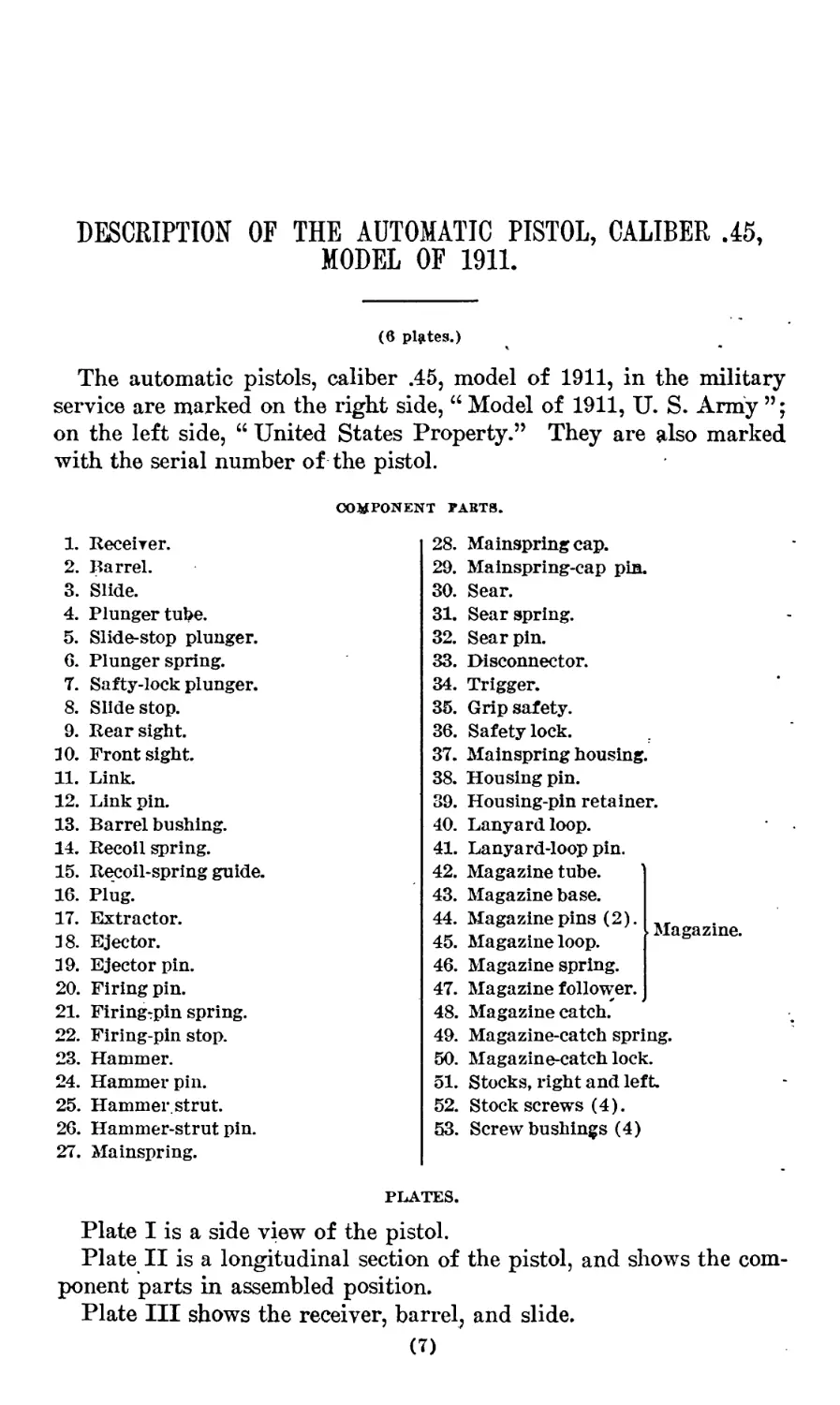
DESCRIPTION OF THE AUTOMATIC PISTOL, CALIBER .45,
MODEL OF 1911.
(6 plates.)
The automatic pistols, caliber .45, model of 1911, in the military
service are marked on the right side, “ Model of 1911, U. S. Army
on the left side, “ United States Property.” They are also marked
with the serial number of the pistol.
COMPONENT PARTS.
1. Receiver.
2. Barrel.
3. Slide.
4. Plunger tube.
5. Slide-stop plunger.
6. Plunger spring.
7. Safty-lock plunger.
8. Slide stop.
9. Rear sight.
10. Front sight.
11. Link.
12. Link pin.
13. Barrel bushing.
14. Recoil spring.
15. Recoil-spring guide.
16. Plug.
17. Extractor.
18. Ejector.
19. Ejectorpin.
20. Firing pin.
21. Firing^pin spring.
22. Firing-pin stop.
23. Hammer.
24. Hammer pin.
25. Hammer, strut.
26. Hammer-strut pin.
27. Mainspring.
28.
29.
30.
31.
32.
33.
34.
35.
36.
37.
38.
39.
40.
41.
42.
43.
44.
45.
46.
47.
48.
49.
50.
51.
52.
53.
Mainspring cap.
Mainspring-cap pin.
Sear.
Sear spring.
Sear pin.
Disconnector.
Trigger.
Grip safety.
Safety lock.
Mainspring housing.
Housing pin.
Housing-pin retainer.
Lanyard loop.
Lanyard-loop pin.
Magazine tube.
Magazine base.
Magazine pins (2).
Magazine loop.
Magazine spring.
Magazine follower.
Magazine catch.
Magazine-catch spring.
Magazine-catch lock.
Stocks, right and left
Stock screws (4).
Screw bushings (4)
Magazine.
PLATES.
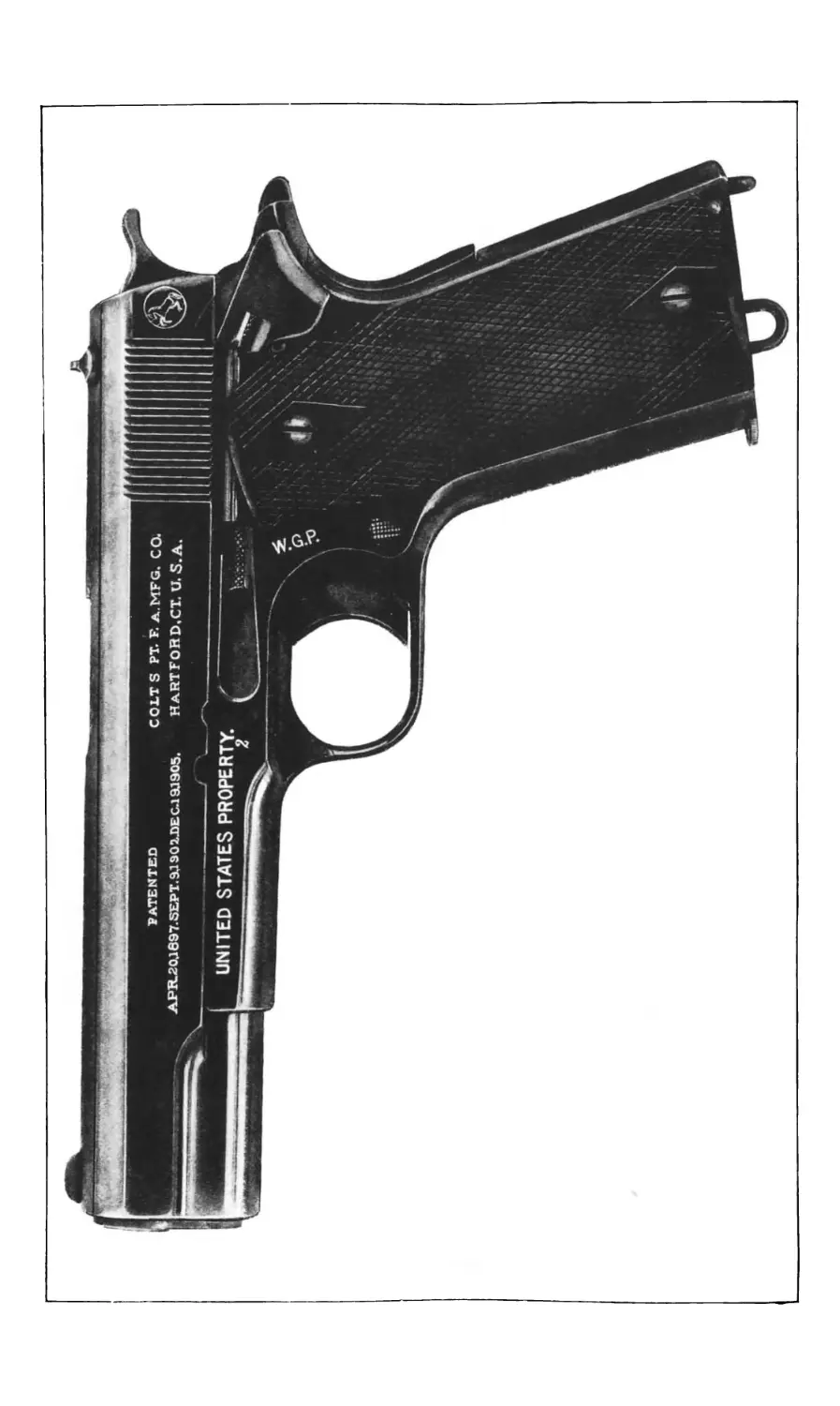
Plate I is a side view of the pistol.
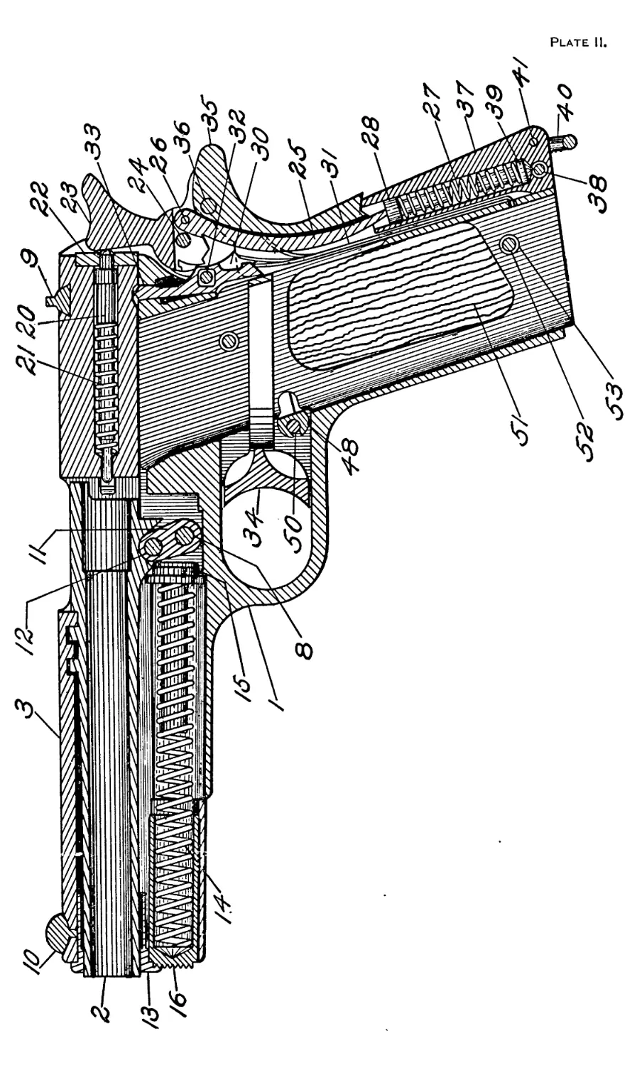
Plate II is a longitudinal section of the pistol, and shows the com-
ponent parts in assembled position.
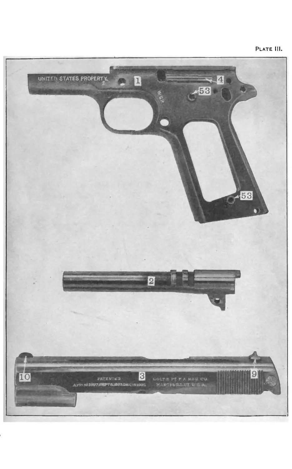
Plate III shows the receiver, barrel, and slide.
(?)
' 8
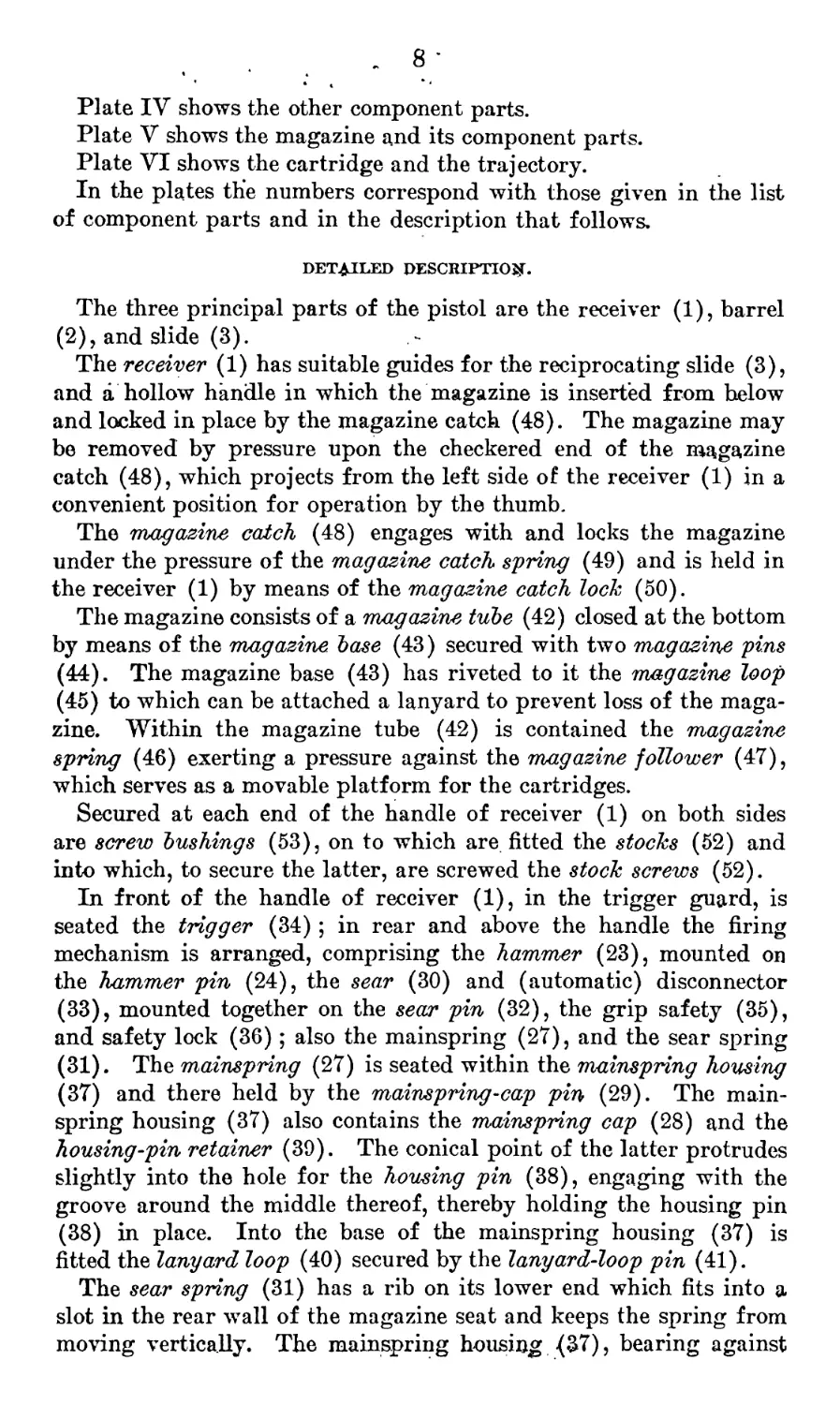
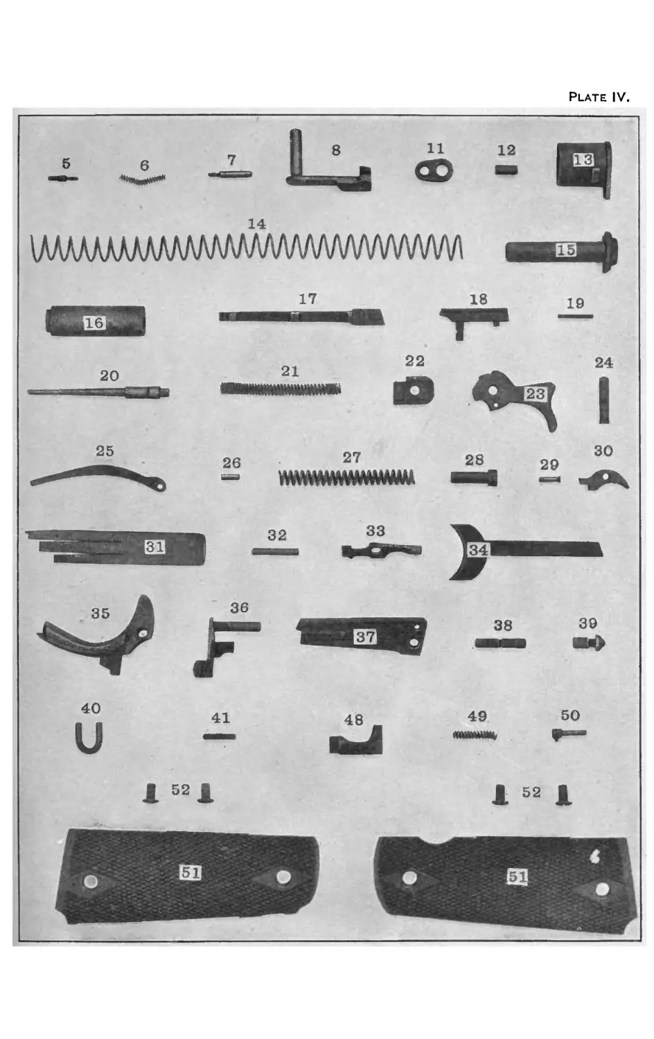
Plate IV shows the other component parts.
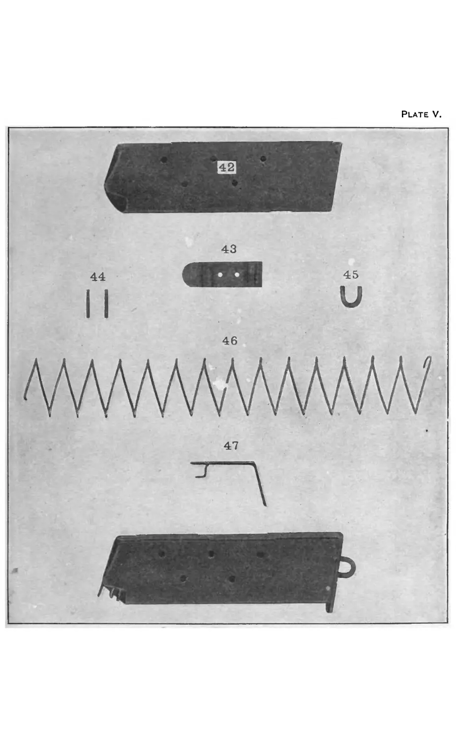
Plate V shows the magazine and its component parts.
Plate VI shows the cartridge and the trajectory.
In the plates the numbers correspond with those given in the list
of component parts and in the description that follows.
DETAILED DESCRIPTION.
The three principal parts of the pistol are the receiver (1), barrel
(2), and slide (3).
The receiver (1) has suitable guides for the reciprocating slide (3),
and a hollow handle in which the magazine is inserted from below
and locked in place by the magazine catch (48). The magazine may
be removed by pressure upon the checkered end of the magazine
catch (48), which projects from the left side of the receiver (1) in a
convenient position for operation by the thumb.
The magazine catch (48) engages with and locks the magazine
under the pressure of the magazine catch spring (49) and is held in
the receiver (1) by means of the magazine catch lock (50).
The magazine consists of a magazine tube (42) closed at the bottom
by means of the magazine base (43) secured with two magazine pins
(44). The magazine base (43) has riveted to it the magazine loop
(45) to which can be attached a lanyard to prevent loss of the maga-
zine. Within the magazine tube (42) is contained the magazine
spring (46) exerting a pressure against the magazine follower (47),
which serves as a movable platform for the cartridges.
Secured at each end of the handle of receiver (1) on both sides
are screw bushings (53), on to which are fitted the stocks (52) and
into which, to secure the latter, are screwed the stock screws (52).
In front of the handle of receiver (1), in the trigger guard, is
seated the trigger (34) ; in rear and above the handle the firing
mechanism is arranged, comprising the hammer (23), mounted on
the hammer pin (24), the sear (30) and (automatic) disconnector
(33), mounted together on the sear pin (32), the grip safety (35),
and safety lock (36); also the mainspring (27), and the sear spring
(31). The mainspring (27) is seated within the mainspring housing
(37) and there held by the mainspring-cap pin (29). The main-
spring housing (37) also contains the mainspring cap (28) and the
housing-pin retainer (39). The conical point of the latter protrudes
slightly into the hole for the housing pin (38), engaging with the
groove around the middle thereof, thereby holding the housing pin
(38) in place. Into the base of the mainspring housing (37) is
fitted the lanyard loop (40) secured by the lanyard-loop pin (41).
The sear spring (31) has a rib on its lower end which fits into a
slot in the rear wall of the magazine seat and keeps the spring from
moving vertically. The mainspring housing (37), bearing against
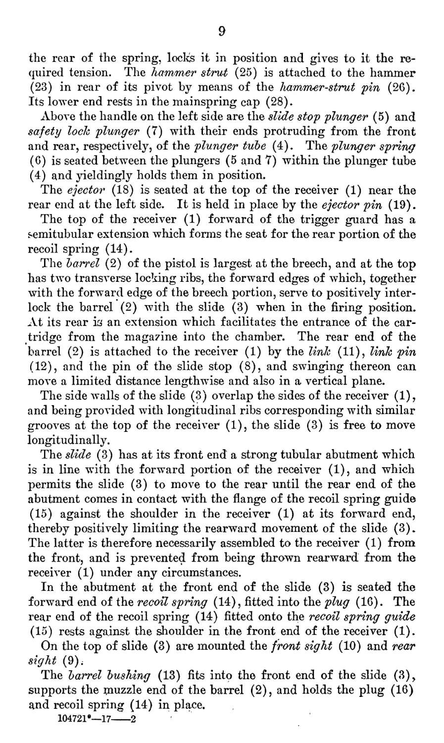
9
the rear of the spring, locks it in position and gives to it the re-
quired tension. The hammer strut (25) is attached to the hammer
(23) in rear of its pivot by means of the hammer-strut pin (26).
Its lower end rests in the mainspring cap (28).
Above the handle on the left side are the slide stop plunger (5) and
safety lock plunger (7) with their ends protruding from the front
and rear, respectively, of the plunger tube (4). The plunger spring
(6) is seated between the plungers (5 and 7) within the plunger tube
(4) and yieldingly holds them in position.
The ejector (18) is seated at the top of the receiver (1) near the
rear end at the left side. It is held in place by the ejector pin (19).
The top of the receiver (1) forward of the trigger guard has a
semitubular extension which forms the seat for the rear portion of the
recoil spring (14).
The barrel (2) of the pistol is largest at the breech, and at the top
has two transverse locking ribs, the forward edges of which, together
with the forward edge of the breech portion, serve to positively inter-
lock the barrel (2) with the slide (3) when in the firing position.
At its rear is an extension which facilitates the entrance of the car-
tridge from the magazine into the chamber. The rear end of the
barrel (2) is attached to the receiver (1) by the link (11), link pin
(12), and the pin of the slide stop (8), and swinging thereon can
move a limited distance lengthwise and also in a vertical plane.
The side walls of the slide (3) overlap the sides of the receiver (1),
and being provided with longitudinal ribs corresponding with similar
grooves at the top of the receiver (1), the slide (3) is free to move
longitudinally.
The slide (3) has at its front end a strong tubular abutment which
is in line with the forward portion of the receiver (1), and which
permits the slide (3) to move to the rear until the rear end of the
abutment comes in contact with, the flange of the recoil spring guide
(15) against the shoulder in the receiver (1) at its forward end,
thereby positively limiting the rearward movement of the slide (3).
The latter is therefore necessarily assembled to the receiver (1) from
the front, and is prevented from being thrown rearward from the
receiver (1) under any circumstances.
In the abutment at the front end of the slide (3) is seated the
forward end of the recoil spring (14), fitted into the plug (16). The
rear end of the recoil spring (14) fitted onto the recoil spring guide
(15) rests against the shoulder in the front end of the receiver (1).
On the top of slide (3) are mounted the front sight (10) and rear
sight (9);
The barrel bushing (13) fits into the front end of the slide (3),
supports the muzzle end of the barrel (2), and holds the plug (16)
and recoil spring (14) in place.
104721е—17--2
10
When the slide (3) and the barrel (2) therein are mounted upon
the receiver (1) and the slide stop (8) is in its place, so that the pin
part of the slide stop (8) locks the barrel (2) to the receiver (1)
through the link (11), the slide (3) is thereby positively locked in
place upon the receiver (1).
The firing pin (20), firing-pin spring (21), and (shell) extractor
(17) are carried in the rear end of the slide (3) and locked by the
firing-pin stop (22). By pressing the firing pin (20) forward so as
to clear the firing-pin stop (22), the latter is released and may be
removed downwardly, leaving both firing pin (20) and extractor
(17) free for removal.
The slide stop (8) consists of the pin part, which serves as a pivot
and passes through the link (11), and a body, on which is a thumb
piece, for releasing the slide (3) from the open position.
Thd safety lock (36) consists of a thin plate, a projecting pin, a
thumb piece, and a projecting stud. The pin part serves as a pivot
for the safety lock (36) and is at the same time a pivot for the grip
safety (35). The upper corner of the plate has an angle which will
fit into a correspondingly shaped recess in the slide (3). When the
slide (3) is in its forward position, and the hammer (23) is full*
cocked, the safety lock (36) may be pushed up manually, by means of
the thumb piece, thereby positively locking the hammer and the slide.
While the safety lock (36) is being pushed up into the locking posi-
tion the stud on the safety lock (36) is being carried upward and it
finally stands in rear of the lower arm of the sear (30), blocking the
sear (30) and causing the locking of the hammer (23). If the safety
lock (36) is pressed down so as to release the slide (3) the projecting
stud on the safety lock (36) clears the sear (30), permitting the sear
(30) to be operated by the trigger (34), thereby causing the release
of the hammer (23) if the grip safety (35) is pressed inward, as by
the hand'grasping the handle of the pistol, and the trigger (34) is
pulled.
The grip safety (35) is pivoted in the upper part of the receiver
(1). Its lower part projects from the rear face of the handle under
pressure of the short leaf of the sear spring (31), thereby locking the
trigger whenever the handle of the pistol is released. But when the
handle is grasped, as in the firing position, the grip safety (35) re-
leases the trigger (34) without requiring the attention or thought of
the firer.
The (automatic) disconnector (33) is mounted in the receiver (1)
in rear of the magazine seat. In the underside of the slide (3) and
near its rear end, a recess is provided which stands above the top of
the disconnector (33) when the slide (3) is in the forward firing
position. With the slide in this position the disconnector (33) is
raised to its operative position by the center leaf of the sear spring
11
(31) and it then will transmit the movement of the trigger (34) to
the sear (30). The forward surfaces of the recess of the slide (3)
and of the projecting end of the disconnector (33) are inclining, so
that the rearward movement of the slide (3) depresses the connector
(33) until the slide (3) again returns to its forward position. In this
depressed position of the disconnector (33) the trigger (34) is dis-
connected from the sear (30), allowing the sear (30) to reengage the
hammer (23). This arrangement automatically and positively pre-
vents firing of the pistol except when all its parts are in the fully
closed and locked firing position, and it also prevents more than one
shot from following each pull of the trigger (34).
TO DISMOUNT AND ASSEMBLE THE PISTOL.
Remove the magazine by pressing the magazine catch (48).
Press the plug (16) inward and turn the barrel bushing (13) to
the right until the plug (16) and the end of the recoil spring (14)
protrude from their seat, releasing the tension of the spring (14).
As the plug (16) is allowed to protrude from its seat, the finger or
thumb should be kept over it, so that it will not jump away and be
lost or strike the operator. Draw the slide (3) rearward until the
smaller rear recess in its lower left edge stands above the projec-
tion on the thumb piece of the slide stop (8); press gently against
the end of the pin of the slide stop (8) which protrudes from the
right side of the receiver (1) above the trigger guard and remove
the slide stop (8).
This releases the link (11), allowing the barrel (2), with the link
(11) and the slide (3), to be drawn forward together from the
receiver (1), carrying with them the barrel bushing (13)^ recoil
spring (14), plug (16), and recoil-spring guide (15).
Remove these parts from the slide (3) by withdrawing the recoil-
spring guide (15) from the rear of the recoil spring (14), and draw-
ing the plug (16) and the recoil spring (14) forward from the slide
(3). Turn plug (16) to right to remove from recoil spring (14).
Turn the barrel bushing (13) to the left until it may be drawn for-
ward from the slide (3). This releases the barrel (2) which, with
the link (11), may be drawn forward from the slide (3), and by
pushing out the link pin (12) the link (11) is released from the
barrel (2).
Press the rear end of the firing pin (20) forward until it clears the
firing-pin stop (22), which is then drawn downward from its seat in
the slide (3); the firing pin (20), firing-pin spring (21), and ex-
tractor (17) are then removed from the rear of the slide (3).
The safety lock (36) is readily withdrawn from the receiver (1)
by cocking the hammer (23) and pushing from the right on the pin
part or pulling outward on the thumb piece of the safety lock (36)
12
when it is midway between its upper and lower positions. The
cocked hammer (23) is then lowered and removed after removing the
hammer pin (24) from the left side of the receiver (1). The housing
pin (38) is then pushed out from the right side of the receiver (1),
which allows the mainspring housing (37) to be withdrawn down-
ward and the grip safety (35) rearward from the handle. The sear
spring (31) may then be removed. By pushing out the sear pin (32)
from the right to the left side of the receiver (1), the sear (30) and
the disconnector (33) are released.
To remove the mainspring (27), mainspring cap (28), and hous-
ing-pin retainer (39) from the mainspring housing (37), compress
the mainspring (27) and push out the small mainspring cap pin (29).
To remove the magazine catch (48) from the receiver (1), its
checkered left end must be pressed inward, when the right end of the
magazine catch (48) will project so far from the right side of the
receiver (1) that it may be rotated one-half turn. This movement
will release the magazine catch lock (50) from its seat in the receiver
(1), when the magazine catch (48), the magazine catch lock (50), and
the magazine catch spring (49) may be removed.
With the improved design of magazine catch lock (50) the opera-
tion of dismounting the magazine catch (48) is simplified in that
when the magazine catch (48) has been .pressed inward the magazine
catch lock4(50) is turned by means of a screw driver or the short leaf
of the sear spring (31) a quarter turn to the left when the magazine
catch (48) with its contents can be removed. The improved design
will be recognized from the fact that the head of the magazine catch
lock (50) is slotted.
The trigger (34) can then be removed rearwardly from the re-
ceiver (1).
The hammer strut (25) or the long arm of the screw driver can
can be used to push out all the pins except the mainspring-cap pin
(29) lanyard-loop pin (41), and ejectorpin (19).
To assemble the pistol, proceed in the reverse order.
It should be noted that the disconnector (33) and sear (30) are
assembled as follows: Place the cylindrical part of the disconnector
(33) in its hole in the receiver (1) with the flat face of the lower
part of the disconnector (33) resting against the yoke of the trigger
(34). Then place the sear (30), lugs downward, so that it strad-
dles the disconnector (33). The sear pin (32) is then inserted in
place, so that it passes through both the disconnector (33) and the
sear (30).
The sear (30), disconnector (33), and hammer (23) being in place
and the hammer (23) down, to replace the sear spring (31), locate
its lower end in the cut in the receiver (1), with the end of the long
leaf resting on the sear (30); then insert the mainspring housing (37)
13
until its lower end projects below the frame about one-eighth of an
inch, replace the grip safety (35), cock the hammer (23), and replace
the safety lock (36) ; then lower the cocked hammer (23), push the
mainspring housing (37) home and insert the housing pin (38).
In assembling the safety lock (36). to the receiver (1) use the tip
of the magazine follower (47) or the screw driver to press the safety-
lock plunger (7) home, thus allowing the seating of the safety lock
(36). It should be remembered that when assembling the safety
lock (36) the hammer (23) must be cocked.
When replacing the slide (3) and barrel (2) on the receiver (1),
care must be taken that the link (11) is tilted forward as far as pos-
sible and that the link pin (12) is in place.
METHOD OF OPERATION.
A loaded magazine is placed in the handle and the slide (3) drawn
fully back and released, thus bringing the first cartridge into the
chamber (if the slide is open, push down the slide stop (8) to let the
slide (3) go forward). The hammer (23) is thus cocked and the
pistol is ready for firing.
If it is desired to make the pistol ready for instant use and for
firing with the least possible delay the maximum number of shots,
draw back the slide (3), insert a cartridge by hand into the cham-
ber of the barrel (2), allow the slide (3) to close, then lock the slide
(3) and the cocked hammer (23) by pressing the safety lock (36)
upward, and insert a loaded magazine. The slide (3) and hammer
(23) being thus positively locked, the pistol may be carried safely at
full cock, and it is only necessary to press down the safety lock (36)
(which is located within easy reach of the thumb) when raising the
pistol to the firing position.
The grip safety (35) is provided with an extending horn, which
not only serves as a guard to prevent the hand of the shooter from
slipping upward and being struck or injured by the hammer (23),
but also aids in accurate shooting by keeping the hand in the same
position for each shot; and, furthermore, permits the lowering pf the
cocked hammer (23) with one hand by automatically pressing in the
grip safety (35) when the hammer (23) is drawn slightly beyond the
cocked position. In order to release the hammer (23), the grip
safety (35) must be pressed in before the trigger (34) is pulled.
SAFETY DEVICES.
It is impossible for the firing pin (20) to discharge or even touch
the primer, except on receiving the full blow of the hammer (23).
The pistol is provided with two automatic safety devices:
(1) The (automatic) disconnector (33) which positively prevents
the release of the hammer (23) unless the slide . (3) and barrel (2)
14
are in the forward position and safely interlocked; this device also
controls the firing and prevents more than one shot from following
each pull of the trigger (34).
(2) The (automatic) grip safety (35) at all times locks the trigger
(34) unless the handle is firmly grasped and the grip safety (35)
pressed in.
The pistol is in addition provided with a safety lock (36) by which
the closed slide (3) and the cocked hammer (23) can be at will posi-
tively-locked in position.
OPERATION IN DETAIL.
The magazine may be charged with any number of cartridges from
one to seven.
The charged magazine is inserted in the handle and the slide
(3) drawn once to the rear. This movement cocks the hammer (23),
compresses the recoil spring (14), and, when the slide (3) reaches the
rear position, the magazine follower (47) raises the upper cartridge
into the path of the slide (3). The slide (3) is then released and, be-
ing forced forward by the recoil spring (14), carries the first cartridge
into the chamber of the barrel (2). As the slide (3) approaches its
forward position, it encounters the rear extension of the barrel (2)
and forces the barrel forward; the rear end of the barrel (2) swings
upward on the link (11), turning on the muzzle end as on a fulcrum.
When the slide (3) and barrel (2) reach their forward position they
are positively locked together by the locking ribs on the barrel (2)
and their joint forward movement is arrested by the barrel lug
encountering the pin on the slide stop (8).
The pistol is then ready for firing.
When the hammer (23) is cocked, the hammer strut (25) moves
downward, compressing the mainspring-(27), and the sear *(30),
under action of the long leaf of the sear spring (31), engages its nose
in the notch on the hammer (23).
In order that the pistol may be fired the following conditions
must exist: The grip safety (35) must be pressed in, leaving the
trigger (34) free to move; the slide (3) must be in its forward posi-
tion, properly interlocked with the barrel (2), so that the disconnector
(33) is held in the recess on the underside of the slide (3) under the
action of the sear spring (31), transmitting in this position any
motion of the trigger (34) to the sear (30); the safety lock (36) must
be down, in the unlocked position, so that the sear (30) will be
unblocked and free to release the hammer (23) and the slide will be
free to move back.
On pulling the trigger (34), the sear (30) is moved and the released
hammer (23) strikes the firing pin (20) which transmits the blow to
the primer of the cartridge. The pressure of the gases generated in
15
the barrel (2), by the explosion, of the powder in the cartridge, is
exerted in a forward direction against the bullet, driving it through
the bore, and in a rearward direction against the face of the slide (3),
driving the latter and the barrel (2) to the rear together. The
downward swinging movement of the barrel (2) unlocks it from the
slide (3), and the barrel (2) is then stopped in its lowest position.
The slide (3) continues to move to the rear, opening the breech,
cocking .the hammer (23), extracting and ejecting the empty shell and
compressing the recoil spring (14), until it—the slide (3)—reaches its
rearmost position when another cartridge is raised in front of it and
forced into the chamber bf the barrel (2) by the return movement of
the slide (3) under pressure of the recoil spring (14).
The weight and consequently the inertia of the slide (3), aug-
mented by those of the barrel (2) are so many times greater than the
weight and inertia of the bullet that the latter has been given its
maximum velocity and has been driven from the muzzle of the bar-
rel (2) before the slide (3) and barrel (2) have recoiled to the point
where the barrel (2) commences its unlocking movement. This con-
struction, therefore, delays the opening of the breech of the barrel
(2) until after the bullet has left the muzzle and therefore practically
prevents the escape of any of the powder gases to the rear after the
breech has been opened.
This factor of safety is further increased by the tension of the
recoil spring (14) and mainspring (27), both of which oppose the
rearward movement of the slide (3).
While the comparatively great weight of the slide (3) of this pis-
tol insures safety against premature opening of the breech, it also
insures operation of the pistol, because at the point of the rearward
opening movement where the barrel (2) is unlocked and stopped,
the heavy slide (3) has attained a momentum which is sufficient to
carry it through its complete opening movement and makes the
pistol ready for another shot.
When the magazine has been emptied, the pawl-shaped slide stop
(8) will be raised by the magazine follower (47) under action of the
magazine spring (46) into the front recess on the lower left side of
the slide (3), thereby locking the slide (3) in the open position, and
serving as an indicator to remind the shooter that the empty maga-
zine must be replaced by a charged one before the firing can be
continued.
Pressure upon the magazine catch (48) quickly releases the empty
magazine from the handle and permits the insertion of a loaded
magazine.
To release the slide (3) from the open position, it is only necessary
to press upon the thumb piece of the slide stop (8) when the slide
(3) will go forward to its closed position, carrying a cartridge from
16
the previously inserted magazine into the barrel (2) and making the
pistol ready for firing again.
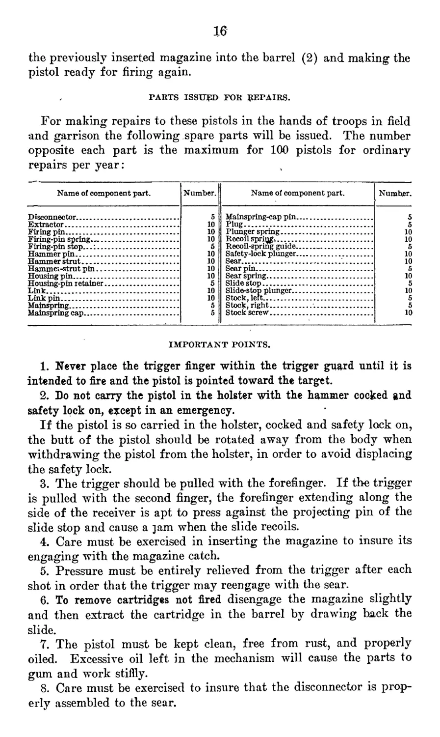
PARTS ISSUED FOR REPAIRS.
For making repairs to these pistols in the hands of troops in field
and garrison the following spare parts will be issued. The number
opposite each part is the maximum for 100 pistols for ordinary
repairs per year:
Name of component part.
Number.
Name of component part.
Number.
Disconnector........................
Extractor...........................
Firing pin..........................
Firing-pin spring*--................
Firing-pin stop.....................
Hammer pin..........................
Hammer strut.................
Hammei-strut pin....................
Housing pin.........................
Housing-pin retainer................
Link................................
Link pin............................
Mainspring..........................
Mainspring cap......................
5
10
10
10
5
10
10
10
10
5
10
10
5
5
Mainspring-cap pin.....................
Plug..................................
Plunger spring........................
Recoil spri^...........................
Recoil-spring guide....................
Safety-lock plunger...................
Sear...................................
Sear pin...............................
Sear spring...........,................
Slide stop.............................
Slide-stop plunger.....................
Stock, left............................
Stock, right.........•.................
Stock screw............................
5
5
10
10
5
10
10
5
10
5
10
5
5
10
IMPORTANT POINTS.
1. Never place the trigger finger within the trigger guard until it is
intended to fire and the pistol is pointed toward the target.
2. Do not carry the pistol in the holster with the hammer cocked and
safety lock on, except in an emergency.
If the pistol is so carried in the holster, cocked and safety lock on,
the butt of the pistol should be rotated away from the body when
withdrawing the pistol from the holster, in order to avoid displacing
the safety lock.
3. The trigger should be pulled with the forefinger. If the trigger
is pulled with the second finger, the forefinger extending along the
side of the receiver is apt to press against the projecting pin of the
slide stop and cause a jam when the slide recoils.
4. Care must be exercised in inserting the magazine to insure its
engaging with the magazine catch.
5. Pressure must be entirely relieved from the trigger after each
shot in order that the trigger may reengage with the sear.
6. To remove cartridges not fired disengage the magazine slightly
and then extract the cartridge in the barrel by drawing back the
slide.
7. The pistol must be kept clean, free from rust, and properly
oiled. Excessive oil left in the mechanism will cause the parts to
gum and work stiffly.
8. Care must be exercised to insure that the disconnector is prop-
erly assembled to the sear.
17
9. ’ The hammer should not be snapped when the pistol is partially
disassembled.
10. The stocks need never be removed, as the pistol can be dis-
mounted and assembled without removing them.
11. Use no hammer either in assembling or dismounting the pistol.
12. Magazine: Reasonable care should be taken to see that the
magazine is not dented or otherwise damaged.
Never insert the magazine and strike it smartly with the hand to
force it home, as this may spring the base or the inturning lips at
the top. It should be inserted by a quick continuous movement.
CLEANING KIT.
For cleaning, dismounting, and assembling the pistol a kit is issued
consisting of a metal box containing the following articles:
10 screw drivers.
10 cleaning rods, brass (made so that either a cloth wiper or bristle
brush can be used).
10 thong brushes.
1 oil can.
1 grease pot for cosmic.
The above articles, with the exception of the oil can and grease
pot for cosmic, are also supplied as part of the contents of the arm
repair chest, model of 1910, when this chest is issued to organizations
equipped with the pistol. The cleaning kit will therefore be issued
only to organizations equipped with the pistol and not provided with
an arm repair chest.
MISCELLANEOUS DATA CONCERNING PISTOL.
Weight, 2 pounds 7 ounces.
Trigger pull, 6 to 7| pounds.
Total length, 8.593 inches.
Barrel:
Length, 5.025 inches.
Diameter of bore, 0.445 inch.
Rifling:
Grooves—
Number, 6.
Width, 0.1522 inch.
Depth, 0.003 inch.
Lands, width, 0.072 inch.
Twist, one turn in 16 inches, left-handed.
Front sight above axis of bore, 0.5597 inch.
18
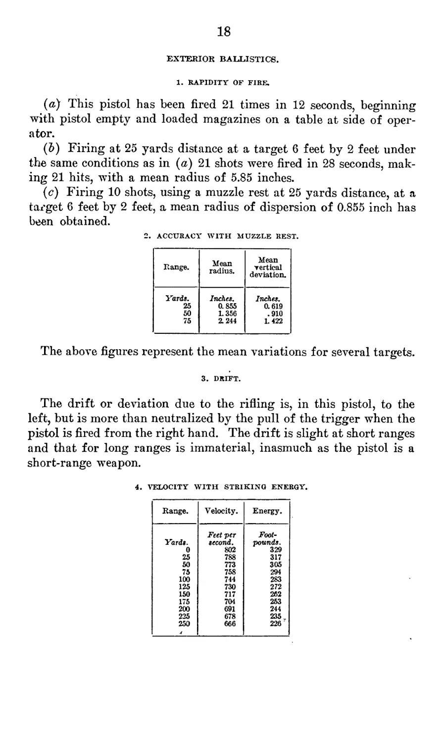
EXTERIOR BALLISTICS.
1. RAPIDITY OF FIRE.
(a) This pistol has been fired 21 times in 12 seconds, beginning
with pistol empty and loaded magazines on a table at side of oper-
ator.
(&) Firing at 25 yards distance at a target 6 feet by 2 feet under
the same conditions as in (a) 21 shots were fired in 28 seconds, mak-
ing 21 hits, with a mean radius of 5.85 inches.
(<?) Firing 10 shots, using a muzzle rest at 25 yards distance, at a
tai'get 6 feet by 2 feet, a mean radius of dispersion of 0.855 inch has
been obtained.
2. ACCURACY WITH MUZZLE REST.
Range. Mean radius. Mean vertical deviation.
Yards, Inches. Inches.
25 0.855 0.619
50 1.356 .910
75 2.244 1. 422
The above figures represent the mean variations for several targets.
3. DRIFT.
The drift or deviation due to the rifling is, in this pistol, to the
left, but is more than neutralized by the pull of the trigger when the
pistol is fired from the right hand. The drift is slight at short ranges
and that for long ranges is immaterial, inasmuch as the pistol is a
short-range weapon.
4. VELOCITY WITH STRIKING ENERGY.
Range. Velocity. Energy.
Yards. 0 25 50 75 100 125 150 175 200 225 250 I Feet per second. 802 788 773 758 744 730 717 704 691 678 666 Foot- pounds. 329 317 305 294 283 272 262 253 244 235 u 226
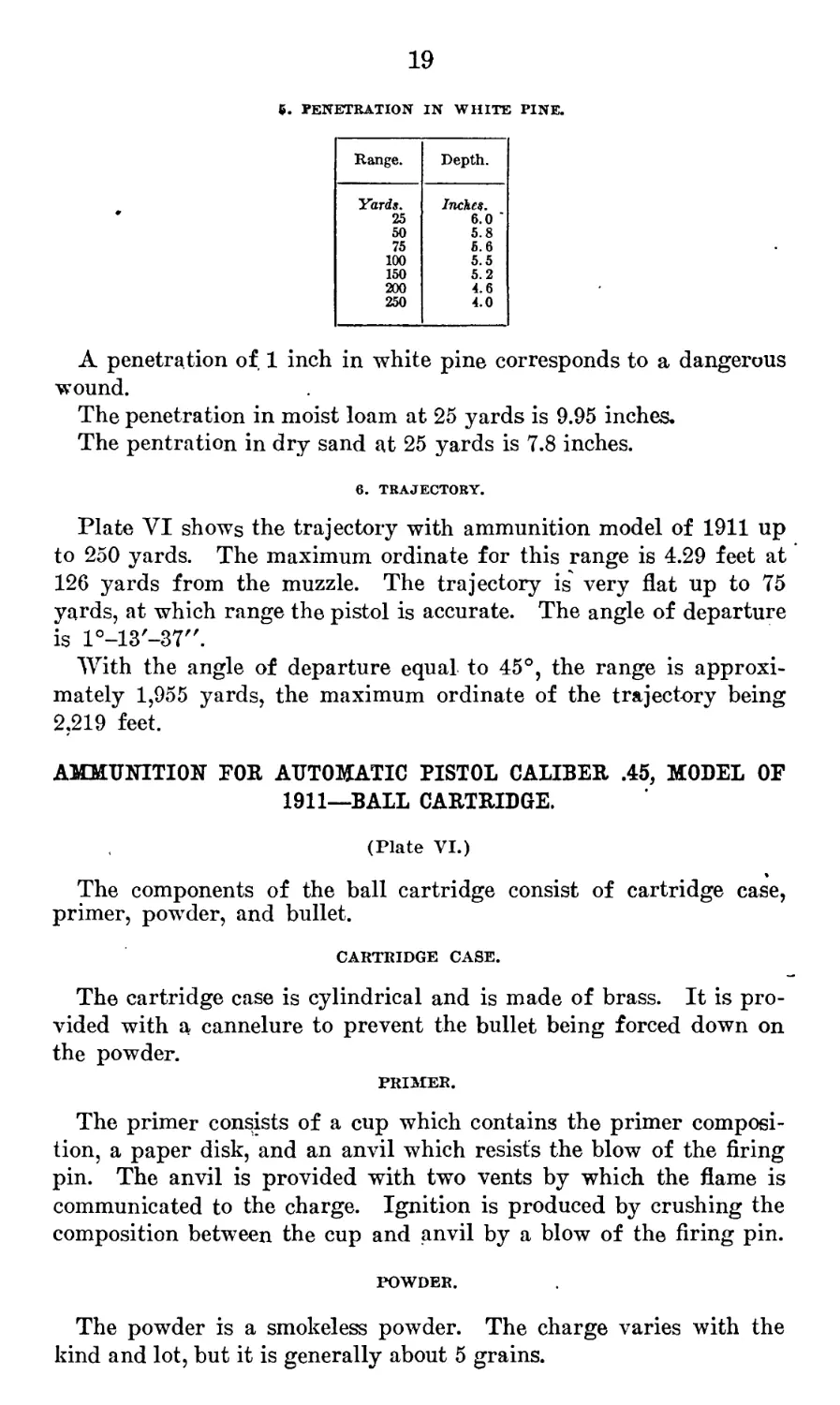
19
6. penetration in white pine.
Range. Depth.
Yards, 25 50 75 100 150 200 250 Inches. 6.0 ’ 5.8 fi.6 5.5 5.2 4.6 4.0
A penetration of 1 inch in white pine corresponds to a dangerous
wound.
The penetration in moist loam at 25 yards is 9.95 inches.
The pentration in dry sand at 25 yards is 7.8 inches.
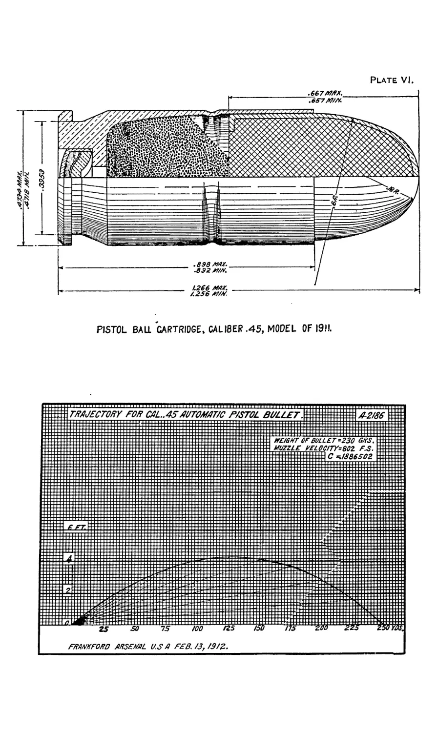
6. TRAJECTORY.
Plate VI shows the trajectory with ammunition model of 1911 up
to 250 yards. The maximum ordinate for this range is 4.29 feet at
126 yards from the muzzle. The trajectory is very flat up to 75
yards, at which range the pistol is accurate. The angle of departure
is l°-13'-37".
With the angle of departure equal to 45°, the range is approxi-
mately 1,955 yards, the maximum ordinate of the trajectory being
2,219 feet.
AMMUNITION FOR AUTOMATIC PISTOL CALIBER .45, MODEL OF
1911—BALL CARTRIDGE.
(Plate VI.)
The components of the ball cartridge consist of cartridge case,
primer, powder, and bullet.
CARTRIDGE CASE.
The cartridge case is cylindrical and is made of brass. It is pro-
vided with a cannelure to prevent the bullet being forced down on
the powder.
PRIMER.
The primer consists of a cup which contains the primer composi-
tion, a paper disk, and an anvil which resists the blow of the firing
pin. The anvil is provided with two vents by which the flame is
communicated to the charge. Ignition is produced by crushing the
composition between the cup and anvil by a blow of the firing pin.
POWDER.
The powder is a smokeless powder. The charge varies with the
kind and lot, but it is generally about 5 grains.
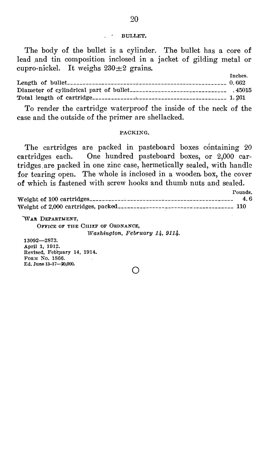
20
. BULLET.
The body of the bullet is a cylinder. The bullet has a core of
lead .and tin composition inclosed in a jacket of gilding metal or
cupro-nickel. It weighs 230±2 grains.
Inches.
Length of bullet______________________j.---------------------------0.662
Diameter of cylindrical part of bullet----------------------------- .45015
Total length of cartridge_____________<----------------------------1.261
To render the cartridge waterproof the inside of the neck of the
case and the outside of the primer are shellacked.
PACKING.
The cartridges are packed in pasteboard boxes containing 20
cartridges each. One hundred pasteboard boxes, or 2,000 car-
tridges, are packed in one zinc case, hermetically sealed, with handle
for tearing open. The whole is inclosed in a wooden box, the cover
of which is fastened with screw hooks and thumb nuts and sealed.
rounds.
Weight of 100 cartridges----------------------------------------------------- 4.6
Weight of 2,000 cartridges, packed-------------------------------------------110
“War Department,
Office of the Chief of Ordnance,
Washington, February Ц, 911%.
13092—2873.
April 1, 1912.
Revised, February 14, 1914.
Form No. 1S66.
Ed. June 13-17—20,000.
Plate III
Plate IV.
Plate V.
Plate VI.
PISTOL BALL CARTRIDGE, CALIBER .45, MODEL OF 19)1.
TRAJECTORY FOR СА/-.Л5AUTOMAT/C P/STOL Bb :i:::~z::z:::::: jf|jj1111 z : zzz z::z ::::::: :z:zz ::: : :::::: j :::::::::z:::::: -II mil = zz: z::z ::::zz: ::::: :z: : :::::: > 'LL£T. EEEE = |::====:|e 42/36 WF/SHT OF BULLET *230 GBS. z::::::! MUZZLE У EL OCJTY-ВйГ F.S. 1llllllllllllffl,?.^fy^.::Ё::::±
25 75 /00 Us Hb F^ANKFO/fD AIF5FMJL U.S Д FSB. /3f /9/2. )/5 ZOd £25 Z5v лДУ,