/
Tags: weapons military affairs patent
Year: 1897
Text
2 Sheets—Sheet 1
(No Model.)
С. H. R. CLAUSIUS.
RECOIL OPERATED FIREARM.
(No Model.)
2 Sheets—Sheet 2.
С. Нм R. CLAUSIUS.
RECOIL OPERATED FIREARM.
No. 593,835.
Patented Nov. 16. 1897.
United States Patent Office.
CLAUS H. R. CLAUSIUS, OF HAMBURG, GERMANY.
RECOIL-OPERATED FIREARM.
SPECIFICATION forming part of Letters Patent No. 693,835, dated November 16,1897.
Applioitlon filed February 5,1880. Serial Ko. 578,116. (Ko model.) Patented in Germany January 29,1895, Ko. 87,663 j ini ;;
Belgium Kovomlwr 15,1886, Ko.118,301 j in England December 31,1885, Ko. 25,042; in Sweden December 31,1885, Koi , ~
7,833; in Italy December 31, 1895, Ko. 40,515 ; in Hungary December 31,1885, Ko. 7)102; in Korway December 31,1895, .
Ke. 4,7281 in Switzerland December 31,1885, Ko. 11,481; in France December 31,1885, Ko. 252,881, and in Austria Feb-
ruary 6,1896, Ko. 46/447. , <
Io all whom it may concern:
Be it known that I,; Claus JI, R. Clausius,
a subject of the German Emperor, and a resi-
dent of Hamburg,in the German Empire,have
5 invented certain new and useful Improve-
ments in Breech-Loading Firearms, (for which
patents have been obtained in the following
countties, to-wit: Germany, Ni>. 87,663,dated
January 29, 1895: Belgium, No, 118,361,
io dated КоуерЛёг 15, 1895; Great Britain,No.
25,042, dated December 31, 1895; Sweden,
No. 7,833, dated December 31, 1895; Italy,
No. 40,515, dated December 31, 1895; Hun-
gary, No. 7,102, dated December 31, 1895;
15 Norway, No, 4,728, dated December 31,1895;
Switzerland, No. 11,481, dated December 31,
1895; France, No. 252,881, dated December
31, 1895, and Austria, No. 40/447, dated Feb-
ruary 6, 1896,) of which the following is a
20 specification.
My present invention relates to improve-
ments in breech-loading firearms, especially
of that class in which the barrel and the
breech-bolt are movably arranged,so that they
25 may recoil together in firing, but may be in-
dependently forced forward again by spring-
power for the purpose of opening or laying
bare the loading-chamber of the breech-frame,
which class of breech-loaders is known as
30 “straight pull-bolt guns.”
The invention comprises a peculiarly-con-
structed breech-closing head arranged be-
tween the breech-bolt and the barrel and
adapted to make a turning and sliding move-
35 ment, which are utilized for coupling or un-
coupling the breech-bolt and the barrel ac-
cordingly; and the object of the improvements
is to secure a reliable closingof the breech by
couplingthe said movable closing-head of the
40 breech-bolt to the barrel and to permit,on the
other hand, an easy and ready uncoupling of
the barrel from the temporarily-retained clos-
ing-head when the said barrel alone is shifted
forward by its spring after the recoil.
45 To render the present invention properly
understood, I will proceed to describe, as an
example, a hand-firearm arranged in accord-
ance with the same, reference being had to
the accompanying drawings, and to letters of
reference marked thereon, which form a part 50
of this specification. . : л
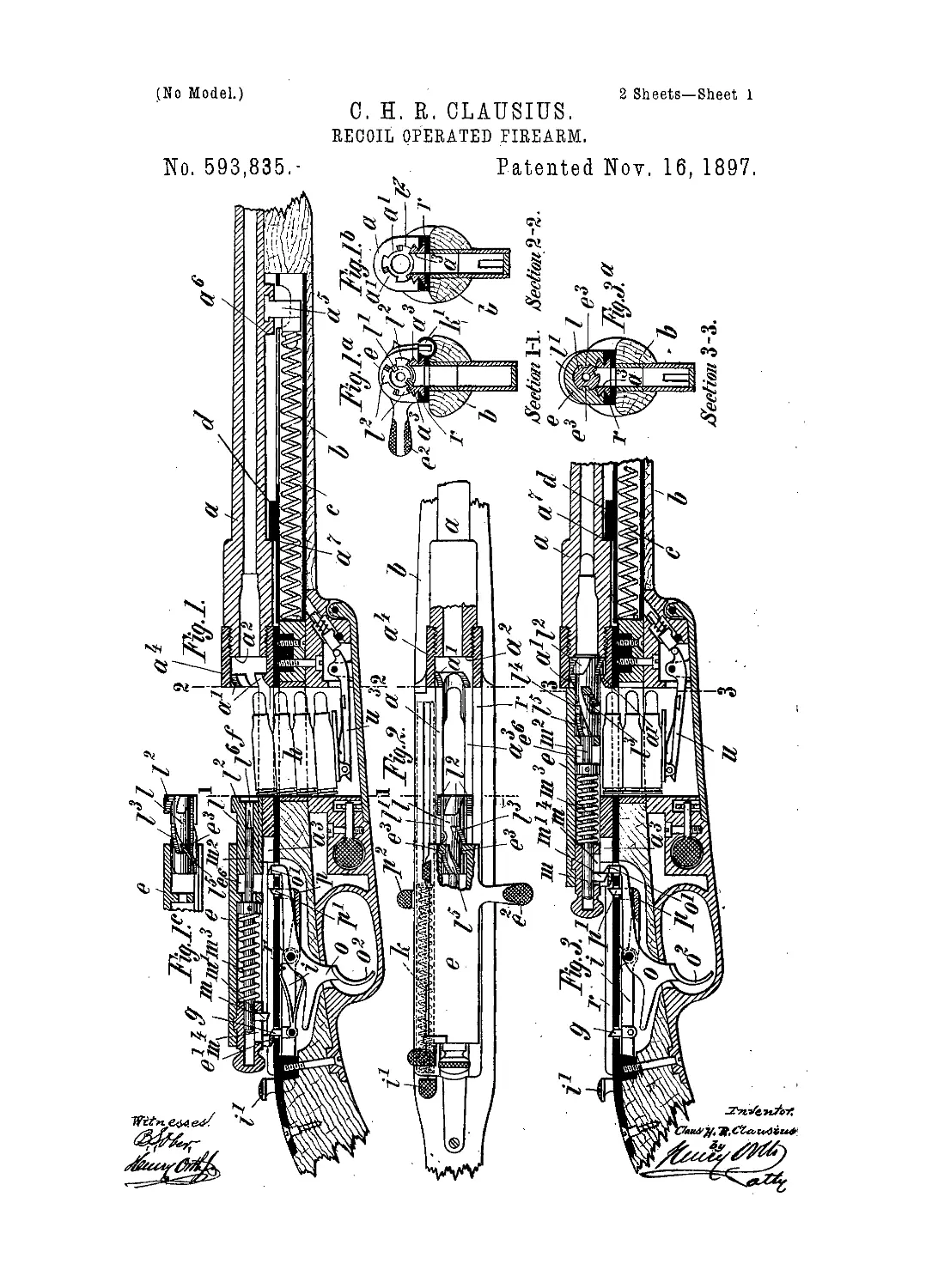
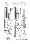
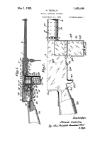
Referring to thedrawings, Figure lisa Ion- n
gitudinal sectional elevation of so much of a /:
breech-loading gun as will be necessary to
illustrate my in vention, the partsbeing shown, 55
in their respective positions after firing., <
Figs. Is and lb are cross-sections on the lines .
1 1 and 2 2 of Fig. 1. Fig. Iе is a detailed
view showing the closing-head in longitudi- .
nal side elevation and illustrating the coop- 60
eration of the same with the breech - bolt./ :
Fig. 2 is a top plan view, partly in section, of..
the improved breech-loading gun shown by
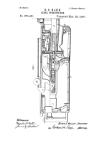
Fig. 1. Fig. 3 is a similar sectional eleva-
tion as Fig. 1, the parts being shown in their 65
respective positions before firing. Fig. 3a is
a cross-section on the line 3 3 of Fig. 3. Fig.':
4 is top plan view of Fig. 3, partly in sec-
tion. Figs. 5 and 6 are views, partly in sec-
tion, illustrating the mode of cooperation of ;o
the breech-bolt, the closing-head, and the
barrel during the forward motion of the lat-
ter in order to uncouple the locked breech-
boltor its movable closing-head, respectively,
from the barrel. Figs. 7 and 8 are detailed 75
views showing the structural features of the
closing - head and the breech - bolt, respec-
tively.
Similar letters refer to si milar parts through-
out the several views. 80
The movable barrel a, arranged in a suit-
able groove of the stock b, is guided in the
usual manner in rings attached to the stock,
the rings being not shown in the drawings.
Upon the rear end of the barrel a is screwed 85
a socket a4, provided on its interior wall with
lugs or projections a'. From the rear end
side or surface of this socket there are ex-
tending two §-shaped slide-rails a3, engag-
ing a dovetail-shaped guide-groove of the 90
breech-frame or breech-plate r, sunk into the
stock b and forming at the same time a part
of the path of the breech-bolt e and its mov-
able closing-head I, as will be described later
on. A recoil-spring c, arranged in a suitable 95
recess of the stock b and acting upon a shoul-
der a5 of the barrel, has tire-tendency to keep .
the barrel in its forward position or to return ' ;
3
5 f 3,835
it thereto. Л stop <7, striking against suit-
able shoulders a1’ a7 of the barrel, is provided
to limit the forward and rearward movements
of the barrel, Fig. 1.
5 The socket-like breech-bolt e, carrying a
handle e3 and adjoining the socket a1 of the
barrel, is adapted tOslideon the breech-frame
?• and on the rearwardly-extendingrailsfi3of
the said socket o'. In order to give the breech-
ib bolt e a reliable guide during its sliding mo-
tion, the breech-bolt is furnished at its lower
front part with two interior grooves e4, en-
gaging or embracing the upper edges of the
S-shaped rails n3. (See Figs. 1’, 3% and 8.)
15' The breech-bolt e contains the firing mech-
anism and the movable closing-head/, which
both will be explained more particularly here-
inafter. A spring It, placed in a recess k' of
the stock or the breech-frame r, respectively,
20 and adapted to act upon a projection es of the
breech:bolt e, tends to keep the said breech-
bolt e in its forward position or to return it
thereto.
. On firing, the breech-bolt e, being coupled
25 to the barrel by means of the movable head
I, which closes the breech of the said barrel,
is recoiled, together with the barrel, by the
action of the gases of explosion. The breech-
bolt e being thus forced to the rear for a suffi-
30 cient extent is caught byastud ornib/y,which
slips in front of a nose e' on the rear end of
the said breech-bolt. Accordingly the latter
is locked in its rear position, while the barrel
a is shifted forward again under the action
35 of the spring c and thereby becomes automat-
ically uncoupled from the breech-bolt e and
its movable head 7, respectively, as hereinaf-
ter more particularly described. Thus be-
tween the barrel and the locked breech-bolt
40 is produced, as clearly shown by Figs. 1 and
2", a free loading-space or loading-chamber f,
into which a cartridge //.may be inserted by
hand or by raising it up through a suitable
slot of the frame r. from a lower magazine by
45 means of any well-known cartridge-elevator
?i. When pressu re is applied to the outwardly-
projecting knob of the lever i, which is mount-
ed in a suitable chamber or recess of the stock
and carries the aforesaid stud or nib g, the
50 latter is depressed in front of the nose e' of
the breech-bolt, so that the same is released
or.unlockcd from the said nibyuiid the breech-
bolt thereby enabled to slide forward under
the action of the lateral spring It. By this
55 forward movement of the breeeh-bolt e the
closing-head 7, carried away with it, is caused
to push the cartridge that has just been in-
serted into 1 he loading-ehambcr/into thb bar-
rel and the cartridge-chamber, respectively,
60 and to couple or connect I he breeeh-bolf e with
tho socket //4 of the said barrel a in a manner
hereinafter described.
The firearm is now loaded and ready for flr-
i ng, for-on the shooting forward of the breech-
65 bolt e a nose m', projecting from the fl ring-pin
m, movably supported in the breech-bolt, will
have struck against the nib o' of the trigger-
lever 0, Fig. 3, and in consequence thereof
the forward end тг of the said firing-pin m is
held back, with the firing-spring m3 in com- 70
pression, to such an extent that it does not
yet enter into the cartridge contained in the
barrel. While the breeeh-bolt e is shooting
forward and pushing the cartridge into the
barrel, the cylindrically-shaped breech-clos- 75
ing head 7, which is movably inserted into a
recess e°, provided in the fore part of breech-
bolt e, and which head has a hole 7° through
it along its axis, projects beyond the forward
end m* of the firing-pin m and prevents the 80
latter from entering the cartridge. During
the last instant of the forward movement only
the firing-pin m and the breech-closing head
I are held back, (the flring-pin by the nib o'
of the trigger-lex er, as already mentioned, St-
and the breech-closing head I in a manner
hereinafter described,) and the breech?boit
moves forward alone to such an extent that
after the disengagement of the trigger-nib o'
from the nose m' of the firing-pin m the latter 90
can be shot forward by the firing-spring ?>i3
in its guide-slot w4 sufficiently to cause tho
point at the forward end in2 of the firing-pin.
m to penetrate into the cartridge in the bar-
rel and to fire the same. Immediately after 95
the firing the barrel and the breech-bolt con-
nected therewith are moved back again by
the backward pressure of the gases, and at
the completion of their recoil movement the
breech-bolt is retained by the aforesaid nib <7, зоо
which engages with the nose e' of the breech-
bolt e, whereupon the barrel is disconnected
and shot forward by the stock-spring c. Tho .
empty cartridge - case has meanwhile been
held back in the loading-chamber (thus 105
opened) by means of an extractor 7' on the
breech-closing head 7, which engages in the
rear annular groove of the cartridge-case, and
maybe ejected from herein the usual manner.
In the space hollowed out-of the stock for no
the trigger-lever о and the lever i, that carries
the stud or nib g, that engages with the nose
e' of the breeeh-bolt, there is also mounted a
third lever p, the upturned and forked for-
ward end or nib p' of which projects into the 115
path of the noso e of the breech-bolt and
passes up behind the said nose when the
breech-bolt is shot forward, in order that the
said breeeh-bolt may not be thrown back
again by the strongly-strained firing-spring 120
in3 so long as the gun is not fired.
During the forward movement of the
breeeh-bolt the noso c' thereof slides over the
inclined top of the forked nib p’, while the
nose 111' of the firing-pin 111 passes, along 125
through tiro groove thereof. In the зато
manner when the breeeh-bolt recoils its nose
e' moves over the inclined top of tho aforesaid
stnd or.nib fit, with which it then engages.
The small lever p is not only provided with .130
the forked nib p‘, but has its arms divided
and pivoted to the pin of the triggeu?lever d
on opposite sides thereof, the forwardly-pro-
jecting arm of said trigger-lever lying and
693,836
3.
having- motion between the branches or
prongs of the forked nibp' of said small lever
p, which is also capable of being depressed in-
dependently of the trigger-lever by meansof a
’ ‘ 5' knob p2,' Fig. 2, that jirojects laterally through
the stock Ъ, so as to cause the grooved nib p'
of the lever jo to release the nose e'of the
:b’i'beeh boli, whereupon the said breech-bolt
-shoots back slightly without the shot being
ro fired. Then the breech-bolt may be drawn
back completely by means of the handle e2
’ on the breech-bolt, the latter or the head I
thereof being thereby unconpled from the
: : ЬагРё1( which remains at rest) and the breech-
15 bolt'being caught by the nib g engaging the
nose e'. Then the eartridge, which has re-
mained undischarged and has been drawn
-• back into the loading space or chamber/by
the extractor Z', may be taken out—that is to
20 say, the gun may thus be unloaded without
firing. In consequence of the shooting back
of the breech-bolt the firing-spring m3 is nn-
; cocked, so that the firearm is thereby secured
against being fired while the breech-bolt is
'25'in this position; but if the shot be fired by
pulling the trigger o2 the trigger-lever 0
- ; pushes downward the lever p with the grooved
nibp', so that this grooved nib is held down
out of the path of the breech-bolt, which is
30 driven back with the barrel, because the
backward pressure of the explosion-gases is
exerted instantaneously and while the finger
of the marksman is still holding down the
trigger-lever o.
35 The forwardly-propelling spring fe of the
breech-bolt and the firing-spring m3 have a
certain peculiar mutual relation during the
last instant of the forward movement of the
breech-bolt. The propelling-spring к iscapa-
40 ble in consequence of the kinetic energy it
has received of stip.compressing the firing-
spring m?, although by that time- the resist-
ance of the firing-spring m3 has become
greater than the pushing force of the pro-
4!> pelling-spring к and fis overcome only with
the aid of the aforesaid energy. Conse-
quently, as already stated, the cocked firing-
spring m3 is able to push back the breech-
j bolt to some extent in opposition to the cocked
50 propelling-spring к after the grooved nib 7;'
! is depressed, in order to enable an inserted
cartridge to be taken out without being fired.
It is, however, not absolutely necessary that
the firing-spring m3 should be more power-
55 ful than the. uncocked propelling-spring k,
because the breech-bolt may also be drawn
back by hand (without having been first
pushed back by the firing-spring) after the
grooved nibp' has been lowered by pressing
60 with the finger upon the corresponding knob
p2. attached to the lever p and projectingout-
’ wardly through the stock. Indeed it is very
desirable that the propelling-spring к of the
breech-bolt and also the stock-spring c of
65 the barrel should be as weak as possible, in
order that powder charges .of very slight
backward pressure and very light projectiles
may be used. Consequently the propelling-
spring к of the breeeh-bolt. should not be
made more powerful than is necessary in 70
view of the described relations between it
and the firing-spring m3.
For the purpose of making the stock-spring
c of the barrel a as weak as possible and of
consequently being able to employ powder 75
charges having a very weak recoil and pro-
jectiles of any desired lightness the lateral
surfaces of the usual projections or locking-
wings к on the breech-closing head Z are not
axially rectilinear, but are in the shape of a 80
helix, which has an equal but opposite pitch
to that of the groove Z3 in the breech-closing
head Z, in which groove P engage pins or shoul-
ders e.3, projecting inwardly from the wall of
the breech-bolt. (See Figs. Iе, 3\ and 8.) 85
The inner pro jections or Ings a' in the rear
socket a* of the barrel a have a pitch similar
to that of the wings Z2, just described. The
helical grooves Z3 in the breech-closing head '
terminate at the rear in a groove Z4, which ex- 90
tends at right angles to the axis of the head
Z and with which there connect the entrance-
grooves Z5 for the aforesaid pins e3 of the
breech-bolt, Figs. 4 and 7.
When the breech-closing head Z, which closes 95
the rear mouth of the barrel, couples together
the, barrel a and the breech-bolt e, as shown
in Figs. 3 and 4, the front end of the said
head Z rests or bears against the rear surface
a2 of the barrel a: The wings Z2 of the breech- too
closing head Z are then in front of the lugs a'
of the socket a4, and the shoulders or pins e3
of the wall of the breech-bolt are in the fore
part of the first-mentioned helical grooves Z8
of the breech-closing head.?. Thuscpnnected 105
the barrel a and the breech-bolt are recoiled .
to a sufficient extent by the backward pres-
sure of the gases for effecting the passage of
the nose e' of the breech-bolt behind the nib
g, whereby the said breeeh-bolt is eaught, as no
already stated above.. The barrel a, which
shoots forward again at once, pulls the breech-
closing head I forward with it, so that there-
by the front helical grooves Z3 of the head I
slide along or over the pins e3 of the breech- 115
bolt. In consequence tjre breech-closing head
I is rotated and its wings I2 turned in front of
the passages between the projections or lugs
a' of the socket a', whereupon these lugs a'
slide forward along the projections or wings 120
I2 of the head Z and rotate them in the same
direction as that in which the breech-closing
head Z is rotated by the helical grooves Z3.
Thus all possibility of jamming between the
barrel or socket <i4, respectively, and the 125
breech-closing headZ is obviated, and the bar-
rel can be projected forward into its firing
position by a weak spring, thereby rendering
possible the use of powder charges having a
small recoil and of light projectiles. 130
As soon as the pins e3 of the brcech-bolt
have entered the perpendicular groove Z4 of
the closing-head Z the latter is held back and
is rotated, still without jamming, only to such
4
БОЗ,835
an extent that two of the wings I2, leaving the
rear mouth or socket a4 of the barrel, rest on
the sliding bars a3, which are extensions of
the socket a4 or its lugs a', respectively, and
5 are guided, as already described, by means
of a dovetail-shaped groove of the framer.
The two opposite wings that lie on the first-
mentioned bars a3 prevent, therefore, the
breech-closing head I from being further ro-
o tated, which, consequently, also in this posi-
tion—that is to say, un rotated and undis-
turbed—will be moved forward again with the
breech-bolt, when, but not until, the latter is
liberated by depressing the nib g. The wings
15 I2 of the breech-closing head Z, moved forward
by the released and returning breech-bolt e,
pass then in between the locking-lugs a' of
the socket a4, and the breech-closing head I,
now rotating, strikes against the rear surface
20 a2 of the barrel a. The head I then remains
stationary in a longitudinal direction and is
only in consequence of the further forward
movement of the breech-bolt and its pin e3
rotated to such an extent that its wings P
25 again pass in front of the locking-lugs a', pro-
vided in the socket a* behind the cartridge-
chamber of the barrel and again couple the
socket a4 or barrel a, respectively. The parts
thus connected and locked cannot be discon-
30 nected by shocks exerted or imparted against
the forward surface of the breech-closing head
I, while on drawingthe barrel from the breech-
bolt, or vice versa, the uncoupling takes place
quite easily.
Having fully described my invention, what 35
I desire to claim and secure by Letters Pat-
tent is—
1. The combination with the endwise-mov-
able barrel provided at its rear end with hel-
ical locking-lugs a', of the breech-bolt e and 40
the closing-head ^provided with a helical
groove of equal but opposite pitch to that of
the lobking-lugs a' on the barrel and with a
peripheral groove Z3 intersecting said helical
groove, said breech-bolt engaging said helical 45
groove of the closing-head, substantially as
and for the purpose set forth..
2. The combination with the breech-bolt
and firing-pin provided with radial lugs e', m',
respectively, and the levers i', p; of the trig- 50
ger-lever 0 and a fulcrnm-pin common to all
three levers, and means for depressing the
upturned nibs or noses thereof independently
of one another, substantially as and for the
purpose set forth. 55
In testimony that I claim the foregoing as
my invention I have signed my name, in pres-
ence of two witnesses, this 17th day of Janu-
ary, 1896.
CLAUS H. R. CLAUSIUS.
Witnesses:
i Alexander Specht, - . ,
'' Max Kacmpff. .