/


Tags: weapons
Year: 1943


Text
CONFIDENTIAL
ORDNANCE PAMPHLET No. 1002
FIRST REVISION
7".2 ROCKET LAUNCHERS, MARK 20,
MARK 22 AND AMMUNITION
DESCRIPTION AND OPERATION
30 NOVEMBER 1943
This publication is CONFIDENTIAL and will be handled in accorda nee
with Article 76z United States Navy Regulations, 1920
NAVY DEPARTMENT
BUREAU OF ORDNANCE
WASHINGTON, D. C.
CONFIDENTIAL
30 November 1943
ORDNANCE PAMPHLET NO. 1002z FIRST REVISION
7".2 ROCKET LAUNCHERS, MARK 20, MARK 22, AND AMMUNITION
1. Ordnance Pamphlet No. 1002, First Revision, describes the operation and use of the
7".2 Rocket Launchers, Mark 20 and Mark 22, the control panels, the equipment, and the ammu-
nition used with these launchers. This pamphlet is made in loose leaf form with the intention
that when new Marks and Mods, of 1".2 Launchers and Ammunition therefor are approved,
the data thereon can be readily added as additional chapters.
2. This pamphlet is intended for use by officers for the instruction of men who may be
assigned to operate and maintain the equipment.
3. This pamphlet supersedes О. P. 1002 dated August 1942, Ordnance Circular Letters
A69-43, G4-42, and G13-43, which should be destroyed by burning in the presence of a com-
missioned officer. Other publications on these and related equipments are listed on page 4 of
this Ordnance Pamphlet.
4. This publication is CONFIDENTIAL and should be handled in accordance with the
current edition of the Registered Publication Manual and Article 76, U. S. Navy Regulations,
1920.
W. H. P. BLANDY,
Rear Admiral, U. S. Navy,
Chief of the Bureau of Ordnance.
7 ",2 ROCKET LAUNCHERS
О. P. 1002
REFERENCES TO
EXISTING PUBLICATIONS
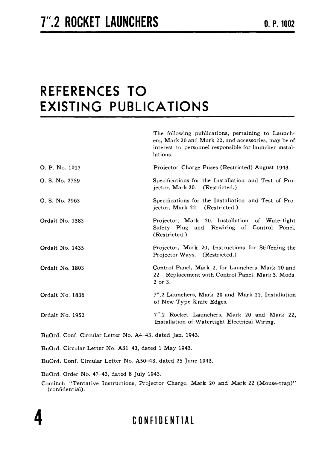
The following publications, pertaining to Launch- ers, Mark 20 and Mark 22, and accessories, may be of interest to personnel responsible for launcher instal- lations.
О. P. No. 1017 Projector Charge Fuzes (Restricted) August 1943.
O. S. No. 2759 Specifications for the Installation and Test of Pro- jector, Mark 20, (Restricted.)
0. S. No. 2963 Specifications for the Installation and Test of Pro- jector, Mark 22. (Restricted..)
Ordalt No. 1383 Projector, Mark 20, Installation of Watertight Safety Plug and Rewiring of Control Panel. (Restricted.)
Ordalt No. 1435 Projector, Mark 20, Instructions for Stiffening the Projector Ways. (Restricted.)
Ordalt No. 1803 Control Panel, Mark 2, for Launchers, Mark 20 and 22—Replacement with Control Panel, Mark 3, Mods- 2 or 3.
Ordalt No. 1836 7" .2 Launchers, Mark 20 and Mark 22, Installation of New Type Knife Edges.
Ordalt No. 1952 7".2 Rocket Launchers, Mark 20 and Mark 22, Installation of Watertight Electrical Wiring.
BuOrd. Conf. Circular Letter No. A4-43, dated Jan. 1943.
BuOrd. Circular Letter No. A31-43, dated 1 May 1943.
BuOrd. Conf. Circular Letter No. A50-43, dated 25 June 1943.
BuOrd. Order No. 47-43, dated 8 July 1943.
Cominch “Tentative Instructions, Projector Charge, Mark 20 and Mark 22 (Mouse-trap)”
(confidential).
4
CONFIDENTIAL
CONTENTS
О. P. 1002
Page
REFERENCES TO EXISTING PUBLICATIONS........................ 4
Chapter 1
7".2 ROCKET LAUNCHER, MARK 20.................................... 9
INTRODUCTION................................................ 9
DESCRIPTION................................................ 13
7".2 ROCKET LAUNCHER................................... 13
INSTALLATION........................................... 15
ELECTRICAL CONTROLS.................................... 17
FIRING PANELS.......................................... 21
Chapter 2
7".2 ROCKET AMMUNITION AND FUZES....................... 25
AMMUNITION............................................. 25
7"2 ROCKET............................................. 25
BODY............................................... 25
MOTOR.............................................. 27
PROPELLANT COMPONENTS.............................. 27
FUZE SEAT LINERS................................... 29
FUZES.................................................. 31
U.S. N. NOSE FUZE, MARK 131 (AND MODS.)................ 33
GENERAL............................................ 33
OPERATION.......................................... 33
SAFETY FEATURES.................................... 34
HANDLING........................................... 35
SPECIAL PRECAUTIONS................................ 35
U. S. N. NOSE FUZE, MARK 135 (AND MODS.)............... 37
GENERAL............................................ 37
OPERATION.......................................... 37
SAFETY FEATURES.................................. •• 38
CONFIDENTIAL
5
Г.2 ROCKET LAUNCHERS
О. P. 1002
Page
U. S. N. NOSE FUZE, MARK 140........................... 39
GENERAL............................................ 39
THE MECHANISM...................................... 41
EXPLOSIVE COMPONENTS............................... 41
OPERATION.......................................... 41
SAFETY FEATURES.................................... 42
ARMED FUZES........................................ 42
INSTALLING IN ROCKET............................... 43
POINTS TO CHECK.................................... 43
7"2 ROCKET ASSEMBLY SHEET.......................... 44
SERVICING ......................................... 46
PACKING AND MARKING................................ 46
Chapter 3
OPERATION AND MAINTENANCE 7".2 ROCKET LAUNCHER, MARK 20. 47
OPERATION.............................................. 47
STOWAGE AND ASSEMBLY............................... 47
LOADING AND FIRING................................. 48
SAFETY PRECAUTIONS................................. 49
MAINTENANCE........................................ 52
TACTICAL OPERATION................................. 52
Chapter 4
PERFORMANCE DATA OF 7",2 ROCKET LAUNCHER, MARK 20.. 53
PERFORMANCE............................................ 53
Chapter 5
COGNIZANCE
COGNIZANCE.................................................. 61
Chapter 6
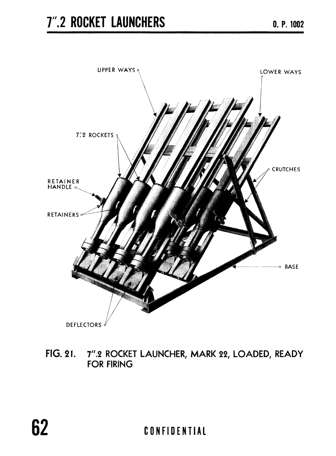
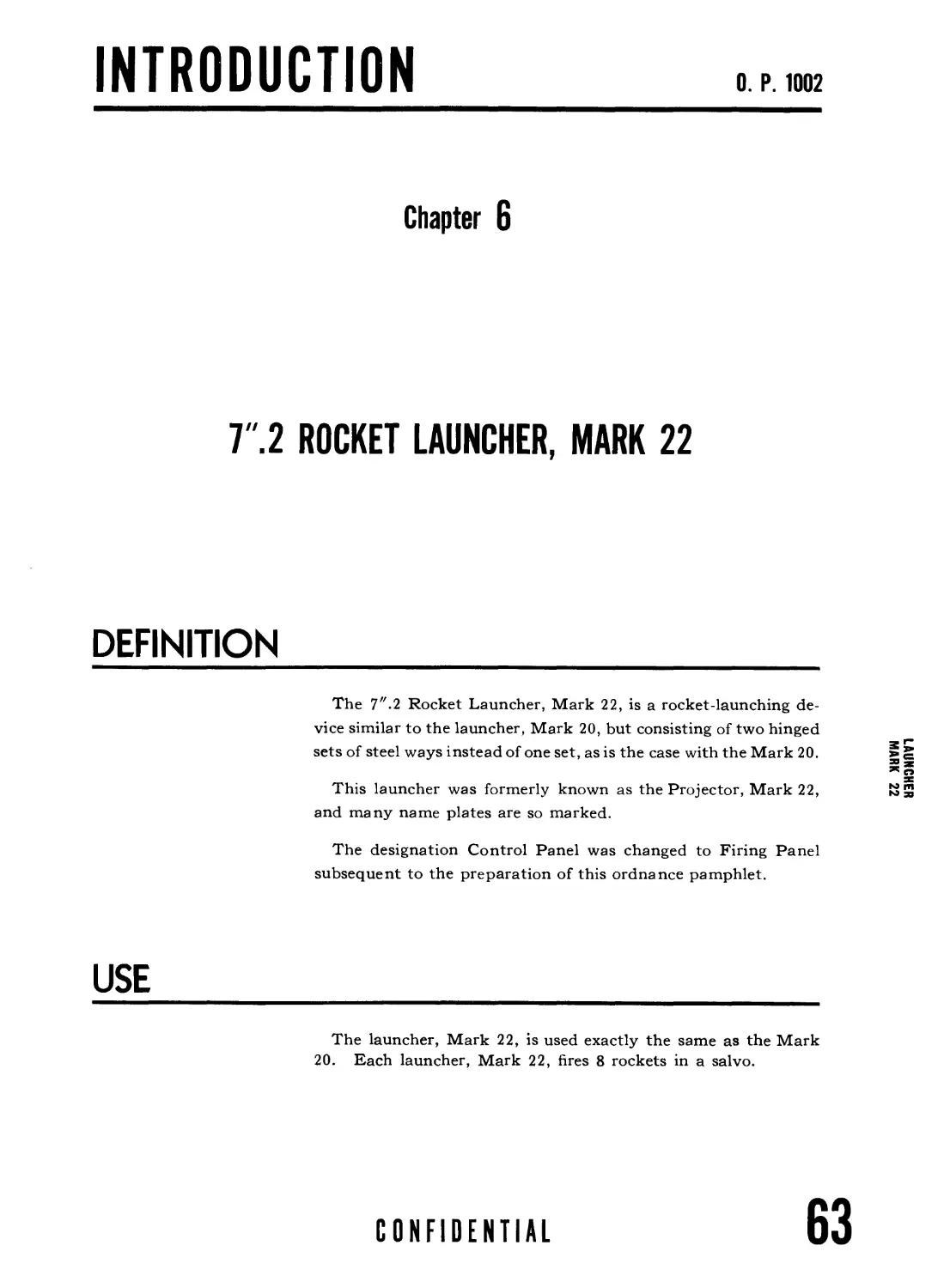
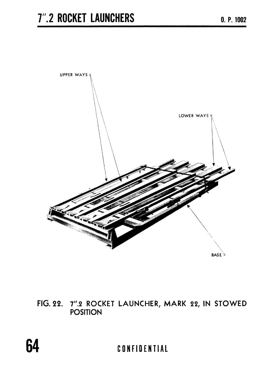
7".2 ROCKET LAUNCHER, MARK 22............................... 63
INTRODUCTION........................................... 63
DEFINITION......................................... 63
USE................................................ 63
DESCRIPTION............................................ 65
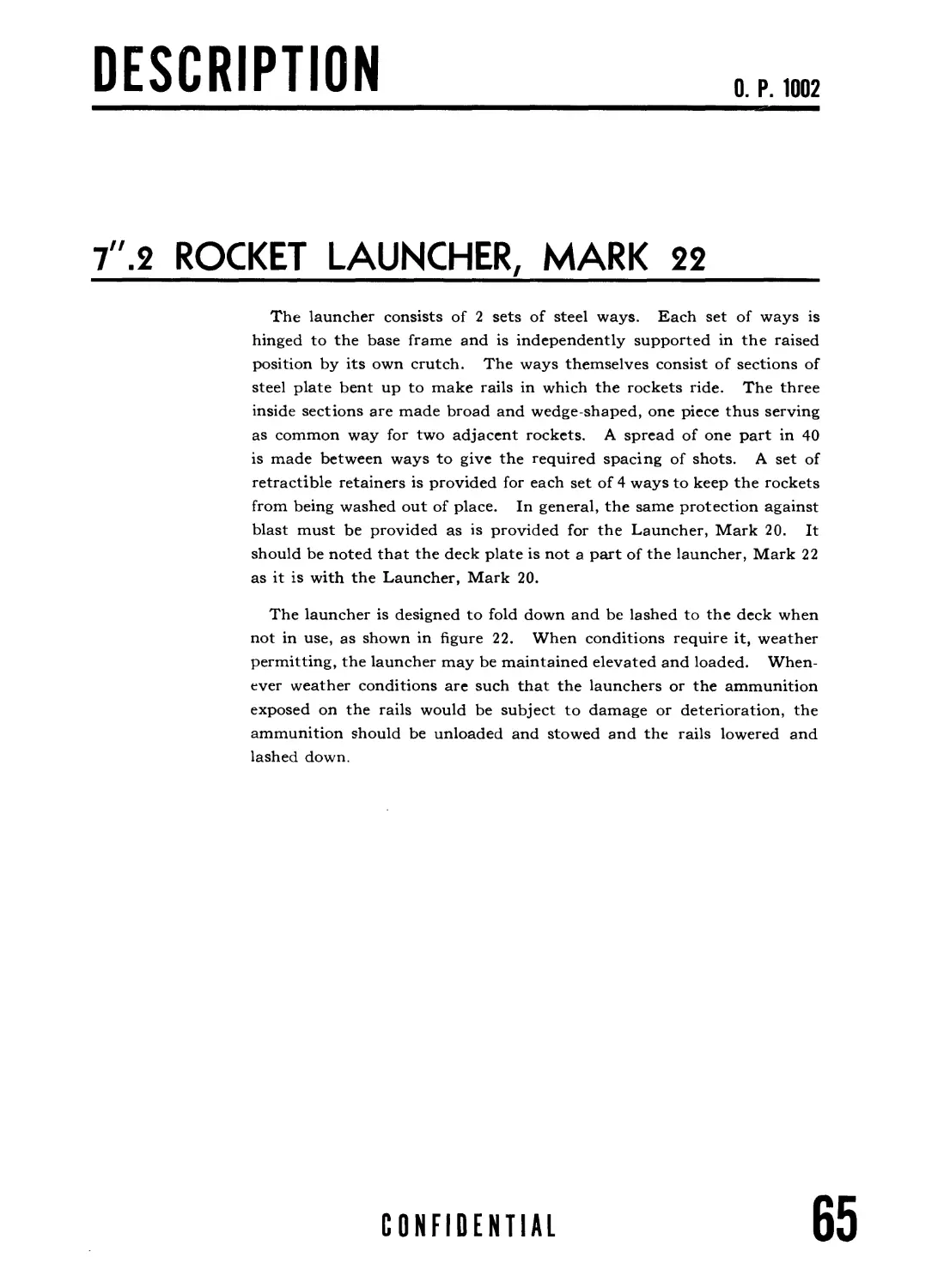
7ZZ.2 ROCKET LAUNCHER.............................. 65
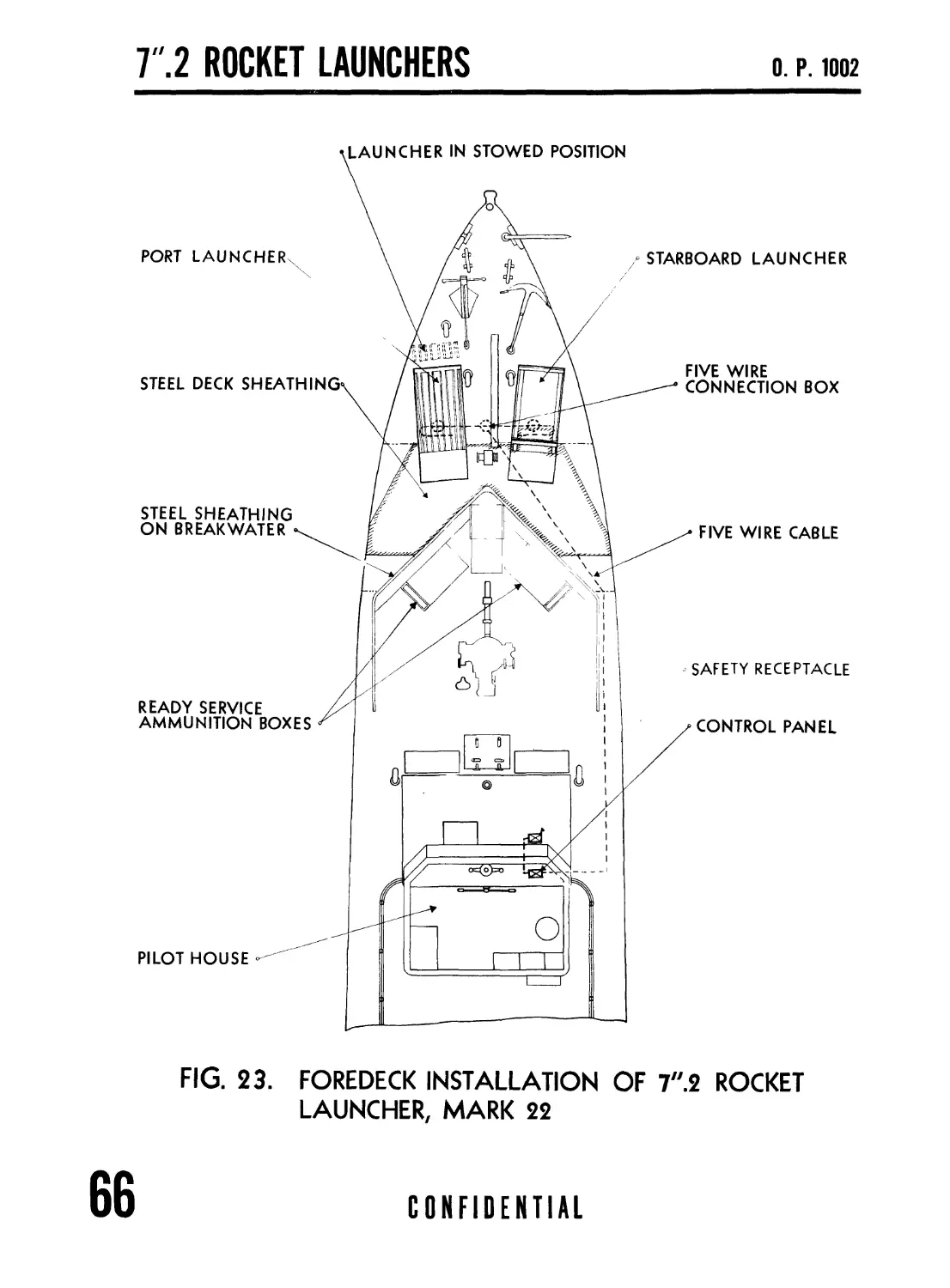
INSTALLATION....................................... 67
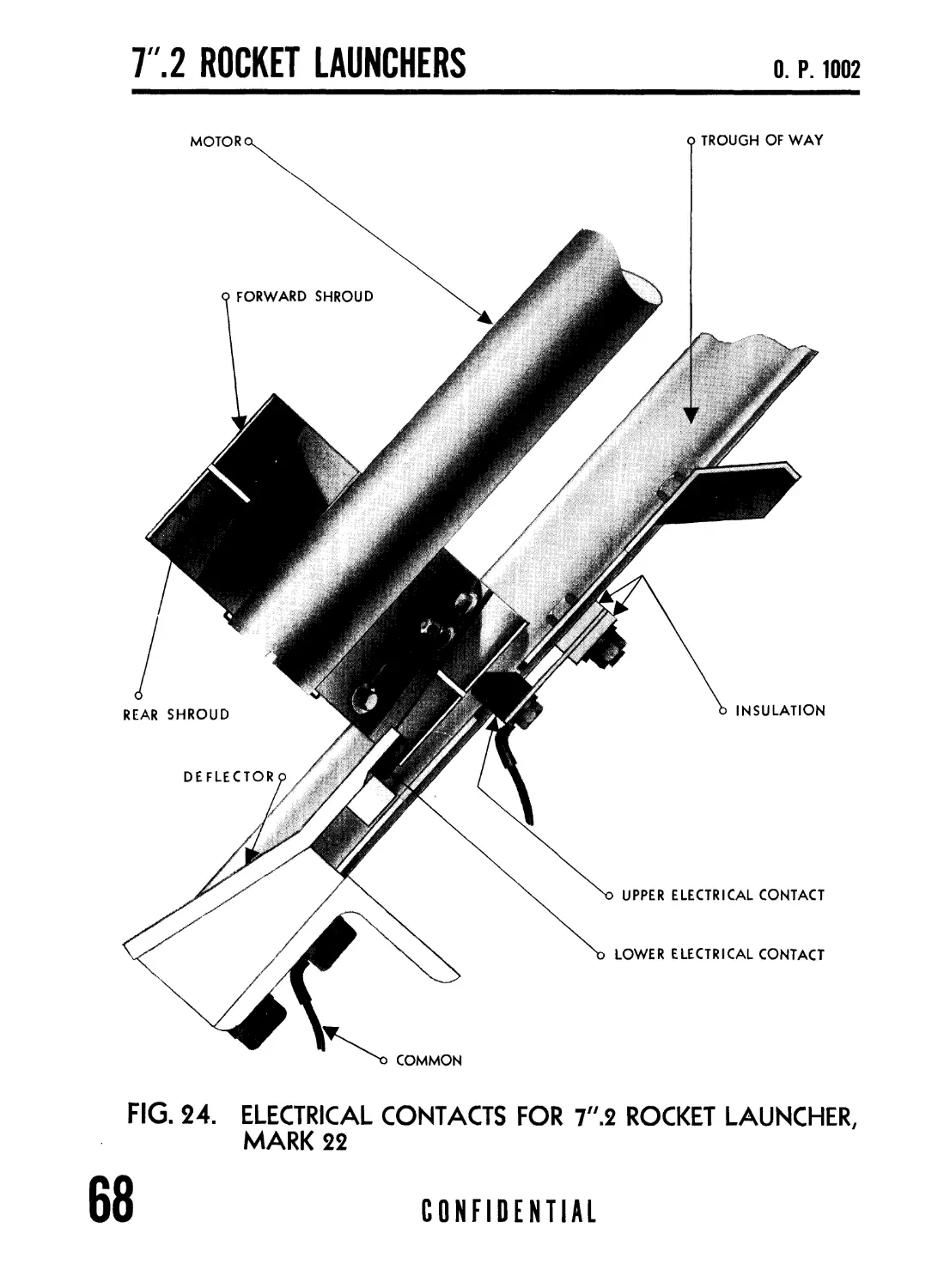
ELECTRICAL CONTROLS................................ 69
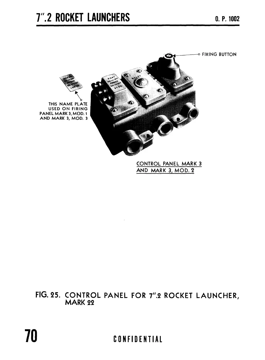
CONTROL PANELS..................................... 71
6
CONFIDENTIAL
CONTENTS
О. P. 1002
Page
Chapter 7
OPERATION AND MAINTENANCE 7".2 ROCKET LAUNCHER, MARK 22... 75
OPERATION............................................. 75
LOADING AND FIRING................................ 75
SAFETY PRECAUTIONS................................ 76
MAINTENANCE....................................... 77
ROCKET PERFORMANCE............................... 77
Chapter 8
COGNIZANCE
COGNIZANCE................................................. 79
Chapter 9
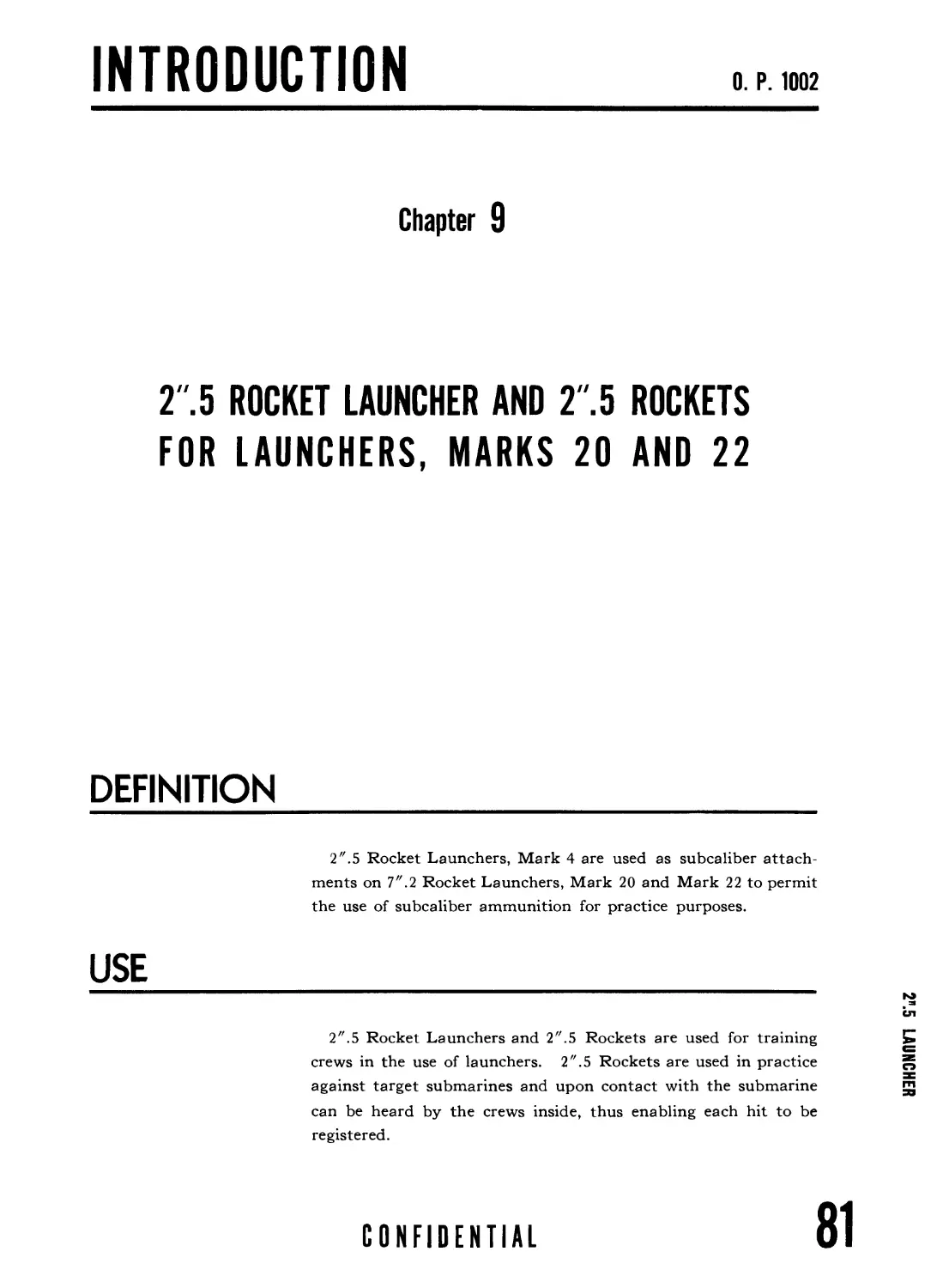
2".5 ROCKET LAUNCHER AND 2",5 ROCKETS FOR LAUNCHERS,
MARKS 20 AND 22............................................. 81
INTRODUCTION........................................... 81
DEFINITION......................................... 81
USE................................................ 81
AMMUNITION ............................................ 83
THE 2".5 ROCKET........................................ 83
GENERAL............................................ 83
INSTALLATION....................................... 83
BODY............................................... 83
MOTOR.............................................. 83
PROPELLANT COMPONENTS.............................. 83
OPERATION.............................................. 84
LOADING AND FIRING................................. 84
SAFETY PRECAUTIONS................................. 85
COGNIZANCE......................................... 85
DISTRIBUTION........................................... 87
CONFIDENTIAL
7
7 ".2 ROCKET LAUNCHERS
О. P. 1002
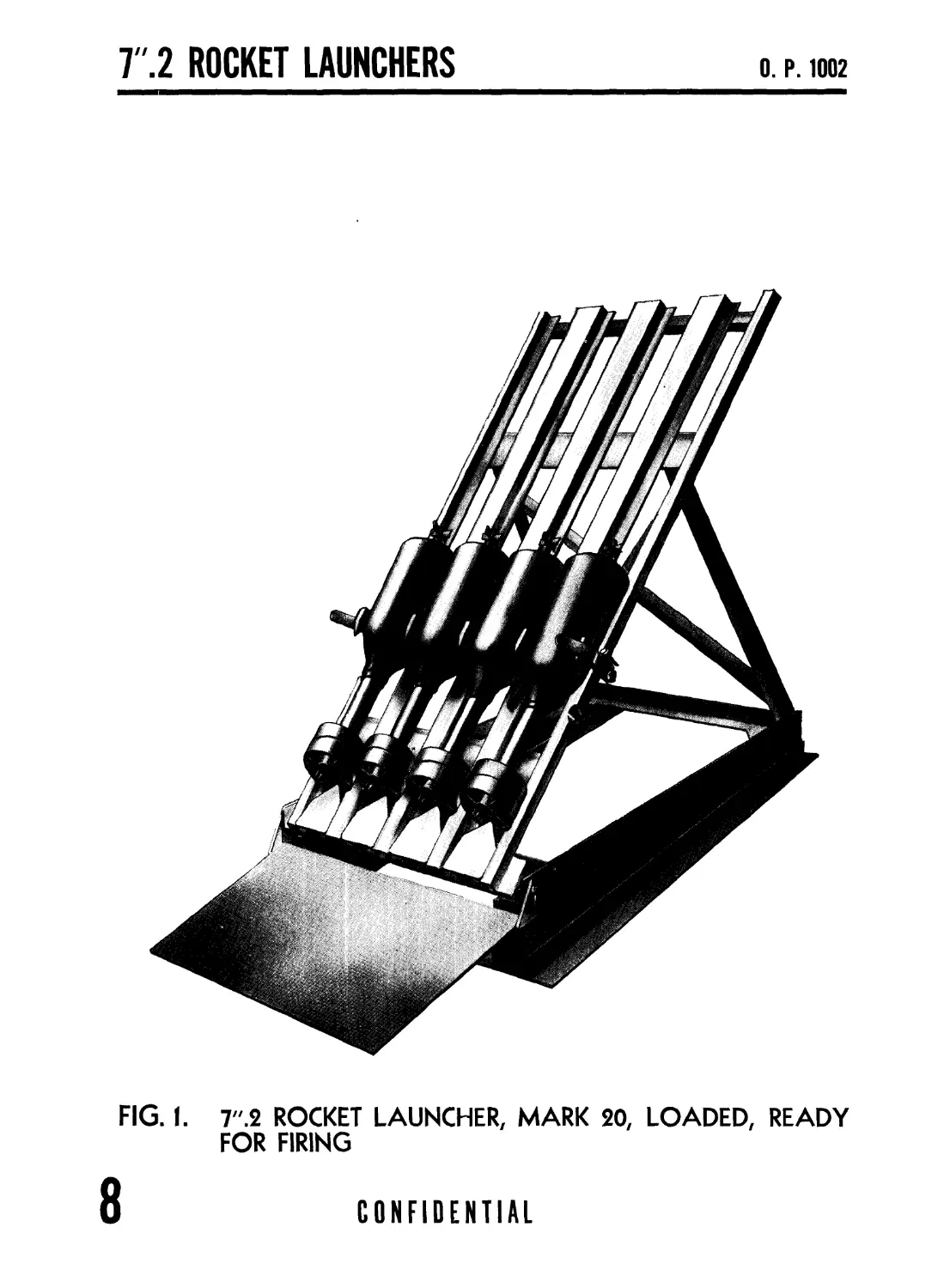
FIG. 1. 7".2 ROCKET LAUNCHER, MARK 20, LOADED, READY
FOR FIRING
8
CONFIDENTIAL
INTRODUCTION
О. P. 1002
Chapter 1
T.2 ROCKET LAUNCHER, MARK 20
DEFINITION
The 7".2 Rocket Launcher, Mark 20 (formerly known as the
“Mousetrap”) is a set of steel ways for supporting and firing 7".2
Rockets. This launcher was also formerly known as the Pro-
jector Mark 20, and many name plates are so marked.
The designation Control Panel was changed to Firing Panel
subsequent to the preparation of this Ordnance Pamphlet.
CONFIDENTIAL
9
Т.2 ROCKET LAUNCHERS
О. P. 1002
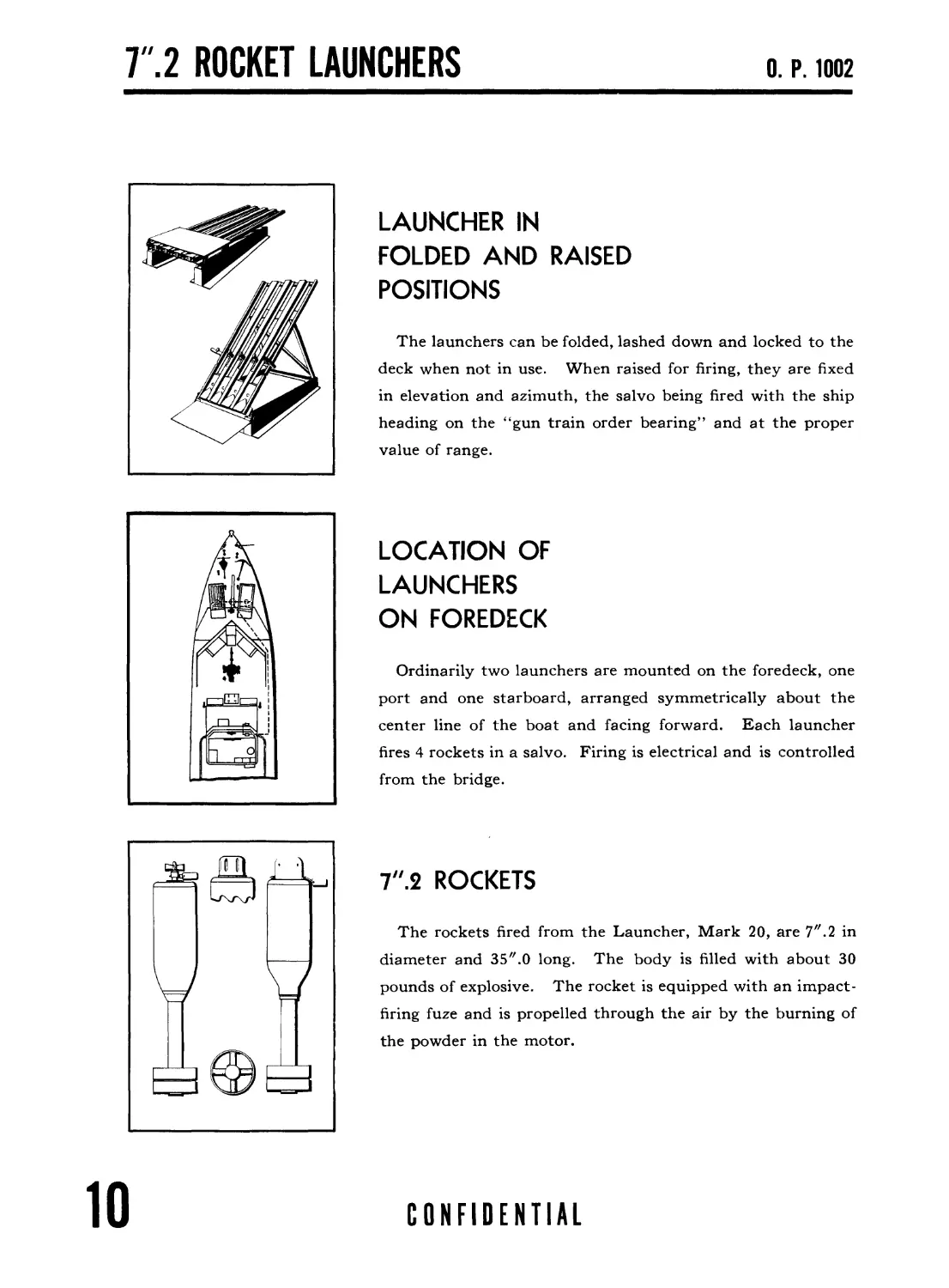
LAUNCHER IN
FOLDED AND RAISED
POSITIONS
The launchers can be folded, lashed down and locked to the
deck when not in use. When raised for firing, they are fixed
in elevation and azimuth, the salvo being fired with the ship
heading on the “gun train order bearing’’ and at the proper
value of range.
LOCATION OF
LAUNCHERS
ON FOREDECK
Ordinarily two launchers are mounted on the foredeck, one
port and one starboard, arranged symmetrically about the
center line of the boat and facing forward. Each launcher
fires 4 rockets in a salvo. Firing is electrical and is controlled
from the bridge.
7".2 ROCKETS
The rockets fired from the Launcher, Mark 20, are 7". 2 in
diameter and 35".0 long. The body is filled with about 30
pounds of explosive. The rocket is equipped with an impact-
firing fuze and is propelled through the air by the burning of
the powder in the motor.
10
CONFIDENTIAL
INTRODUCTION
LAUNCHER
MARK 20
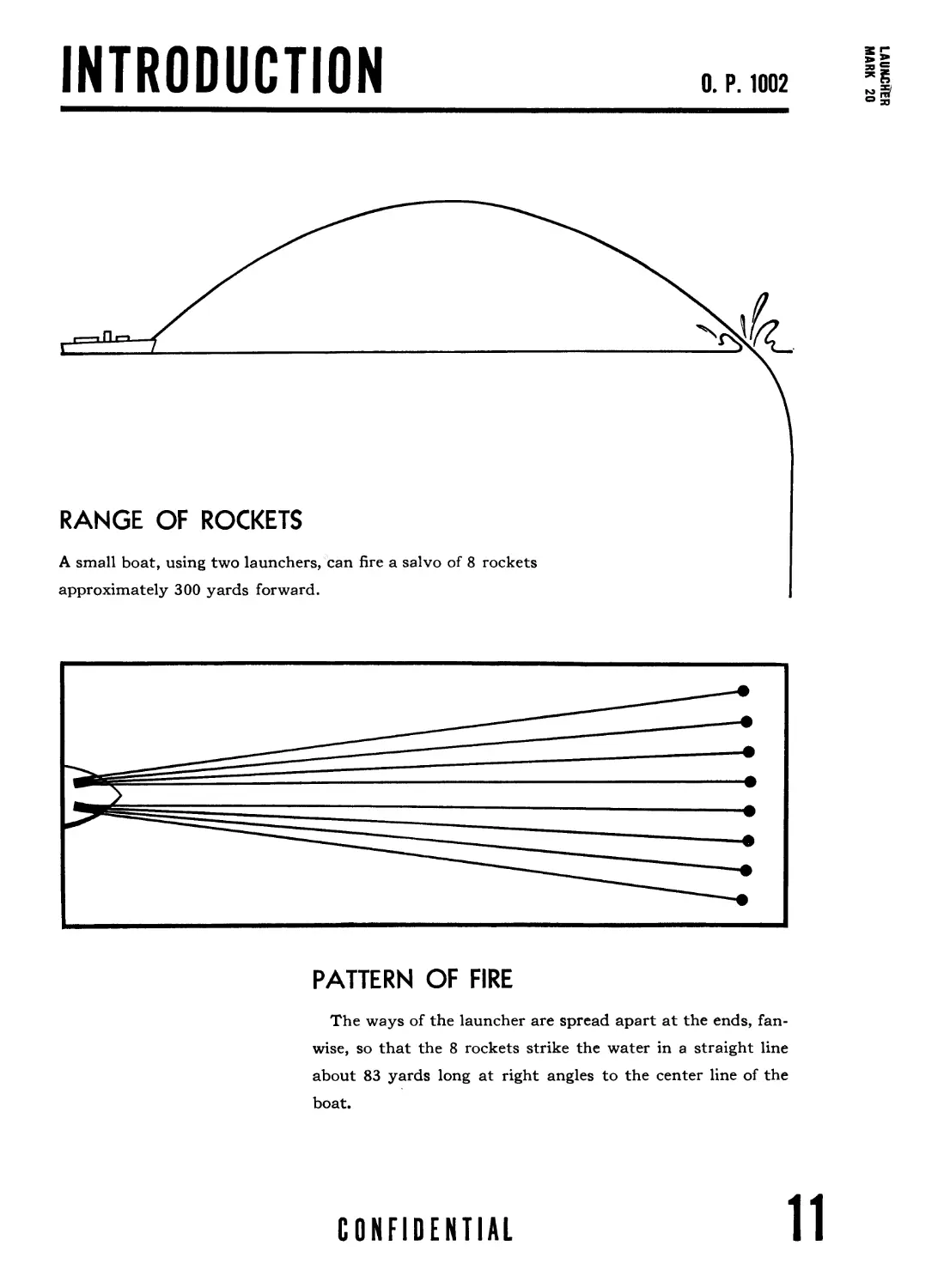
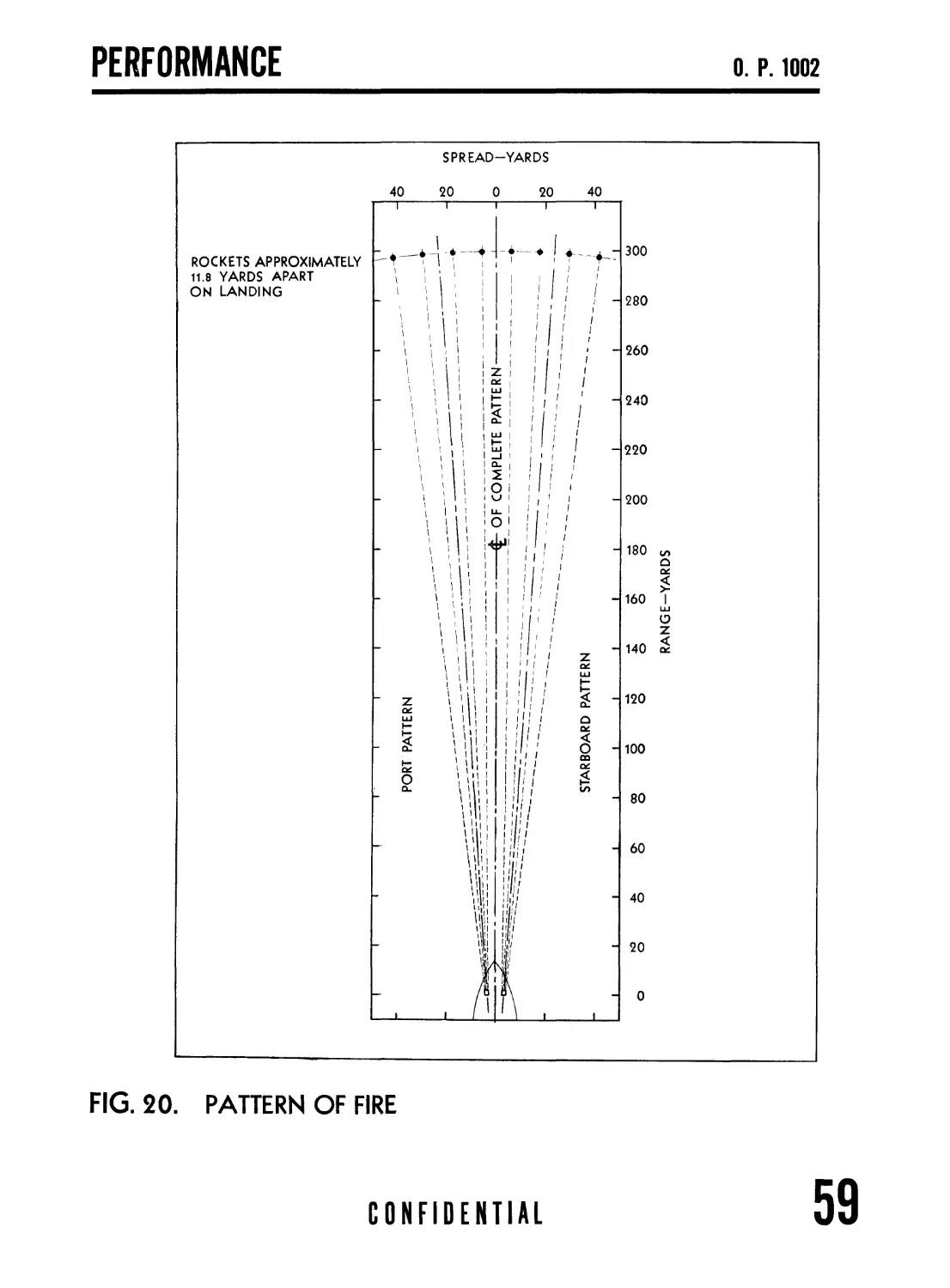
PATTERN OF FIRE
The ways of the launcher are spread apart at the ends, fan-
wise, so that the 8 rockets strike the water in a straight line
about 83 yards long at right angles to the center line of the
boat.
CONFIDENTIAL
11
Т.2 ROCKET LAUNCHERS
О. P. 1002
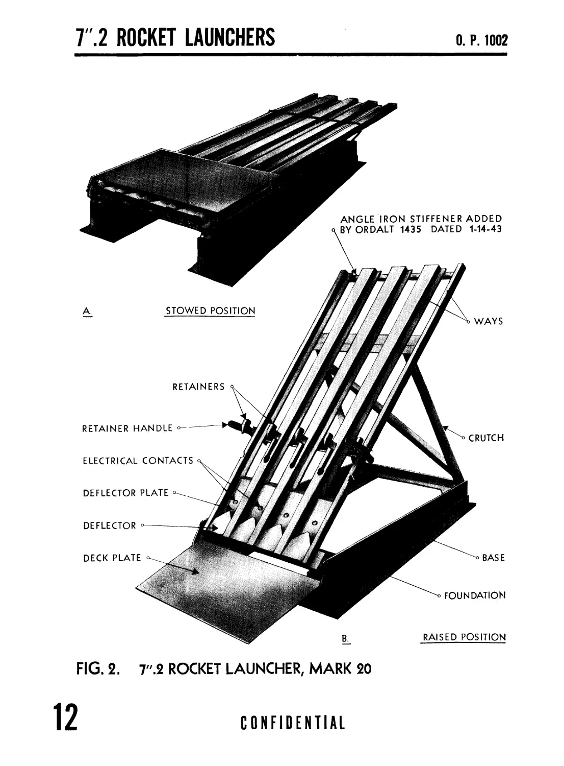
STOWED POSITION
RETAINERS
RETAINER HANDLE
ELECTRICAL CONTACTS
DEFLECTOR PLATE
DEFLECTOR -
DECK PLATE
ANGLE IRON STIFFENER ADDED
BY ORDALT 1435 DATED 1-14-43
WAYS
CRUTCH
BASE
FOUNDATION
RAISED POSITION
FIG. 2. 7".2 ROCKET LAUNCHER, MARK 20
12
CONFIDENTIAL
DESCRIPTION
0. Г. 1002
7".2 ROCKET LAUNCHER, MARK 20
The launcher consists of ways welded together to make a rigid
unit which is hinged to the base which in turn is fastened to the
deck structure. When erected, the ways are supported by a
crutch which also is hinged to the base and locks in place with
two levers. The ways themselves consist of sections of steel
plate bent up to make rails in which the rockets ride. The three
inside sections are made broad and wedge-shaped, one piece thus
serving as common rail for two adjacent rockets. A spread of
one part in 40 is made between ways to give the required spacing
of shots. A set of retractable retainers is provided to keep the
rockets from being washed out of place in a heavy sea. These
retainers are raised manually and pinned in place after the ways
are loaded. They do not interfere with the firing. In firing, an
intense blast of hot gases is ejected from the nozzles of the rocket
motors for several feet. Unless the deck and nearby structures
are protected, they are likely to be scorched considerably. To
divert the direct blast at the base of the projector, heavy steel
deflectors are provided and a %6-inch steel plate 24".0 long laid
on the deck immediately behind. For places not directly struck
by the blast, a light steel sheet is sufficient.
The launcher is designed to fold down and be lashed to the deck
when not in use, as shown in figure 2. When conditions require
it, weather permitting, the launcher may be maintained elevated
and loaded. Whenever weather conditions are such that the
launchers or the ammunition exposed on the rails would be sub-
ject to damage or deterioration, the ammunition should be
unloaded and stowed and the rails lowered and lashed down.
CONFIDENTIAL
13
7".2 ROCKET LAUNCHERS
О. P. 1002
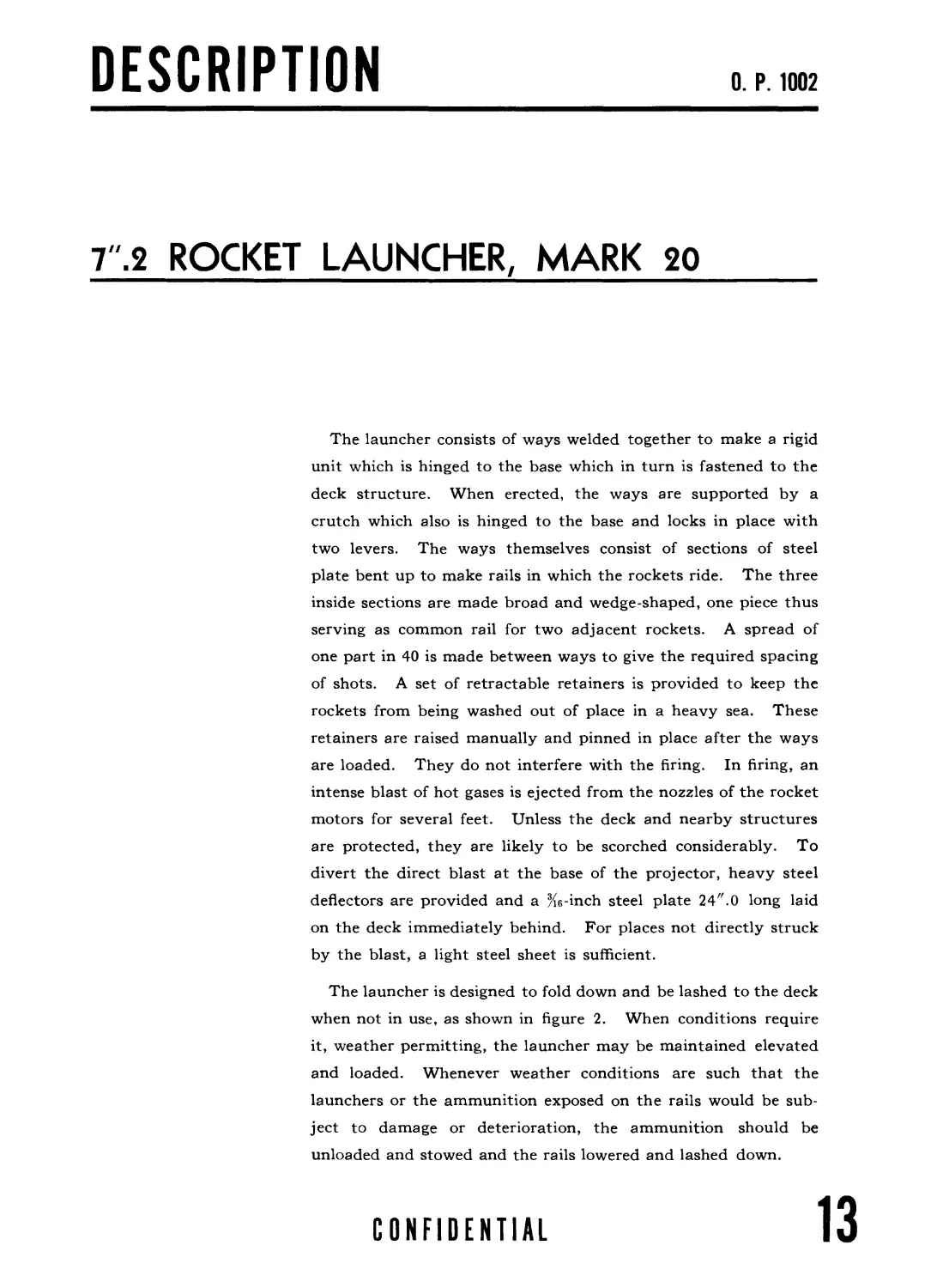
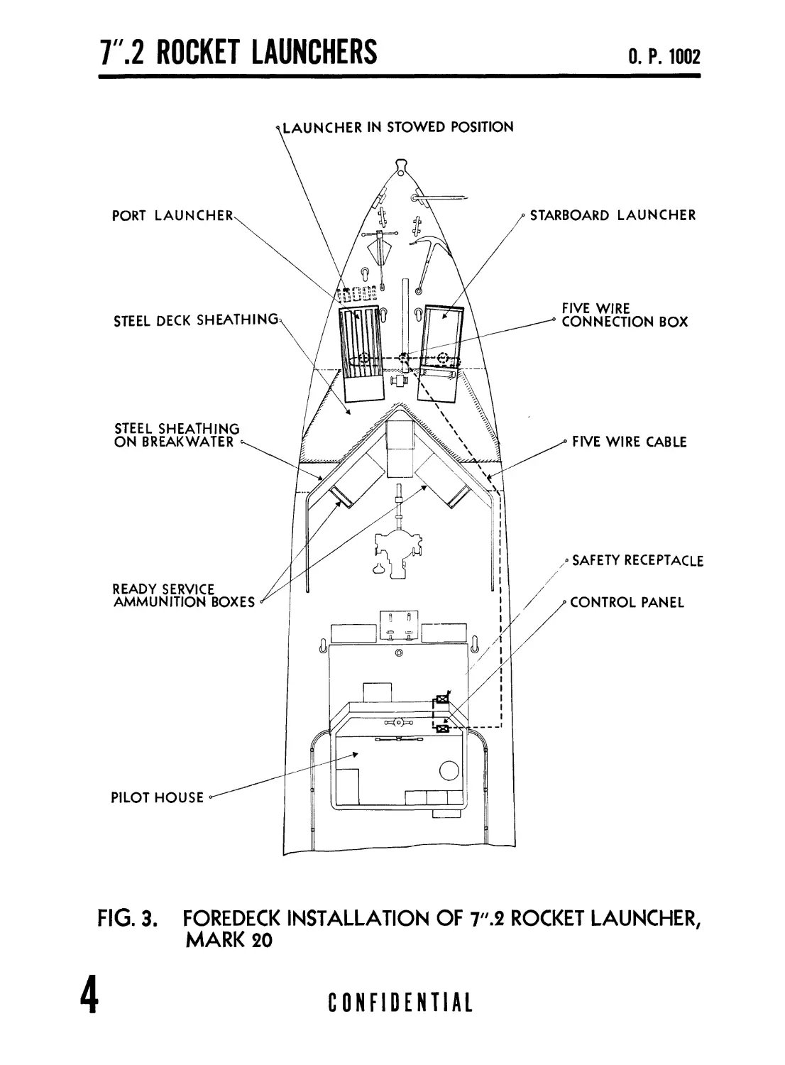
STEEL DECK SHEATHING
READY SERVICE
AMMUNITION BOXES
LAUNCHER IN STOWED POSITION
PORT LAUNCHER
PILOT HOUSE
STEEL SHEATHING
ON BREAKWATER
FIVE WIRE CABLE
SAFETY RECEPTACLE
CONTROL PANEL
FIVE WIRE
CONNECTION BOX
STARBOARD LAUNCHER
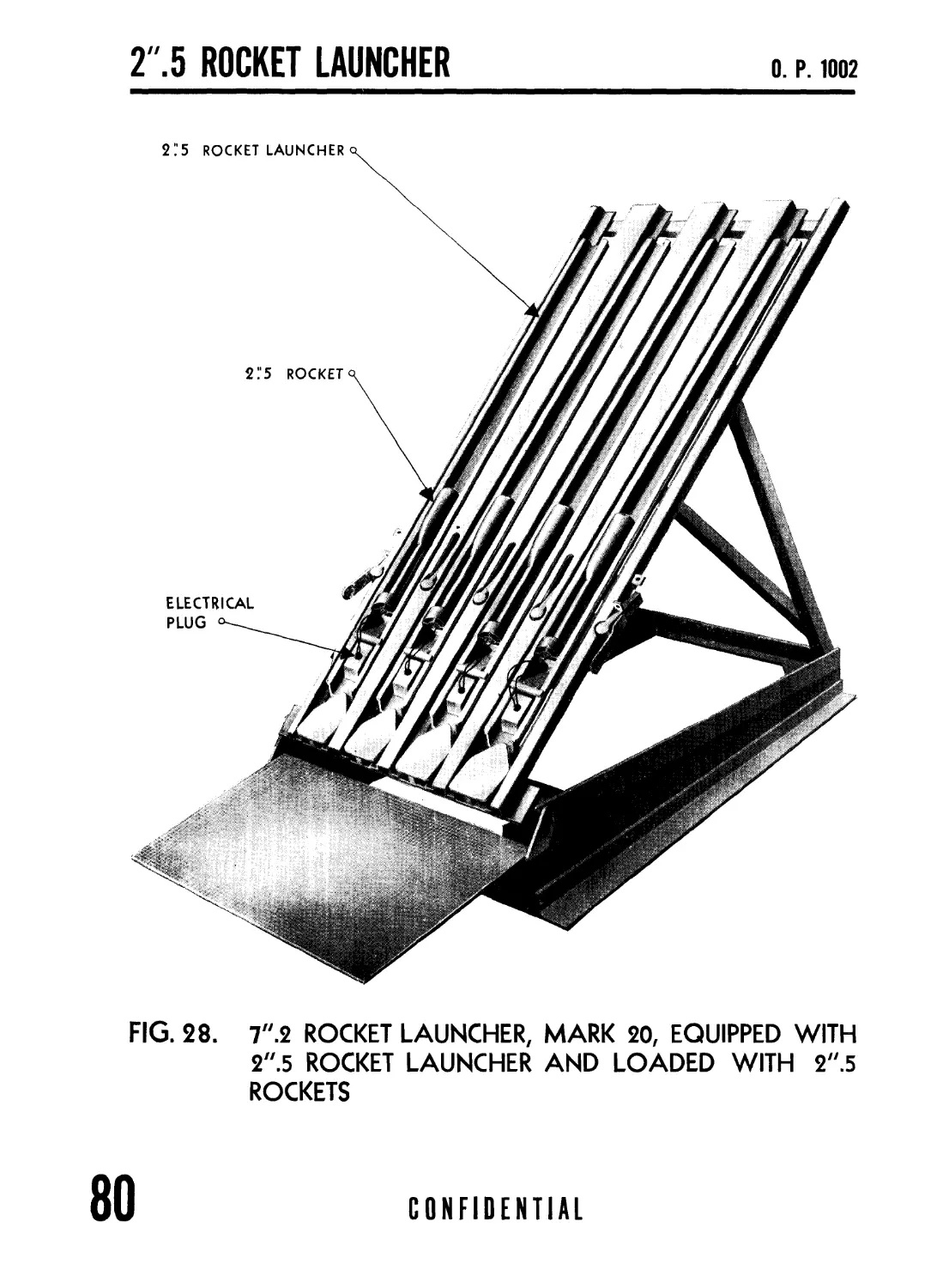
FIG. 3. FOREDECK INSTALLATION OF 7".2 ROCKET LAUNCHER,
MARK 20
4
CONFIDENTIAL
DESCRIPTION
0. F. 1002
INSTALLATION
The launchers are mounted on the foredeck (see fig. 3) requir-
ing two clear spaces about 38".0 by 84".0. All wooden struc-
tures directly aft are sheathed with Xe-inch steel sheet as pro-
tection against blast. Extending from the launcher, in the
direct line of the blast, a %6-inch steel floor plate about 2 feet
long is provided. The flame is of sufficient intensity to remove
paint from surfaces directly in line for the first 2 or 3 feet, so
frequent repainting of the sheathing may be necessary.
The launchers are mounted on wood or metal foundations so
that they are level athwartships and have a 3°-5° slope fore and
aft with the high point forward. The two launchers are placed,
in the folded position, on the foredeck symmetrically about the
centerline of the ship. The extreme forward point of the in-
board edge of the base of each launcher deviates 4 to 5 inches
further from the centerline than the aft end of the base. This
deviation is inversely proportional to the distance between
launchers. This placement of the launchers gives an approx
imately equal spacing to all 8 rockets.
Ready-service boxes are provided on the foredeck, convenient
to the launchers, for ready ammunition. Each box is water-
proof and holds 8 rounds in easily accessible racks. Additional
ammunition is stowed below decks in magazine stowage.
CONFIDENTIAL
15
Г.2 ROCKET LAUNCHERS
О. P. 1002
FIG. 4. ELECTRICAL CONTACTS FOR 7".2 ROCKET LAUNCHER,
MARK 20
16
CONFIDENTIAL
DESCRIPTION
0. P. WOP
ELECTRICAL
CONTROLS
ELECTRICAL CONTROLS
Electrical contact for firing is made to the two shrouds of the
rocket motor by means of knife edges (see fig. 4). The lower
contact mounted in the deflector plate grips the inside of the
grounded rear motor shroud, which is electrically connected to
one side of the igniter, and serves as a stop. The upper insulated
contact is mounted on a phosphor bronze spring and bears on
the outside of the insulated forward shroud. Both contacts are
made of hardened stainless steel.
CONFIDENTIAL
17
Т.2 ROCKET LAUNCHERS
О. P. 1002
FIG. 5. CIRCUIT SCHEMATIC FOR 7."2 ROCKET LAUNCHER,
MARK 20
(USING CONTROL PANEL, MARK 2, MOD. 2)
A cable with 5 active conductors runs from the control panel to a 5-wire connection box.
From this box, a cable runs to a branch box Type E at each launcher, and thence to the launcher.
In certain installations, the cable from the control panel passes through the deck through a
watertight bushing to a 5-wire connection box. For schematic diagrams of the circuits, see
figures 5 and 6.
18
CONFIDENTIAL
DESCRIPTION
О. P. 1002
FIG. 6. CIRCUIT SCHEMATIC FOR 7".2 ROCKET LAUNCHER,
MARK 20
(USING CONTROL PANEL, MARK 3, MOD. 2)
The control panel is located on the bridge. From the control panel, a 4-conductor cable runs
to a safety plug receptacle. All connections are broken in this receptacle unless the safety
plug is in place. The safety receptacle is usually mounted on the side of the bridge structure
in a position protected from blast and at a safe distance from the launchers.
CONFIDENTIAL
19
Т.2 ROCKET LAUNCHERS
О. P. 1002
THIS NAME PLATE
USED ON CONTROL
PANEL MARK3,MOD.1
AND MARK 3,MOD. 3
FIRING BUTTON
CONTROL PANEL MARK 3
AND MARK 3, MOD. 2
PLUG RECEPTACLE *
TERMINAL TUBE
TO SAFETY PLUG
(ADDED BY ORDALT
1383 DATED 12-18-42)
CONTROL PANEL
MARK 2, MOD. 2
FIG. 7.
CONTROL PANELS FOR 7".2 ROCKET LAUNCHERS,
MARK 20 AND MARK 22
20
CONFIDENTIAL
DESCRIPTION
О. P. 1002
CONTROL PANELS
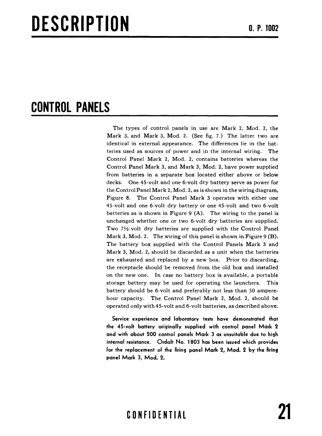
The types of control panels in use are Mark 2, Mod. 2, the
Mark 3, and Mark 3, Mod. 2. (See fig. 7.) The latter two are
identical in external appearance. The differences lie in the bat-
teries used as sources of power and in the internal wiring. The
Control Panel Mark 2, Mod. 2, contains batteries whereas the
Control Panel Mark 3, and Mark 3, Mod. 2, have power supplied
from batteries in a separate box located either above or below
decks. One 45-volt and one б-volt dry battery serve as power for
the Control Panel Mark 2, Mod. 2, as is shown in the wiring diagram,
Figure 8. The Control Panel Mark 3 operates with either one
45-volt and one б-volt dry battery or one 45-volt and two 6-volt
batteries as is shown in Figure 9 (A). The wiring to the panel is
unchanged whether one or two б-volt dry batteries are supplied.
Two 7H-volt dry batteries are supplied with the Control Panel
Mark 3, Mod. 2. The wiring of this panel is shown in Figure 9 (B).
The battery box supplied with the Control Panels Mark 3 and
Mark 3, Mod. 2, should be discarded as a unit when the batteries
are exhausted and replaced by a new box. Prior to discarding,
the receptacle should be removed from the old box and installed
on the new one. In case no battery box is available, a portable
storage battery may be used for operating the launchers. This
battery should be 6-volt and preferably not less than 50 ampere-
hour capacity. The Control Panel Mark 2, Mod. 2, should be
operated only with 45-volt and 6-volt batteries, as described above.
Service experience and laboratory tests have demonstrated that
the 45-volt battery originally supplied with control panel Mark 2
and with about 200 control panels Mark 3 as unsuitable due to high
internal resistance. Ordalt No. 1803 has been issued which provides
lor the replacement of the Firing panel Mark 2, Mod. 2 by the firing
panel Mark 3, Mod. 2.
CONFIDENTIAL
21
Т.2 ROCKET LAUNCHERS
О. P. 1002
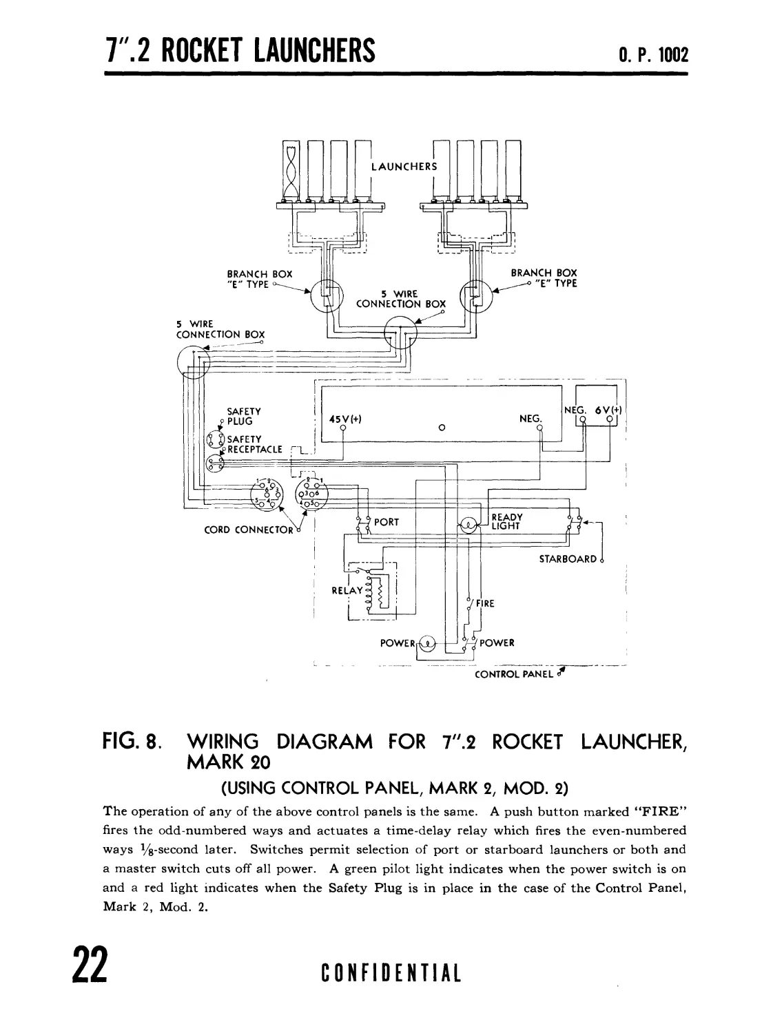
FIG. 8. WIRING DIAGRAM FOR 7".2 ROCKET LAUNCHER,
MARK 20
(USING CONTROL PANEL, MARK 2, MOD. 2)
The operation of any of the above control panels is the same. A push button marked “FIRE”
fires the odd-numbered ways and actuates a time-delay relay which fires the even-numbered
ways Ve-second later. Switches permit selection of port or starboard launchers or both and
a master switch cuts off all power. A green pilot light indicates when the power switch is on
and a red light indicates when the Safety Plug is in place in the case of the Control Panel,
Mark 2, Mod. 2.
22
CONFIDENTIAL
DESCRIPTION
О. P. 1002
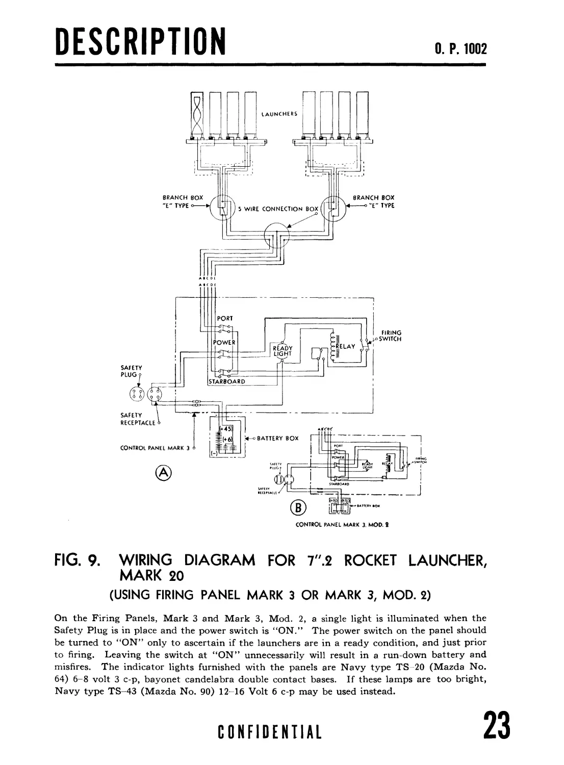
FIG. 9. WIRING DIAGRAM FOR 7".2 ROCKET LAUNCHER,
MARK 20
(USING FIRING PANEL MARK 3 OR MARK 3, MOD. 2)
On the Firing Panels, Mark 3 and Mark 3, Mod. 2, a single light is illuminated when the
Safety Plug is in place and the power switch is “ON.” The power switch on the panel should
be turned to “ON” only to ascertain if the launchers are in a ready condition, and just prior
to firing. Leaving the switch at “ON” unnecessarily will result in a run-down battery and
misfires. The indicator lights furnished with the panels are Navy type TS 20 (Mazda No.
64) 6-8 volt 3 c-p, bayonet candelabra double contact bases. If these lamps are too bright,
Navy type TS-43 (Mazda No. 90) 12-16 Volt 6 c-p may be used instead.
CONFIDENTIAL
23
Т.2 ROCKET LAUNCHERS
О. P. 1002
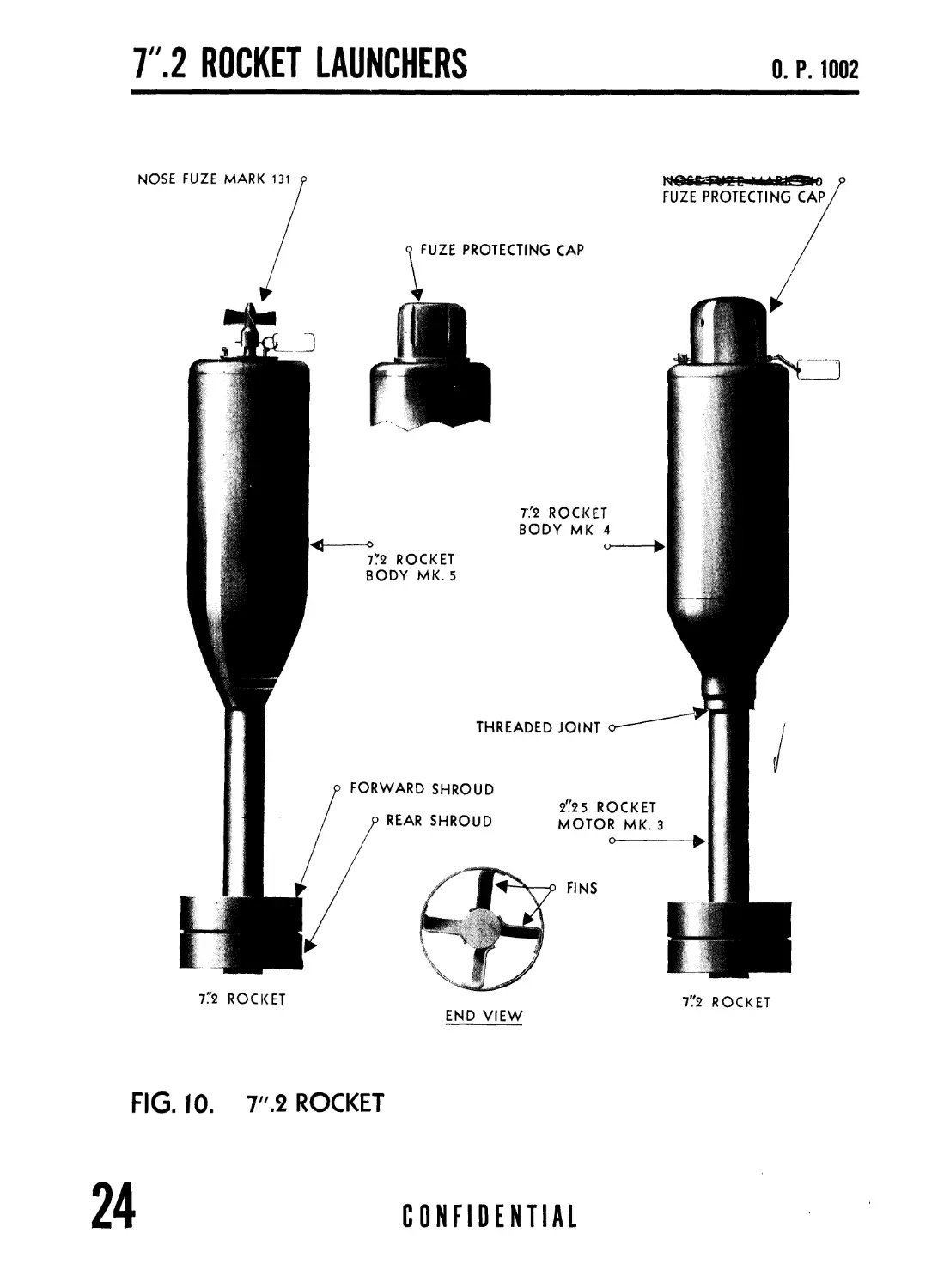
FIG. 10. 7".2 ROCKET
24
CONFIDENTIAL
AMMUNITION
О. P. 1002
Chapter 2
7".2 ROCKET AMMUNITION AND FUZES
7".2 ROCKETS
7' .2 ROCKET AMMUNITION
Two general views of the 7".2 Rocket ammunition for use with
Launchers, Mark 20 and 22, are shown in figure 10. The units
consist of the body, the motor, and the fuze. The body is 7.2
inches in maximum diameter and the assembled projectile weighs
about 63 pounds. The entire unit is streamlined and provided
with fins to give stable flight and a high sinking rate in water.
The body of the projectile is filled with approximately 30
pounds of TNT or 34 pounds of TPX. An auxiliary booster
consisting of granular TNT is employed to detonate this charge.
BODY
The body for 7".2 Rocket ammunition is a welded steel cylin-
drical case, with a relatively flat nose section and a conical tail
fairing. It is provided with an opening in the nose section to
receive the fuze seat liner and the fuze. Originally the body was
designed for nose filling and the fuze seat liner was screwed into
the nose. Later designs provide for filling through the rear and
the fuze seat liner in these bodies is integral with the body.
The body, Mark 4, and motor, Mark 3, are assembled by screw-
ing the motor into the threaded cone bushing of the body. The
newer body (Mark 5) with integral fuze seat liner uses a connector
closure into which an adapter is screwed which, in turn, accom-
modates the motor. The design of this body not only permits
of pouring of the high explosive through the rear opening but also
permits the use of a larger motor when the adapter is omitted,
thus allowing other applications of this body.
CONFIDENTIAL
25
7".2 ROCKET LAUNCHERS
О. P. 1002
FRONT CLOSURE DISC
IGNITER
INSULATED WIRES
SECTION A-A
PERSPECTIVE OF POWDER GRAIN
INSULATION
SHROUDS
MACHINE
SCREW о
GRID
o INSULATED WIRE
-o INSULATED WASHER
DESICCANT BAG
NOZZLE CLOSURE
DISC
POWDER
GRAIN o
FIG. 11
DIAGRAMMATIC SKETCH OF ROCKET MOTOR
(SHOWING DETAILS OF TYPICAL PROPELLANT ASSEMBLAGE)
26
CONFIDENTIAL
AMMUNITION
О. P. 1002
MOTOR
The motor consists of a steel tube having an outside diameter of
2.25 inches, 4 radial fins and a cylindrical shroud surrounding the
fins (see fig. 11). The forward end of the motor tube is externally
threaded for assembly with the body. The fins are inclined 10°
relative to the tube axis. This design is intended to impart
rotation to the rocket and to cancel “ruddering” effects which
would disturb the underwater trajectory.
PROPELLANT COMPONENTS
The propellant components are contained in the motor. A
typical assembly of the components is shown in figure 11. The
main component is a single grain of solventless extruded ballistite
powder. At the forward end of this powder grain is located an
igniter which consists of an electrical squib leading into a charge
of black powder. Two electrical wires are run from the motor
shrouds through a central perforation in the powder grain to the
igniter. When the electrical circuit is closed, the igniter burns,
igniting the propellant grain which burns uniformly on all sur-
faces at a pressure of 800 to 2,300 pounds per square inch, depend-
ing upon temperature. The gases evolved are forced out through
the nozzle at high velocity and, by their reaction on the motor,
propel the unit forward. The propulsion does not depend on
any interaction with the air or upon the shields struck by the
blast, so no recoil problem exists. It is this feature which makes
the use of such equipment possible on relatively light boats.
The burning continues for about 0.4 second at normal tempera-
ture, while the rocket travels about 33 feet. After this period,
no further propulsion occurs and the rocket is in free flight.
CONFIDENTIAL
27
)r'
^.yApNCHERS
0. P. 1002
U. S. N. NOSE FUZE, MARK 131
U.S.N» NOSE FUZE-MARK 131
SAFETY PIN MUST
к BE IN POSITION
M DURING TRANSIT
AND STORAGE.
U. S. NOSE FUZE, MARK 135
FIG. 13
30
CONFIDENTIAL
AMMUNITION
0. P. 1002
FUZE SEAT LINERS
(See fig. 12). A threaded opening is provided in the 7".2
Rocket body, Mark 4, into which the fuze seat liner is screwed.
The fuze seat liner is threaded externally to fit this threaded
opening in the body head and is threaded internally to fit the
fuze threads. A formed, light metal extension or liner perma-
nently fixed to the fuze seat liner head forms the cavity for the
fuze and auxiliary booster. The fuze seat liner flange is provided
with hooks for engaging the fuze cap when the Mark 131 fuze is
used. This fuze cap is intended to protect the propeller vanes of
the Mark 131 fuze and should remain in place until the rocket is
loaded on the launcher way.
The fuze seat liner is an integral part of the T".2 Rocket body,
Mark 5.
CONFIDENTIAL
29
AMMUNITION
О. P. 1002
FUZES
THE FUZES
One of the three fuzes is used with 7". 2 Rockets as follows:
1. U. S. N. Nose Fuze, Mark 131 and Mods. (Uses one
Mark 1 (3-inch) booster.)
2. U. S. N. Nose Fuze, Mark 135 and Mods. (Used only in
bodies provided with a special fuze seat liner. Uses one
Mark 1 booster.)
3. U. S. N. Nose Fuze, Mark 140 and Mods. (Uses two Mark 2
(2-inch) boosters.)
These fuzes are armed after entering the water and all fire
upon impact with the steel surface or the wood deck gratings of
a submarine or other submerged object.
The fuze is screwed into the fuze seat liner of the Mark 4 body
or directly into the Mark 5 body. Before the fuze is screwed into
the body, inspection should be made to ascertain that the auxiliary
booster is present in the fuze liner and that the cardboard shipping
cylinder is removed.
CONFIDENTIAL
31
Т.2 ROCKET LAUNCHERS
О. P. 1002
BOOSTER CASE
STOP PIN
FUZE BODY
BOOSTER PELLET
LEAD-IN-LOAD
DETONATOR
LEAD-IN-DISC
В i
SECTION B-B
COLLAR
HUB \ i
1
ARMING VANEi
UNARMED POSITION
SAFETY PIN
SET SCREW
STOP
PIN SLEEVE
SPRING
SAFETY
BE IN
DURING
AND
SLEEVE
FIRING
SLEEVE
3 BALLS
RETAINING RING
GASKET
SET-BACK
PIN MUST
POSITION
TRANSIT
STORAGE
SECTION A-A
FIRING PIN
SPRING
FIRING PIN
WEIGHT
SEALING COLLAR
SEALING
WASHER
FUZE-PLUG
ARMING SCREW
SPRING PLATE
VANE SHEAR WIRE
arming Vane hub
LOCKING PINS
FRONT VIEW
FIG. 14. U. S. N. NOSE FUZE, MARK 131
SHUTTER SPRING
-° SHUTTER
STOP PIN
DETONATOR
32 CONFIDENTIAL
FUZES
0. P. 1002
U.S.N. NOSE FUZE, MARK 131 (AND MODS.)
GENERAL
The Nose Fuze, Mark 131, in general a counterpart of the British Fuze No. 420, except that
the collar shear wire is omitted, is illustrated in Figure 14.
NOTE. The Nose Fuze, Mark 131, is identical in appearance to the Fuze, Mark 136, which
is used in the projectile charge, except that the nose of Nose Fuze, Mark 131, is painted red.
The Nose Fuze, Mark 136, has a collar shear wire and since the set back in rockets is not
sufficient to shear this wire, it should never be used in rockets.
Arming the fuze is accomplished after the fuze strikes the water and has sunk to between
10 and 15 feet below the surface. Seven complete revolutions of the arming vanes are required
for complete arming, although it will probably be sufficiently armed to fire on side impact
after only 4 complete revolutions of the vane.
Detonation of the fuze is accomplished by impact, either direct, oblique, or glancing, on an
immersed object after the rocket has sunk beyond the arming distance of between 10 and 15 feet.
Generally, the fuze will not operate on striking and sinking into soft sea bottoms.
OPERATION
The fuzes are issued with the tagged safety pin in place. This pin passes through the
arming screw, fuze plug, and set-back collar and should remain in place until after the fuzed
rockets have been positioned on the launcher ways, at which time it should be removed.
The fuze caps should remain in place on fuzed rockets at all times—until just before firing—
to avoid damage to fuzes by handling or by exposure to weather.
Prior to firing from the launcher, the arming vane is prevented from rotating by the
set-back collar which engages locking pins in the arming vane hub and the plug. These
pins fit in a slot in the set-back collar and positively lock the arming vane until set-back
force causes the set-back collar to move backward on the plug. The vane is further secured
against rotation by a vane shear wire which fixes the arming vane hub directly to the fuze plug.
When the rocket is fired from the launcher, the set-back collar moves rearward due to
its inertia and is retained in this rearward position by a small spring plate which drops behind
the fuze plug pin.
NOTE. When ope’ratingii/'dempej^tureshelo.W 50° F., the setd5$ck c.oliafr on Xhe.-Mark
131, and mods. &nly/ (expCpy'Mark'134~lzfuzes-4rom^6'ty‘ 6M',? /М, 8M, and <>M) may
be retracted byzhapd after /the pdckpf i^ in pla'ce gn’' thglaunch^rj ,ih ordpr to insure arming
after water Дгпра/t^dThj/ pydcautfon-' is nec^ssa/y, si#qezat Ig.wXempera'ttH'es the set-back is
less than/dat n/rrrial or high tjpn^perature^^.-’RetrXcHon of/’the coll^/JzFy hand under other
conditions is/irot desirable, b^tfause thiJs"remov,e$ one safety featqfe. The vane shear wire
CONFIDENTIAL
33
Т.2 ROCKET LAUNCHERS
О. P. 1002
remains, it is Vue> but this could' be severed by heavy impact of sea water coming over the
bow, and the ffize armed by subp'e^/ient spray. Under such sta'con^litions, the set-back collar
should not be rietracfed uijtil just before firing, in cold weathfer or vfith sticky/collars. If the
fuze is not fired, the cpllat should be replaced. ’ 1 \ \
After the set-back collar has moved rearward, the arming vans is restricted against rota-
tion, during air flight,.by ths Vane shear wire. Upon striking the water, the tbr^ue imposed on
the vane by the yvateT action shears the vane shear wirre, allowing the vane to rotate: &sthe charge
sinks. As the Vane. rotates, the arming screZv moVes forward, allowing th^ weight, together
with, the associated firing pin, firing pin locking balU, firing pin spring and firing pin sleeve, to
also move forward under the influence of the compressed sleeve spring.. Thjs action places
the weight in its armed, position, free to oscillate about its base, and allows the dbtonatdr shunter
to Spring into an arrned position in alignment with the firing pin. As the firing pin sleeve
moves forward, the 4 stops фе released, and moved inward by their springs. These, detertts
prevent the firing pin from b£ing forced against the detonator by rotation of the arming vane
and screw in the reVetse direction when unarming an/inadvertently armed, fuze by hand in ap
effort to render it^safe to handle.
With the fuze ip the arnled condition described above, any blow which wiU cause the weight
'’S' ' \ F • . \ I
to oscillate about Its base Wilhperpiit the release of the firing pin from the locking balls and
I ' ; . : . i •
sleteve/ The fifing pin spring th^h forces the firing pin into the detonator. The detonator
initiates the lead-in which fires the tetryl booster pellet in the base of the|fu^e, which in turn
detonates the auxiliary booster and the main filler. The detonatibn of one rocket will probably
cause adjacent “armed” rackets to firje due to tfie counterrfiining action accelerating the
rockets laterally sufficiently t0 cause oscillation of their weights.
1/ i / •
SAFETY FEATURES
The safety features of the fuze, when in the unarmed condition, may be summarized as
follows:
(a) The detonator is held out of alignment with the firing pin point and in alignment
with a vent hole leading to the interior of the fuze body. Firing of the detonator while in this
position by any means, accidentally or otherwise, will permit the explosive force to be trans-
mitted into the interior of the fuze body rather than to the lead-in and subsequently to the
booster pellet.
(b) The arming screw holds the weight within a retaining ring of the fuze body in such
manner as to prevent oscillation of the weight.
(c) The arming vane is held against rotation by the set-back collar, by the vane shear
wire, and by the tagged safety pin—all of which must be displaced or ruptured before the
arming vane can turn.
Remember that the fuze is in a very dangerous condition after the arming vane has been unscrewed
2 or 3 revolutions, for any reason.
34 CONFIDENTIAL
FUZES
0. P. 1002
HANDUNG
' ' ...--7 , • 7
The fuze i$ very d anurous to.^fj^ndle if it is armp^ l^ecga^se.-bf ity^rfr/fcfte' scptfspPivity.
To make armed or partially atpied/fuze^j. ^dfe for /ahd/ing', c^tfully/Crew^tbe.^i^/ig >>ane
backward counter clockwise looki/ig at ttye nose ,of th'fe./Zuze.mto thtZfuz^as fat a/X wi.lVgo
without fo/cing. I'hi^will/eav^a spfice.bf about between tKe plug аий'^Ь^/аггрт^'уапе
hub. The vane/sh^xhld then/be s/cured to the ..hub w|th adh/tsiv^<.tap^/to/^fev^t /further
turning. It shtfuld/notybe fprcedat 0ny tiipte. /Mechanical s^bpszptev^nt /^shj/g /he firing
pin4$tb the detphat^f du/ifig ^iis operatio^^niclyaccoun^ fo/'th^/yg-j-Xch Xf5acpzreferred to
aboye. Ftfzes so treated/are sflfe, .but sh/ukfKe harialed cdrefully. > /
SPECIAL PRECAUTIONS
No attempt should be made to remove armed or partially armed fuzes from rockets under
any circumstances. The rocket and the fuze should be disposed of together.
In installing or removing this fuze in or from a rocket, do not grasp the fuze by the arming
vane or use a pipe wrench or any other tool on the plug, set-back collar, or arming vane. If
this precaution is not followed, the plug may be unscrewed or the arming vane turned, thereby
arming the fuze. Only the special spanner wrench which has been placed on the ship’s launcher
allowance list (spare parts) should be used for installing or removing the fuze. This wrench
fits the outer pair of holes in the fuze body, and not the holes in the fuze plug. There is on
record a serious accident caused by the use of improper tools.
CONFIDENTIAL
35
7 ".2 ROCKET LAUNCHERS
I. P. 1112
LEAD-IN-LOAD
LEAD-IN-DISC
HOUSING
FIRING PIN
SET-BACK COLLAR
3 BALLS
WEIGHT
NOSE PLATE
DIAPHRAGM
SAFETY PIN
BOOSTER PELLET
BOOSTER CUP
RETAINING RING
LOCATING PIN
о FIRING PIN SPRING
BODY
BELL CRANK
BELL CRANK PIN
GASKET
NOSE CAP
DIAPHRAGM BUTTON
DIAPHRAGM BUTTON NUT
FIG. 15. U. S. N. NOSE FUZE, MARK 135 AND MARK 135, MOD. 1
(H. 1. R. FUZE)
36
CONFIDENTIAL
FUZES
U. S. N. NOSE FUZE, MARK f 35 (AND MODS.)
GENERAL
The Nose Fuze, Mark 135, is illustrated in figure 15. This fuze was formerly designated
“H. I. R.” fuze. The fuze is of the hydrostatic arming, impact firing, rocket type.
OPERATION
Arming the fuze is accomplished by pressure of water entering the cavity in the nose of
the fuze through two Кв-inch holes from which a safety pin has been previously withdrawn.
The water pressure builds up against a prestressed phosphor bronze diaphragm. At a certain
value of pressure, the diaphragm “pops,” behaving like the bottom of an oil can and operates
two bell cranks, releasing the detonator shutter and freeing the weight, thus arming the fuze.
Upon impact or jarring, the weight is displaced, freeing the firing pin locking balls. The
firing pin spring then forces the firing pin point into the lead azide detonator. The detonator
initiates the lead-in which fires the tetryl booster pellet which in turn detonates the auxiliary
booster and the main filler.
The fuze normally arms under a static pressure equal to approximately 30 feet of water.
At the high velocity with which the rocket strikes the water when actually fired, a dynamic
pressure is built up on the head immediately after the impact, causing the fuze to arm at a
depth of 15 to 20 feet. This effect would not occur on a rocket merely dropped overboard or
on one which fell considerably short of the normal operating range. In these cases, the
velocity in the water would not be sufficient to cause arming before a 30-ft. depth had been
reached.
After the fuze is armed, it will fire if the weight is jarred off, releasing 3 steel balls which
hold the firing pin. A sudden deceleration, for example when the rocket strikes head-on,
pulls the weight forward, first forcing the balls inward against the force of the firing pin spring
and then releasing them. A glancing hit causes the weight to roll about a point on the edge
where it is supported against the body and releases the balls. The sensitivity to forward and
sidewise impacts is about equal, corresponding to about a 2-inch drop in air on the end of a
wood post. The fuze will fire on an under-water surface inclined at as much as 75° from normal
(head-on). Thus a hit within less than a foot of the extreme outline of a submarine hull is
sufficient to actuate the armed fuze.
CONFIDENTIAL
37
Т.2 ROCKET LAUNCHERS
О. P. 1002
SAFETY FEATURES
Safety against dropping or jolts is guaranteed by the fact that the bell cranks hold the
weight positively in place until they have been forced out by the diaphragm. Their symmetry
is such that sidewise blows tend to move one bell crank out and move the other in. The inter-
locking button on the diaphragm prevents their moving independently. Similarly, effects of
shaking are cancelled out by the opposing action of the bell cranks. In shipping and handling,
positive safety is provided by a safety pin which passes through a hole in the nose cap and locks
the diaphragm in the safe position. If this wire is pulled out just before the rocket is fired, it
serves also to clean out the ports through which water enters the nose cap.
Since the diaphragm is fairly heavy and completely supported in the collapsed position,
the fuze will icmain operative at depths in excess of 600 feet. The unit is sealed against
penetration of water by the gasket action of the edge of the diaphragm clamped between the
nose cap and the body, supplemented by a coat of “crater compound”. This seal also prevents
penetration of moisture to the moving parts in storage.
38
CONFIDENTIAL
FUZES
0. P. 1002
FIG. 16. U. S. N. NOSE FUZE, MARK 140
SAFETY PIN
TO BE REMOVED
BEFORE FIRING
GENERAL
The Nose Fuze, Mark 140, is a hydrostatic arming, impact-firing fuze.
Arming occurs under a static pressure of approximately 30 feet of water; however, at the
high velocity with which the rocket strikes the water, dynamic pressure is built up on the head
so that the fuze arms at depths of from 8 to 15 feet.
The fuze will function on impact with a solid object such as a submarine deck or a wooden
deck grating.
CONFIDENTIAL
39
Т.2 ROCKET LAUNCHERS
О. P. 1002
BOOSTER
MAGAZINE
LEAD-IN DISC
LEAD-IN
FUZE BODY
STRIKER RING
BELL CRANK
BALL
SAFETY RING
FIRING PIN SPRING
GASKET
PIVOT
LOCK
SCREW
DIAPHRAGM
DIAPHRAGM NUT
SAFETY PIN
TO BE REMOVED
BEFORE FIRING
FIRING
SLEEVE
DIAPHRAGM
BUTTON
DETENT
SHUTTER
SHUTTER SPRINGS -
SAFETY PIN MUST
BE IN POSITION
DURING TRANSIT
AND STORAGE
SECTION X-X
(UNARMED POSITION)
BASE
/FIRING PIN
FIRING SLEEVE
/RELEASING SPRING
HEAD
NOSE CAP
SAFETY WIRE
SECTION X-X
(ARMED POSITION)
FIG. 17. U. S. N. NOSE FUZE, MARK 140
40
CONFIDENTIAL
FUZES
0. P. 1002
U. S. N. NOSE FUZE, MARK 140
THE MECHANISM
The mechanism is contained in the fuze body. A nose cap with two water intake ports
is screwed in the upper end of the body and covered with a fuze protective cup. A phosphor-
bronze diaphragm is set in the upper end of the body against a diaphragm seat. This dia-
phragm is prestressed and so clamped at the rim that a static pressure of from 12 to 15 pounds
per square inch is required to push it inward. A button, in which two bell cranks are engaged,
is secured by a nut in the diaphragm, so that inverting the diaphragm will work against the
bell cranks. The nut to which the button is secured is so shaped that it will anchor the dia-
phragm to the nose cap when a safety wire is inserted through the water intake ports of the
nose cap. The bell cranks are affixed by pins to slots in the head in which they can be pivoted.
On each bell crank there is a projection from which hooks extend upward and downward. A
safety ring is loosely fitted on the hub of the head. The head fits tightly on the fuze base and
is secured by a press fit.
The fuze base houses the firing pin, firing pin spring, and locking balls. The striker ring
and the firing sleeve which maintains the locking balls in place are set around the base. The
detonator shutter under spring pressure is fitted in a groove in the fuze base. A lead-in disc
is housed between the shutter and the booster. A booster magazine encloses the fuze cavity.
EXPLOSIVE COMPONENTS
The explosive components consist of:
(1) Detonator Housed in shutter.
(2) Booster lead-in—Housed in disc.
(3) Booster- Approximately 30 grams (1.1) ounce tetryl Housed m booster cap.
OPERATION
ARMING. After the fuze has been assembled in the nose of the rocket, the safety wire
is removed. When the rocket enters the water, the pressure of the water which enters the
intake ports of the nose cap and the dynamic pressure built up by the motion of the rocket
through the water act ,on the diaphragm tending to push it inward. When the rocket has
reached a depth of from 8 to 15 feet the diaphragm “pops” or is inverted, behaving like the
bottom of an oil can. This diaphragm action moves the two bell cranks out of engagement
with the shutter and the firing sleeve, thereby arming the fuze. The shutter operating under
spring pressure slides to a position where the detonator is aligned with the firing pin and booster
lead-in where it is locked by spring detents. The firing sleeve is also free and can now be
dislodged by impact with a solid object.
At the time the rocket is fired, the set-back force and air pressure acting on the diaphragm
tend to arm the fuze prematurely. However, the freely moving safety ring is held in engage-
ment with the hooks on the bell cranks by the set-back force to prevent such premature
arming.
CONFIDENTIAL
41
7".2 ROCKET LAUNCHERS
О. P. 1002
When water impact occurs, premature arming is also prevented by the momentary engage-
ment of grooves in the firing sleeve with the hooks on the bell cranks.
FIRING: The fuze functions upon impact with a solid object. It is designed so that it
is not likely to function on impact with soft objects such as muddy bottoms. It will function
however on impact with wood gratings on the decks of submarines. When the impact occurs,
inertia forces the firing sleeve forward, thereby releasing the locking balls. The balls are
ejected by the force of the firing pin which is under pressure of its compressed spring. The
firing pin, now free, is moved forward under the force of its compressed spring, strikes the
detonator and sets off the explosive train.
A glancing blow causes the loosely fitting striker ring to move sidewise camming the
firing sleeve forward, releasing the locking balls and thus permitting the fuze to function.
The sideways sensitivity is approximately one-fourth of the nose sensitivity.
SAFETY FEATURES
DETONATOR SAFETY: This fuze is detonator safe. In the unarmed position, the
detonator is out of alignment with the booster charges. Should the detonator function pre-
maturely, the force of the detonation would be dissipated through an opening in the body
away from the explosive components.
INSTALLED IN ROCKET: When the fuze is installed in the rocket, the fuze is in the
unarmed position. Arming will not occur until pressure “pops” the diaphragm. Pressure of
12 to 15 pounds per square inch is required to operate the diaphragm. After the fuze has
been armed, it will not function until the locking balls are freed by impact of the fuze with
some solid object.
DURING SHIPPING AND STOWAGE: Additional safety is provided during shipping
and stowage by a safety wire inserted through the water intake ports. The safety wire posi-
tively locks the diaphragm button to the nose cap, thereby preventing the diaphragm from
moving inward and accidentally arming the fuze. The removal of the wire serves to clean
the water intake ports.
DROP SAFETY: The fuze has a large dome-shaped steel cup fitted over the exposed end
with water entry and spanner wrench holes around its sides. The sole purpose of this fuze
protective cup is to prevent functioning of the fuze if a round is accidentally dropped on its
nose.
ARMED FUZES
From an examination of the exterior of the fuze, it is impossible to tell whether or not the
fuze is armed. However, when this fuze is armed, it is impossible to reinsert the safety wire
through the water intake ports in the nose cap. If the fuze is unarmed, the safety wire can
be reinserted all the way through the nose cap.
42
CONFIDENTIAL
FUZES
0. P. 1002
INSTALLING IN ROCKET
INSTRUCTIONS:
(1) Remove the shipping plug from the rocket and inspect the fuze seat
liner. Clean if necessary.
(2) Remove the fuze from its container and examine it for defects, par-
ticularly as to the gasket. Check the freedom of movement of the safety
ring. This is accomplished by turning the fuze alternately nose-down
and nose up. The ring should be heard to “click” with each movement.
The last click should be heard when the fuze is turned to the nose-up
position. In this position the ring engages the hooks on the bell cranks.
(3) Screw the fuze securely in the nose of the rocket using a spanner wrench
in the openings provided. The spanner wrench fits the holes in the side
of the fuze protective cup. Insure that the gasket is properly in position
so that the connection of the fuze with the rocket will be watertight.
Seepage of water past the gasket may result in the malfunctioning of the
fuze. Before inserting the fuze the threads should be given a light coat
of petrolatum or any available mineral grease. Also, the safety wire
should be coated with a light coat of grease in order to keep moisture from
entering into the fuze.
(4) Remove the safety wire from the water intake ports in the nose of the
fuze prior to firing the charge.
(5) Do not remove the fuze protective cup from the fuze. This cup is a
part of the Mark 140 fuze and should not be confused with the fuze cap
used to protect, fuzes and which is a part of the projectile body.
POINTS TO CHECK:
The following points should be checked during the installation of the
fuze in the rocket:
(1) That the fuze seat liner into which the fuze is to be screwed is clean
and free of foreign substances.
(2) That the two 2".O length auxiliary boosters are in place in the rocket.
(3) That the safety ring moves freely.
(4) That the fuze gasket is properly in position.
(5) That the fuze is securely seated in the rocket.
(6) That the safety wire has been removed.
CONFIDENTIAL
43
7".2 ROCKET LAUNCHERS
О. P. 1002
ASSEMBLY SHEET
7".2 AND 2".5 ROCKET AMMUNITION
FOR SHIPBOARD USE
COMPLETE ROUND MARK No. USE OF ROUND NOMINAL ROUND WT. (LBS.) ROCKET BODY COMPONENTS
ROCKET BOD? LINER FILLER
Size Mark Mod. Dwg. No . Dwg. No. Type
1 Service 60 7".2 1 Lane Wells SK99440 TNT
101 Target 60 7".2 1 Lane Wells SK99440 Plaster
201 Drill 60 7". 2 1 Lane Wells SK99440 Plaster
2 Service 60 7".2 3 330904 SK99440 TNT
102 Target 60 7".2 3 330904 SK99440 Plaster
4 202 Drill 60 7".2 3 330904 SK99440 Plaster
4 Service 65 7".2 4 All (Note 1) 329138 SK99440 TNT
6 Service 62. 5 7". 2 4 All (Note 1) 329138 328708 329292 TNT
106 Target 62. 5 7".2 4 All (Note 1) 329138 (Note 3) Plaster
206 Drill 62. 5 7".2 4 All (Note 1) 329138 (Note 3) Plaster
7 Service 61. 4 7". 2 5 330906 Integral TPX
8 Service 62. 4 7".2 5 330906 Integral TPX
9 Service 57. 5 7".2 5 330906 Integral TNT
109 Target 57. 5 7". 2 5 330906 Integral Plaster
209 Drill 57. 5 7". 2 5 330906 Integral Plaster
10 Service 58. 5 7".2 5 330906 Integral TNT
15 Service 63. 5 7".2 4 All 329138 328708 329292 TNT
Target 8. 8 2 ".5 1 All 329402 None Solid
NOTE. (1) Mark 4 all mod. bodies do not include Mark 4a bodies.
(2) Mark 3 all mod. motors do not include Mark 3 mod. 1 motors.
(3) Mark 4 plaster loaded bodies may or may not include fuze seat liner.
44
CONFIDENTIAL
0. Р. 1002
BOOSTER ROCKET MOTOR COMPONENTS BALLISTIC DATA
ROCKET MOTOR GRAIN FUZE Curve No. Page 54 Column No. Page 58
Mark Needed Size Mark Mod. Dwg. No. Mark Mark
1 1 2".25 1 330905 1 135 1 1
None 2".25 1 330905 1 None 1 1
None 2".25 1 330905 None None
1 1 2".25 3 1 329932 1 135 1 1
None 2".25 3 1 329932 1 None 1 1
None 2".25 3 1 329932 None None
1 1 2".25 3 All (Note 2)' 329932 2 135 2 2
1 1 2".25 3 All (Note 2) 329932 3 131 3 3
None 2".25 3 All (Note 2) 329932 3 None 3 3
None 2".25 3 All (Note 2) 329932 None None
1 1 2".25 3 All (Note 2) 329932 3 131 4 4
2 2 2".25 3 All (Note 2) 329932 3 140 3 3
1 1 2".25 3 All (Note 2) 329932 10 131 5 5
None 2".25 3 All (Note 2) 329932 10 None 5 5
None 2".25 3 All (Note 2) 329932 None None
2 2 2".25 3 All (Note 2) 329932 10 140 6 6
2 2 2".25 3 All (Note 2) 329932 3 140 7 7
None 1".25 1 329403 4 None 8 8
CONFIDENTIAL
45
Т.2 ROCKET LAUNCHERS
О. P. 1002
SERVICING
USE OF LUBRICANTS: Fuze surfaces that might become rusted
or corroded should be given a light coat of petrolatum or mineral grease.
Before installing in the projectile fuze threads should be given a light coat
of grease.
DISASSEMBLY:
No disassembly of this fuze is authorized.
REPORTS OF MALFUNCTIONINGS: Reports of malfunc-
tionings or any difficulties encountered with this fuze should be reported
to the Bureau of Ordnance. The report should contain the lot number,
a complete detailed history and all pertinent information concerning the
fuze.
PACKING AND MARKING
PACKING: One fuze is packed in a sealed cylindrical metal con-
tainer. Twenty-four fuzes in containers are packed in a wooden ship-
ping box.
MARKING: The fuze is marked with mark, mod., and lot number,
the date of manufacture and the loading activity. The container and
shipping box are marked with mark number, lot number, number of fuzes
contained within, name of manufacturer, year of manufacture, order
number, and the inspector’s initials.
46
CONFIDENTIAL
OPERATION
О. P. 1002
Chapter 3
OPERATION AND MAINTENANCE
7 ".2 ROCKET LAUNCHER, MARK 20
STOWAGE AND ASSEMBLY
OPERATION
The 1".2 Rockets are issued to ships in three units: Bodies (with auxiliary boosters
installed), rocket motors, and fuzes. They are to be stowed in magazines with bodies and
motors assembled, uncrated and unfuzed, and may be stacked on top of each other not to exceed
ten high. Separators should be used between the motors to keep the shrouds slightly apart.
The above is in conformity with existing stowage facilities.
Fuzes are issued in boxes of 24 each. Except in ready service stowage, fuzes are not to be
assembled in the ammunition or stowed in magazines with the ammunition. In ships where
it is impracticable to provide separate magazine stowage for the fuzes, it is acceptable to pro-
vide stowage in watertight lockers, topside.
In assembling the motor to the body care must be exercised to avoid cross threading.
It will be necessary to employ strap wrenches in order to drive the motor threads fully home
into the body threads. The auxiliary booster, tubular cardboard spacer, shipping plug, and
fuze cap are installed in the body when shipped. Prior to inserting the nose fuze, remove the
fuze cap, shipping plug, and tubular cardboard spacer from the nose of the body and make cer-
tain that the correct number and correct mark of auxiliary boosters are in place (see page 31),
and that the fuze hole threads are undamaged. Before inserting the fuze the threads should be
given a light coat of grease petrolatum or any available mineral grease, such as water pump
grease, bearing grease, or cup grease. After the fuze has been inserted in the nose of the body
and screwed down it should be set up sufficiently tight on its gasket to insure a watertight seal
The special wrench provided must be used for this purpose. Attention is invited to О. P. 1017
CONFIDENTIAL
47
7".2 ROCKET LAUNCHERS
О. P. 1002
and BuOrd Circular Letter No. A50 43 covering this subject. When the Mark 131 fuze is
used the fuze cap should be put on again after the fuze has been installed, and should be kept
in place until just before firing. Nose plugs and fuze caps should be turned in to the next
issuing depot.
Rockets should not be fuzed until just before they are put into the ready-service boxes.
Excessive ready box temperatures should be avoided by any means at hand. Fuze caps on
rockets in ready service boxes should be removed at frequent intervals for inspection of the
fuze and to remove any moisture which may have accumulated under the cover. Fuzes should
be covered with a light coat of petrolatum or mineral grease on the exposed surfaces to avoid
rust or corrosion. Before screwing the fuze in the body the threads should be covered with
a light coat of grease.
LOADING AND FIRING
Exact loading and firing procedure is covered in publications under the cognizance of
Headquarters, Commander in Chief, United States Fleet.
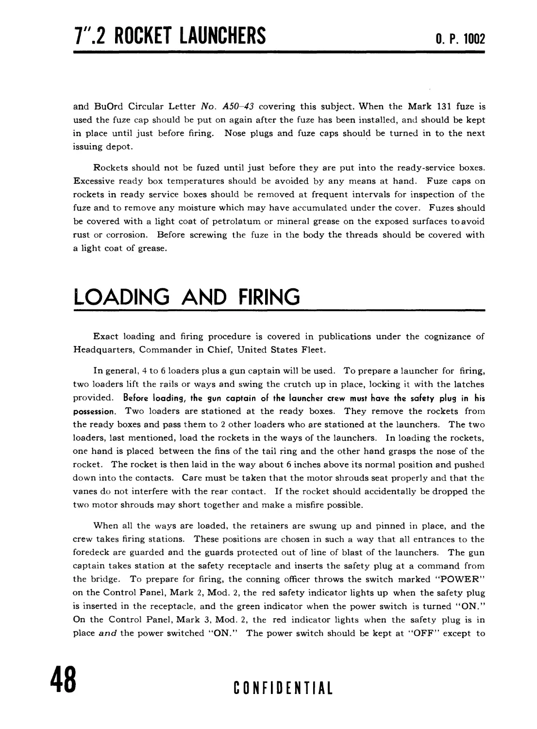
In general, 4 to 6 loaders plus a gun captain will be used. To prepare a launcher for firing,
two loaders lift the rails or ways and swing the crutch up in place, locking it with the latches
provided. Before loading, the gun captain of the launcher crew must have the safety plug in his
possession. Two loaders are stationed at the ready boxes. They remove the rockets from
the ready boxes and pass them to 2 other loaders who are stationed at the launchers. The two
loaders, last mentioned, load the rockets in the ways of the launchers. In loading the rockets,
one hand is placed between the fins of the tail ring and the other hand grasps the nose of the
rocket. The rocket is then laid in the way about 6 inches above its normal position and pushed
down into the contacts. Care must be taken that the motor shrouds seat properly and that the
vanes do not interfere with the rear contact. If the rocket should accidentally be dropped the
two motor shrouds may short together and make a misfire possible.
When all the ways are loaded, the retainers are swung up and pinned in place, and the
crew takes firing stations. These positions are chosen in such a way that all entrances to the
foredeck are guarded and the guards protected out of line of blast of the launchers. The gun
captain takes station at the safety receptacle and inserts the safety plug at a command from
the bridge. To prepare for firing, the conning officer throws the switch marked “POWER”
on the Control Panel, Mark 2, Mod. 2, the red safety indicator lights up when the safety plug
is inserted in the receptacle, and the green indicator when the power switch is turned “ON.”
On the Control Panel, Mark 3, Mod. 2, the red indicator lights when the safety plug is in
place and the power switched “ON.” The power switch should be kept at “OFF” except to
48
CONFIDENTIAL
OPERATION
О. P. 1002
check for readiness or to fire. To fire both launchers, the switches marked “port” and “star-
board” are thrown to the “ON” position. When the proper range is reached, the conning
officer presses the firing button at the next instant that the ship is on even keel. The firing
button should be kept depressed until all the rockets have gone; unless the battery is in good
condition, there may be a relatively large interval between the firing of the halves of a salvo.
As soon os the salvo is gone, the safety plug must be removed and the power switch opened. The laun-
chers can then be reloaded.
The ready boxes are replenished from storage as soon as possible, in any time available
between salvos. It should be noted that certain rockets have safety shorting wires shorting
the connection in the motor. These wires are to be clipped off close to the terminals before
the rockets are placed in the ready boxes. With ammunition of present and future issue, a
safety clip will be used instead of wires. This clip must be removed after the ammunition
has been loaded on the ways.
SAFETY PRECAUTIONS
It should be emphasized that all rocket ammunition must be treated with care. Rocket
motors should not be needlessly exposed to the direct rays of the sun or to any temperature in
excess of that printed on the motor tube, as such exposure may result in the rocket motor
blowing up on the launcher when the rocket is fired. Under no circumstances are rockets to
be fired when they have been subjected to a temperature in excess of the safe firing limitations
until they have been allowed to return to a temperature within the safe limits. Ammunition
which has been exposed to excessive temperatures (temperatures in excess of the upper limit
or less than the lower limit printed on the tube) should be maintained within the safe firing
limits for at least 6 hours before use. Every effort should be made to maintain ammunition
in ready service within the safe temperature firing limits at all times.
Since, at present, the propellant is sealed into the motor tube by means of closure discs
and asphalt paint, it is not possible to conduct visual or surveillance tests of any kind. The
development of surveillance tests for ballistite is at present being undertaken and when a proper
procedure has been worked out it will be made the subject of a publication. Under no circum-
stance is the propellant to be removed from the motor of any rocket. Any rocket motors on
hand in which the closure disc or discs have become loosened must not be fired. They must be
disposed of either by turning in to an ammunition depot or, if this is not practicable, by dump-
ing into deep water.
It is obvious that it is dangerous to stay directly in front of a launcher while it is loaded or
being loaded. It is more dangerous, however, to stay directly behind the launcher under the same
CONFIDENTIAL
49
7/ 2 ROCKET LAUNCHERS
О. P. 1002
circumstances. The blast that is emitted from the nozzle (rear) end is intensely hot and the
gases travel at a rate of between six and seven thousand feet per second. Small slivers of
burning powder may be blown out of the nozzle, and these are very difficult to extinguish.
Extreme caution must be taken to make sure that no one is directly in front of or directly to the rear of a
loaded launcher or one that is being loaded. Loading should always be done in such a manner
that the loader and any member of the crew are well to one side of the path that the projectile
or the blast would take in case a rocket should be fired either accidentally or intentionally.
Carelessness in this respect has resulted in fatal casualties.
All rocket launchers are equipped with safety plugs and receptacles. These receptacles
are installed on an external bulkhead, in sight of the launcher and at a safe distance therefrom,
and are part of the electrical firing circuit. The safety plug is at all times to be in the
possession or under the control of a particular person, whose responsibility it shall be to see
that the safety plug is not installed in the receptacle until the launcher is in all other respects
ready to be fired, and is removed immediately after firing. The safety plug shall be removed
by the person charged with its care before a loaded or partially loaded launcher with the plug in
place is approached by any other person. All personnel must be instructed not to load any
launcher or to approach any loaded launcher until it has been made absolutely certain that the
safety plug is in the possession of the crew member charged with its care. Fatal casualties
have resulted from failure to observe the necessary precautions.
Tests of firing circuits of launchers, Marks 20 and 22, when they involve personnel being in the
immediate vicinity of the launchers shall not be conducted until all rockets have been removed from
the launchers and the immediate vicinity of the launchers or stored in the ready-service box. Subse-
quent to the completion of such tests, the rockets may be reloaded on the launchers only at the order of
an individual at the launchers who has been made responsible for the loading operation and is in
actual physical possession of the safety plug.
The safety precaution in the preceding paragraph shall be posted conspicuously and
personnel concerned frequently and thoroughly instructed and drilled in it.
The projectiles should be kept free from rust, and the unpainted surfaces protected with
grease. The condition of the insulation should be periodically inspected, but no electrical
tests should be made because of the danger of setting off the electric primer. It is important
that it be stored and handled in such a way as to avoid bending of the tail rings, since distortion
of these rings may cause misfires due to lack of contact in the launcher, and will also have a
serious effect on the underwater trajectory.
It may sometimes happen that a misfire occurs and one or more rockets in a salvo will
remain on the ways. No one is to be allowed on the forecastle for at least 10 minutes after
such a misfire. Before approaching the launcher, which should be done from one side if possible,
make sure that the safety plug has been removed from the safety receptacle. If inspection then re-
veals that the closure disc in the nozzle has not been blown out, it is probable that the igniter
50
CONFIDENTIAL
OPERATION
О. P. 1002
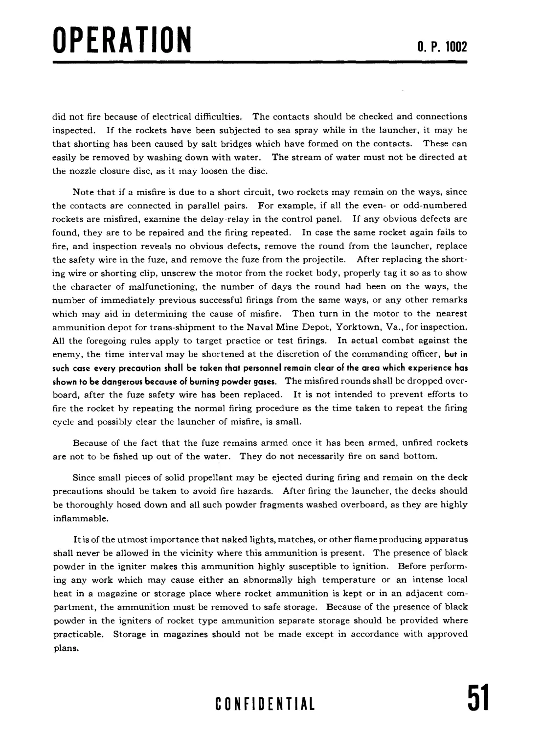
did not fire because of electrical difficulties. The contacts should be checked and connections
inspected. If the rockets have been subjected to sea spray while in the launcher, it may be
that shorting has been caused by salt bridges which have formed on the contacts. These can
easily be removed by washing down with water. The stream of water must not be directed at
the nozzle closure disc, as it may loosen the disc.
Note that if a misfire is due to a short circuit, two rockets may remain on the ways, since
the contacts are connected in parallel pairs. For example, if all the even- or odd-numbered
rockets are misfired, examine the delay-relay in the control panel. If any obvious defects are
found, they are to be repaired and the firing repeated. In case the same rocket again fails to
fire, and inspection reveals no obvious defects, remove the round from the launcher, replace
the safety wire in the fuze, and remove the fuze from the projectile. After replacing the short-
ing wire or shorting clip, unscrew the motor from the rocket body, properly tag it so as to show
the character of malfunctioning, the number of days the round had been on the ways, the
number of immediately previous successful firings from the same ways, or any other remarks
which may aid in determining the cause of misfire. Then turn in the motor to the nearest
ammunition depot for trans-shipment to the Naval Mine Depot, Yorktown, Va., for inspection.
All the foregoing rules apply to target practice or test firings. In actual combat against the
enemy, the time interval may be shortened at the discretion of the commanding officer, but in
such case every precaution shall be taken that personnel remain clear of the area which experience has
shown to be dangerous because of burning powder gases. The misfired rounds shall be dropped over-
board, after the fuze safety wire has been replaced. It is not intended to prevent efforts to
fire the rocket by repeating the normal firing procedure as the time taken to repeat the firing
cycle and possibly clear the launcher of misfire, is small.
Because of the fact that the fuze remains armed once it has been armed, unfired rockets
are not to be fished up out of the water. They do not necessarily fire on sand bottom.
Since small pieces of solid propellant may be ejected during firing and remain on the deck
precautions should be taken to avoid fire hazards. After firing the launcher, the decks should
be thoroughly hosed down and all such powder fragments washed overboard, as they are highly
inflammable.
It is of the utmost importance that naked lights, matches, or other flame producing apparatus
shall never be allowed in the vicinity where this ammunition is present. The presence of black
powder in the igniter makes this ammunition highly susceptible to ignition. Before perform-
ing any work which may cause either an abnormally high temperature or an intense local
heat in a magazine or storage place where rocket ammunition is kept or in an adjacent com-
partment, the ammunition must be removed to safe storage. Because of the presence of black
powder in the igniters of rocket type ammunition separate storage should be provided where
practicable. Storage in magazines should not be made except in accordance with approved
plans.
CONFIDENTIAL
51
7 ".2 ROCKET LAUNCHERS
О. P. 1002
MAINTENANCE
The launcher units should be kept painted and free from rust, dirt and accumulations
of salt. The electrical system should be examined at frequent intervals to insure that the
batteries, firing panel, contacts, safety plug and receptacle and wiring are in satisfactory con-
dition. Under no condition should the electrical system be checked when rockets are on the
launcher rails or when in an exposed condition in the immediate vicinity of the launcher. A simple
test of the electrical system is outlined below:
(a) With all switches in the OFF position measure the voltage at the battery.
(b) With the launcher unloaded place the power switch at ON and the starboard (or upper)
switch at ON. Insert the safety plug into its receptacle. Measure the voltage between the
hot knife edge contact and ground. A reading appreciably less than that obtained under
(a) indicates a short circuit or low resistance parts, which should be found and corrected.
If both voltage readings (a) and (b) are substantially the same, connect a suitable resistance
between the knife edge contact and ground; a convenient resistance consists of a 6-volt 21
cp or 32 cp automobile type lamp, passing about 4 and 6 amperes, respectively. Such a
lamp should light up fairly brightly; a quick check with a voltmeter should show at least 3
volts across the lamp. To avoid running the battery down these tests should be of as short
duration as possible.
(c) Repeat (b) with power switch at ON; and the port (or lower) switch at ON.
(d) All terminal tubes, glands, boxes, fittings, etc., exposed to salt spray should be kept
tight, gaskets and packing being used as necessary. Unless this is done water may enter into
one of the electric cables, which will act as a hose, providing a channel whereby water may
pass into connection boxes, etc., both above and below decks.
(e) Remove the covers of all boxes at frequent intervals. If moisture is present ascertain
and remove means of entry. Wash out the box with fresh water and dry.
(f) Do not use ordinary paint on the knife edge contact assembly, particularly on the
insulation. If necessary use an approved insulating varnish; in general the application of
varnish will not materially improve performance.
(g) Salt bridges may form on exposed parts causing short circuits and misfires. In gen-
eral, a thorough hosing with fresh, or even sea water, should remove them.
Each ship may carry a spare safety plug and one spare battery. Additional batteries
may be obtained from tenders or Navy Yards.
If ice forms on the launchers, including the contacts, it must be completely removed
before firing. If loaded, care must be taken to insure that the rockets are not frozen to the
ways. Extreme care must be taken that the fuzes are not armed during the de-icing process,
particularly when using a hose.
TACTICAL OPERATION
Tactical employment of the launcher, Mark 20, including the several corrections which
must be determined and included in the proper firing range, will be found in a publication
issued by Headquarters, Commander in Chief, United States Fleet.
52
CONFIDENTIAL
PERFORMANCE
О. P. 1002
Chapter 4
PERFORMANCE DATA OF
Г.2 ROCKET LAUNCHER, MARK 20
As has been previously mentioned, the propellant grain burns
with an almost constant pressure for several tenths of a second.
The value of the pressure depends on temperature, varying
from about 800 pounds per square inch at 10° F., and 1,500
pounds per square inch at 70° F., to 2,300 pounds per square
inch at 120° F. Since the motor tube is tested to 5,000 pounds
per square inch, ample safety factor is provided. The time of
burning depends inversely on the temperature, varying from
0.7 seconds to 0.2 seconds.
PERFORMANCE
CONFIDENTIAL
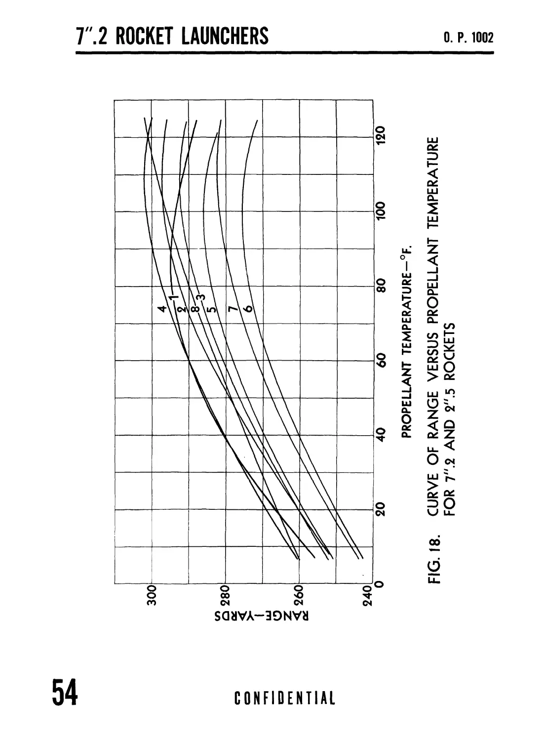
FIG. 18. CURVE OF RANGE VERSUS PROPELLANT TEMPERATURE
FOR 7".2 AND 2".5 ROCKETS
.2 ROCKET LAUNCHERS o p. 1002
PERFORMANCE
О. P. 1002
A graph, figure 18, shows the relationship between range and propellant
temperature. The variation of velocity and range with temperature depends
on a number of factors. At low temperature, the effective velocity of the gas
escaping from the nozzle is lowered because of the lower burning pressure.
Also, more energy must be used to heat the powder mass to the burning temper-
ature, leaving less for propulsion. Further,the acceleration distance is greater
at low temperature, resulting in more curvature in this part of the trajectory
and hence in shorter range. The combination of these effects results in a
decrease in velocity of about 10 percent, in range of about 20 percent, in going
from 70° F. to 10° F. At elevated temperatures, decrease in mechanical strength
of the powder results in an increased loss of powder in unburned form, prac-
tically compensating for effects tending to increase the range. Thus the range
is sensibly constant from 70° F. to 120° F. Because of the relatively low
velocities, the ranges will only be about 3 percent shorter than those calculated
for vacuum.
A range correction for complete round assemblies which differ in weight
from the nominal round weight of page 44, may be made by the following rule:
The percentage change in range is twice the percentage change in weight,
and in the opposite direction, i. e., an increase in weight causes a decrease in
range and vice versa.
CONFIDENTIAL
55
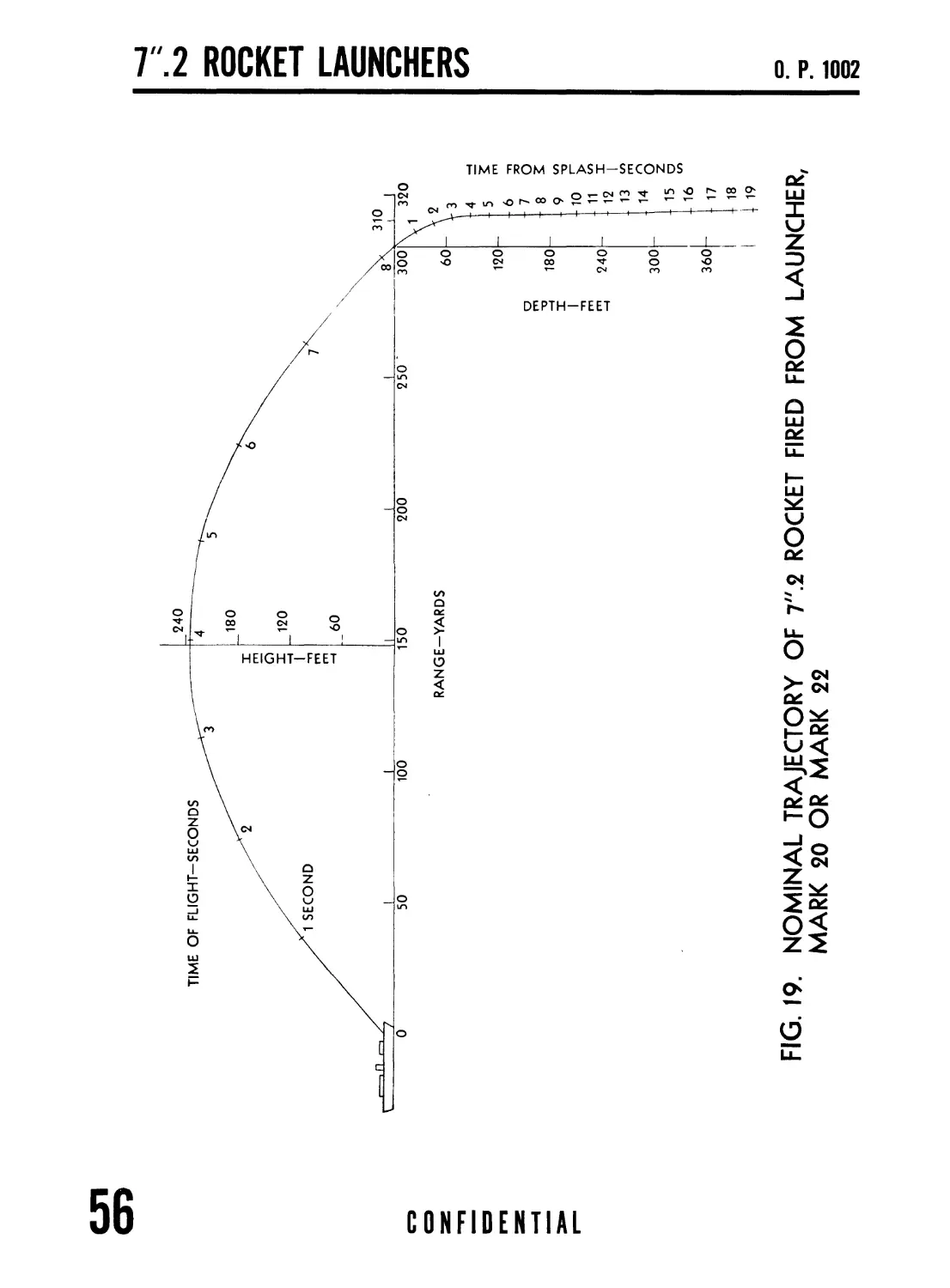
FIG. 19. NOMINAL TRAJECTORY OF 7".2 ROCKET FIRED FROM LAUNCHER,
MARK 20 OR MARK 22
1ЧЭ
PERFORMANCE
О. P. 1002
Since the point of application of thrust of the rocket motor is behind the center of gravity
of the charge, there may be some tendency to veer off course when the acceleration continues
beyond the launcher. For this reason, the lateral dispersion of shots from a given way may
depend quite markedly on the burning time, and hence on the temperature. For example, at
120° F., about one-fifth of the burning occurs on the ways and the lateral dispersion is approx-
imately 2 yards in 300. At normal temperatures, one-tenth of the burning is on the ways and
the dispersion is approximately 4 yards. At 10° F., the fraction is one-thirteenth and the
dispersion approximately 12 yards. The dispersion in range, on the other hand, is nearly
constant, about 6 yards in 300, since at 49° quadrant angle, the range is not sensitive to the
angle of the trajectory at the end of burning.
In cold weather, due to slower burning time of propellant grain, a strong cross wind
causes notable deflection errors. For example, at 25° F., a 20 mile per hour cross wind produces
a 25 yard deflection into the wind. At 70° F. or higher, the corresponding error is 5 yards or
less. The error into the wind is proportional to the cross range component of wind velocity.
It is recognized that pitch affects the range since the ways are in a displaced position and
the charges have an upward or downward component depending on the direction of the pitch.
However, the amount of this variation in range is not sufficient to make corrections worth-
while. Also the roll of the ship results in an error in train. Thus firing should be done when
the ship is on an even keel. Another quantity which has a bearing on the trajectory of the
rocket is the forward speed of the boat.
In the first 2 or 3 feet after striking the water, the rocket continues on its former
path, but with a large deceleration of the order of 50 to 100 times gravity. In about 30 feet
of travel, the rocket is brought to a vertical course and proceeds downward with its terminal
velocity of 22 to 25 ft./sec. To reach 100 foot depth takes 12.5 seconds, including 8 seconds
flight in air. (See fig. 19.) In order to keep the rocket on course under water, it is given
a spin by the vanes on the motor. Near the end of the air trajectory, the rockets make about
four revolutions per second and one revolution in 40 feet. Just under the surface, the rate
of spin is approximately one turn in 6 feet, probably decreasing to about one in 12 at
greater depths.
Until further notice is given, this ammunition must not be used if the propellant
temperature is higher than 120° F.z or lower than 10°F. At temperatures higher
than 120° F., burning of the propellant grain is greatly accelerated with a
dangerous increase in pressure. At temperatures lower than 10° F., burning
may be incomplete and large unburned pieces of powder may be ejected from
the nozzle. Also misfires may result.
CONFIDENTIAL
57
CONFIDENTIAL
Column Number: (For applicable assemblies see pages 44 and 45) Propellant Tempera- ture (°F.) 10
1 70 120 2 10 3 70 120
10 70 i 120
Time of burning_-(sec.) Velocity at end of burning (f. s.) Range at 49° eleva- tion (yd.) Time of flight (sec.) Mean lateral devi- ation (yd.) Mean range deviation (yd.) 0.70 154 258 7.5 11 6 0.34 169 293 8.0 4 5 0.24 168 289 7.9 2 2 143 253 6.6 11 5 I 0.44 I 164 289 7.5 6 4 0.29 167 296 7.5 2 3 0.59 153 254 6.8 9 5 0.40 166 285 7.4 6 5 0.26 170 291 7.8 3 7
Vertical component of underwater velocity (f. s.) From 0 to 25s ft. depth From 25 to 50 ft. depth From 50 to 100 ft. depth BelowWO ft. depth 30.6 15.3 21.9 23.1 32.7 16.3 23.5 24.7 32.2 16.1 23.1 24.3
Time from splash (sec.) To 25 ft. depth.- To 50 ft. depth-- To 100 ft. depth-. To 200 ft. depth-- To 300 ft. depth - To 400 ft. depth-- 0.8 2.5 4.7 9.1 13.4 17.7 0.8 2.3 4.4 8.5 12.5 16.6 0.8 2.3 4.5 8.6 12.7 16.8
Forward travel beyond splash (ft.) At 25 ft. depth-- At 50 ft. depth _ At 100 ft. depth-- Below 1 00 ft. depth 20 24 26 26 20 24 26 26 14 17 19 22
7".2 ASSEMBLIES 2".5 ASSEMBLIES
4 5 6 7 8
1 10 I 70 i 120 10 70 120 10 70 120 10 70 120 I I I 10 70 120
0.59 0.40 0.26 0.59 0.40 0.26 0.29 0.1610 11
155 i 168 173 I 150 163 167 162 172 178
1 263,294 301 253 281 283 245 271 273 246 275 282 262 286 301
6.9 7.5 7.9 _ ___ _ 6.7 7.3 7.7 7.3 7 6 7 8
9 6 3 7 3 2 7 3 2 9 6 3 7 3 1
5 5 7 5 5 1 7 8 7 6
39.3 37.1 37.7 32.7 35.5
15.7 14.9 15.1 16.3 18.7
21.5 20.3 20.6 23.4 27.4
22.4 21.1 21.5 24.7 28.4
0.6 0.7 0.7 0.8 0.7
2.2 2.4 2.3 2.3 2.0
4.6 4.8 4.7 4.4 3.9
9.0 9.5 9.4 8.5 7.4
13.5 14.3 14.0 12.5 10.9
17.9 19.0 18.7 16.6 14.4
14 14 14 14 15
17 17 17 17 22
19 19 19 19 27
22 22 22 22 27
ьо
PERFORMANCE
О. P. 1002
SPREAD-YARDS
ROCKETS APPROXIMATELY
11.8 YARDS APART
ON LANDING
FIG. 20. PATTERN OF FIRE
CONFIDENTIAL
59
COGNIZANCE
О. P. 1002
Chapter 5
COGNIZANCE
The Bureau of Ordnance will supply and retain cognizance over the following items of
equipment:
A 7".2 Rocket Launcher, Mark 20.
В Control panel, Mark 2, Mod. 2, or Mark 3 or Mark 3, Mod. 2, or control
panel, Mark 7, when furnished.
C Safety plug and receptacle.
D Wiring from launcher to branch box “E” type.
E Ammunition and fuzes.
F Fuze wrenches.
G Batteries.
The Bureau of Ships will supply and retain cognizance over the following items of equip-
ment :
A Foundations for the launchers, including means for securing the launchers
thereto.
В All steel sheathing or other material used for deck protection.
C Watertight metallic stowage lockers for ready-service ammunition.
D Magazine stowage for fuze containers.
E Magazine stowage for assembled rockets (unfuzed).
F All wiring and electrical appurtenances (except safety plug and receptacle)
for connecting the launchers to the control panel.
G Such communication or signal facilities as may be authorized in order that the
firing station may maintain proper contact with personnel at the launchers.
CONFIDENTIAL
61
Т.2 ROCKET LAUNCHERS
О. P. 1002
FIG. 21. 7".2 ROCKET LAUNCHER, MARK 22, LOADED, READY
FOR FIRING
62
CONFIDENTIAL
INTRODUCTION
О. P. 1002
Chapter 6
T.2 ROCKET LAUNCHER, MARK 22
DEFINITION
The 7".2 Rocket Launcher, Mark 22, is a rocket-launching de-
vice similar to the launcher, Mark 20, but consisting of two hinged
sets of steel ways instead of one set, as is the case with the Mark 20.
This launcher was formerly known as the Projector, Mark 22,
and many name plates are so marked.
The designation Control Panel was changed to Firing Panel
subsequent to the preparation of this ordnance pamphlet.
LAUNCHER
MARK 22
USE
The launcher, Mark 22, is used exactly the same as the Mark
20. Each launcher, Mark 22, fires 8 rockets in a salvo.
CONFIDENTIAL
63
Т.2 ROCKET LAUNCHERS
О. P. 1002
FIG. 22. 7".2 ROCKET LAUNCHER, MARK 22, IN STOWED
POSITION
64
CONFIDENTIAL
DESCRIPTION
О. P. 1002
7".2 ROCKET LAUNCHER, MARK 22
The launcher consists of 2 sets of steel ways. Each set of ways is
hinged to the base frame and is independently supported in the raised
position by its own crutch. The ways themselves consist of sections of
steel plate bent up to make rails in which the rockets ride. The three
inside sections are made broad and wedge-shaped, one piece thus serving
as common way for two adjacent rockets. A spread of one part in 40
is made between ways to give the required spacing of shots. A set of
retractible retainers is provided for each set of 4 ways to keep the rockets
from being washed out of place. In general, the same protection against
blast must be provided as is provided for the Launcher, Mark 20. It
should be noted that the deck plate is not a part of the launcher, Mark 22
as it is with the Launcher, Mark 20.
The launcher is designed to fold down and be lashed to the deck when
not in use, as shown in figure 22. When conditions require it, weather
permitting, the launcher may be maintained elevated and loaded. When-
ever weather conditions are such that the launchers or the ammunition
exposed on the rails would be subject to damage or deterioration, the
ammunition should be unloaded and stowed and the rails lowered and
lashed down.
CONFIDENTIAL
65
Т.2 ROCKET LAUNCHERS
О. P. 1002
STEEL DECK SHEATHING
READY SERVICE
AMMUNITION BOXES
LAUNCHER IN STOWED POSITION
PORT LAUNCHER
PILOT HOUSE
STEEL SHEATHING
ON BREAKWATER
STARBOARD LAUNCHER
FIVE WIRE CABLE
SAFETY RECEPTACLE
CONTROL PANEL
FIVE WIRE
CONNECTION BOX
FIG. 23. FOREDECK INSTALLATION OF 7".2 ROCKET
LAUNCHER, MARK 22
66
CONFIDENTIAL
DESCRIPTION
О. Г. 1002
INSTALLATION
For mounting the launchers, two clear spaces about 42 inches
by 108 inches are required on the foredeck. A 16-inch or less
portion of the forward end of the lower launcher ways may be cut
off only if installation requires it. The same type of blast deflector
plates are used for the Launcher, Mark 22, as have been described
on Page 15. In addition, the portion of the deck between the
upper and lower set of ways and immediately behind the upper set
of ways is sheathed against blasts.
The launchers are mounted on wood or metal foundations so
that they are level athwartships and have a 3°-5° slope fore and
aft with the high point forward. The two launchers are placed,
in the folded position, on the foredeck symmetrically about the
centerline of the ship. The extreme forward point of the inboard
edge of the base of each launcher deviates 5 И to 6% inches
further from the centerline than the aft end of the base. This
deviation is inversely proportional to the distance between
launchers. This placement of the launchers gives an approxi-
mately equal spacing to all eight rockets.
Ready-service boxes are provided on the foredeck, convenient
to the launchers, for ready ammunition. Each box holds the
rounds in easily accessible racks and is watertight. Additional
ammunition may be stowed below decks in magazine stowage.
CONFIDENTIAL
67
Т.2 ROCKET LAUNCHERS
О. P. 1002
FIG. 24. ELECTRICAL CONTACTS FOR 7".2 ROCKET LAUNCHER,
MARK 22
68
CONFIDENTIAL
DESCRIPTION
0. Г. 1002
ELECTRICAL CONTROLS
Firing is electrical and is controlled from the bridge.
Electrical contact for firing is made to the motor shrouds of the rocket
by means of knife edges as in Launcher, Mark 20. The lower contact
mounted in the deflector plate grips the inside of the grounded rear motor
shroud which is electrically connected to one side of the igniter and
serves as a stop. The upper insulated contact is mounted on a phosphor-
bronze spring and bears on the outside of the forward shroud. Both
contacts are made of hardened stainless steel.
The wiring to the safety plug is the same as described for the Launcher,
Mark 20. The safety plug is carried by the gun captain and it is his responsi-
bility to see that the plug is not inserted in the safety receptacle until all
personnel is off the foredeck, after the launchers have been loaded.
ELECTRICAL
CONTROLS
CONFIDENTIAL
69
Т.2 ROCKET LAUNCHERS
О. P. 1002
THIS NAME PLATE
USED ON FIRING
PANEL MARK 3,MOD.1
AND MARK 3Z MOD. 3
FIRING BUTTON
CONTROL PANEL MARK 3
AND MARK 3, MOD. 2
FIG. 25. CONTROL
MARK 22
PANEL FOR 7".2 ROCKET LAUNCHER,
70
CONFIDENTIAL
DESCRIPTION
О P. 1002
FIRING PANELS
The Control Panels, Mark 3, Mod. 1, or Mark 3, Mod. 3, are used
with the Launcher, Mark 22. The Control Panel, Mark 3, Mod. 1 utilizes
one 45-volt and two б-volt dry batteries. (The 45-volt battery is now
known to be unsuitable). The Control Panel, Mark 3, Mod. 3 utilizes
two 71/2-volt dry batteries. Control Panels, Mark 3, Mod. 1 and Mark
3, Mod. 3 are identical to the Control Panels, Mark 3 and Mark 3, Mod.
2, respectively, except that the name-plate is changed. In the Control
Panels, Mark 3 and Mark 3, Mod. 2, the plate reads “Port-Power-Star-
board.” In the Control Panels, Mark 3, Mod. 1 and Mark 3, Mod. 3, the
plate reads “Upper-Power-Lower.’’ (See fig. 25.)
When the switch marked “UPPER’’ is operated and the projectors
are fired, the odd-numbered upper ways of both port and starboard
launchers fire together. When the switch marked “LOWER’’ is operated
and the launchers are fired, the same sequence as described above is
repeated for the lower ways, both port and starboard.
A detailed description of the rocket is given in chapter 2 of this
pamphlet. Views of the rocket and fuzes are shown in the illustrations
mentioned in this chapter.
CONFIDENTIAL
71
7".2 ROCKET LAUNCHERS
О. P. 1002
FIG. 26. WIRING DIAGRAM FOR 7".2 ROCKET LAUNCHER,
MARK 22
(USING CONTROL PANEL, MARK 3, MOD. 1 OR MARK 3, MOD. 3)
WIRING DIAGRAMS
Wiring diagrams for the launcher, Mark 22, are shown in figures 26 A and B. Figure
26A shows the wiring of Control Panel, Mark 3, Mod. 1 and figure 26B shows the wiring of
Control Panel, Mark 3, Mod. 3.
72
CONFIDENTIAL
DESCRIPTION
О. P. 1002
FIG. 27. CIRCUIT SCHEMATIC FOR 7".2 ROCKET LAUNCHER,
MARK 22
(USING CONTROL PANEL, MARK 3, MOD. 3)
CIRCUIT SCHEMATIC
A Circuit Schematic for the Launcher, Mark 22, using Control Panel, Mark 3, Mod. 3,
is shown in figure 27.
CONFIDENTIAL
73
OPERATION
О. P. 1002
Chapter 7
OPERATION AND MAINTENANCE
7".2 ROCKET LAUNCHER, MARK 22
LOADING AND FIRING
Exact loading and firing procedure will be covered in publications from other sources.
To prepare a launcher for firing, two loaders lift the upper set of ways and swing its crutch
up in place, locking it with the latches provided. They then raise the lower set of ways and
swing its crutch up in place and lock it with the latches provided. Before loading, the gun
captain of the launcher crew must have the safety plug in his possession. Two loaders are stationed
at the ready boxes. They remove the rockets from the ready boxes and pass them to two other
loaders, who are stationed at the launchers. The two loaders, last mentioned load the rockets
in the ways of the launchers. In loading the rockets, one hand is placed between the fins of
the tail ring and the other hand grasps the nose of the rocket. The rocket is then laid in the
way about 6 inches above its normal position and pushed down into the contacts. Care must
be taken that the motor shrouds seat properly and that the vanes do not interfere with the
rear contact. After the shroud of the motor has been placed in contact with the knife edges,
the safety clip should be removed if this has not been done previously. The rocket should not
be dropped on the motor as a hard blow may cause the two shrouds to short together and
make a misfire possible.
OPERATION
CONFIDENTIAL
75
OPERATION
О. P. 1002
MAINTENANCE
The maintenance instructions of page 52 of this pamphlet apply also
to the Launcher, Mark 22.
ROCKET PERFORMANCE
The rocket for the Launcher, Mark 22, is exactly the same as the
rocket for the Launcher, Mark 20. Therefore, the performance data
given on pages 53 through 58 will apply.
CONFIDENTIAL
77
COGNIZANCE
О. P. 1002
Chapter 8
COGNIZANCE
The Bureau of Ordnance will supply and retain cognizance over the following items of
equipment:
A 7 ".2 Rocket Launcher, Mark 22.
В Control Panel, Mark 3, Mod. 1 or Mark 3, Mod. 3, or Control Panel, Mark
7, when supplied.
C Safety plug and receptacle.
D Wiring from launcher to branch box “E” type.
E Ammunition and fuzes.
F Fuze wrenches.
G Batteries.
The Bureau of Ships will supply and retain cognizance over the following items of equip-
ment:
A Foundations for the launchers, including means for securing the launchers
thereto.
В All steel sheathing, including the steel deck plates in the area of the direct
blast.
C Watertight, metallic stowage lockers for ready-service ammunition.
D Magazine stowage for fuze containers.
E Magazine stowage for assembled rockets (unfuzed).
F All wiring and electrical appurtenances (except safety plug and receptacle)
for connecting the launchers to the control panel.
G Such communication or signal facilities as may be authorized in order that
the firing station may maintain proper contact with personnel at the
launchers.
CONFIDENTIAL
79
2".5 ROCKET LAUNCHER
О. P. 1002
FIG. 28. 7".2 ROCKET LAUNCHER, MARK 20, EQUIPPED WITH
2".5 ROCKET LAUNCHER AND LOADED WITH 2".5
ROCKETS
80
CONFIDENTIAL
INTRODUCTION
О. P. 1002
Chapter 9
2 ".5 ROCKET LAUNCHER AND 2 ".5 ROCKETS
FOR LAUNCHERS, MARKS 20 AND 22
DEFINITION
2".5 Rocket Launchers, Mark 4 are used as subcaliber attach-
ments on 7".2 Rocket Launchers, Mark 20 and Mark 22 to permit
the use of subcaliber ammunition for practice purposes.
USE
2".5 Rocket Launchers and 2".5 Rockets are used for training
crews in the use of launchers. 2".5 Rockets are used in practice
against target submarines and upon contact with the submarine
can be heard by the crews inside, thus enabling each hit to be
registered.
2B.5 LAUNCHER
CONFIDENTIAL
81
2".5 ROCKET LAUNCHER
О. P. 1002
POWDER GRAIN
IGNITER
INSULATED WIRES о
DESICCANT BAG
275 ROCKET
BODY MK. 1
BODY
CONTACT PLUG
l'.'25 ROCKET
MOTOR MK.1
SAFETY SHORT-
CIRCUITING WIRE
(TO BE REMOVED
ONLY WHEN ROCKET
IS READY FOR USE)
GRID
о NOZZLE RING
SHROUD
2?5 ROCKET BODY
MK. 1 MOD. 2
SECTION THROUGH ROCKET VIEW OF ASSEMBLED ROCKET
READY FOR USE EXCEPT FOR FIRING PIN ASSEMBLY REMOVED
REMOVAL OF SHORT-CIRCUITING WIRE
END VIEW
FIG. 29. 2".5 ROCKET (SUBCALIBER)
82
CONFIDENTIAL
AMMUNITION
О. P. 1002
THE 2",5 ROCKET
GENERAL:
The 2".5 Rocket is approximately 17 inches long and 2".5 in diameter at its widest point.
Performance data is given on pages 54 and 58.
INSTALLATION:
The 2".5 Rocket Launchers are installed between the adjacent rails of the 7".2 Rocket
launcher in such a way that the guide near the lower end of the 2".5 Launcher fits between the
ways of the 7".2 Launcher and the hook on the upper under side of the 2".5 Launcher lies for-
ward of the upper cross member of the 7".2 Launcher.
From this position the 2".5 Launcher is slid down until the lower end is in firm contact
with the ground contact on the 7".2 Launcher and the hook of the 2".5 Launcher has engaged
the upper cross member of the 7".2 Launcher way assembly. The electrical contact of the
2".5 Launcher should then be bearing on the insulated electrical contact point on the 7".2
Launcher. Care should be taken to insure that no part of the 2".5 Launcher other than the
electrical contact is bearing on the insulated electrical contact point of the 7".2 Launcher.
BODY:
The 2".5 Rocket Body, Mark 1 is approximately 6".6 long and 2".5 in diameter. The
after section of the body is ogival in shape and terminates in a base threaded internally to
engage the thread of the motor tube. The cavity in the nose of the body was originally pro-
vided to contain a shotgun shell which was fired when the rocket came in contact with the
hull of a submarine. As experience has proven the use of shotgun shells for such a purpose
to be unsatisfactory and unsafe for handling, future issues of 2".5 rockts will contain no explo-
sive charge in the body. Shotgun shells will not be used. A later development is the 2".5
Rocket Body, Mark 1, Mod. 2, which is approximately 6".27 long and 2".5 in diameter. It
has no cavity provided for any shotgun shell.
MOTOR:
The motor, fabricated of steel, consists of a tube having an external diameter of 1".25,
4 radial fins and a cylindrical shroud surrounding the fins. The forward end of the tube is
externally threaded for engaging the base of the body. The fins are inclined 5° relative to the
tube axis in order to impart a certain amount of “spin” to the rocket with the object of improv-
ing the travel of the rocket in water.
PROPELLANT COMPONENTS:
The propellant components are confined in the motor. A typical assembly of the com-
ponents is shown in figure 28. The main component is a single grain of extruded ballistite
powder with extruded ribs and a perforation through the center. At the forward end of
this powder grain is located an igniter which consists of an electrical squib leading to a charge
of black powder. Two insulated electrical wires are run from an electrical plug through the
powder grains to the igniter. When the electrical circuit is closed, the igniter burns, igniting
the propellant grain which burns uniformly on all surfaces. The gases evolved are forced out
through the nozzle at high velocity and by their reaction on the motor, propel the unit forward.
2".5 ROCKET
CONFIDENTIAL
2". 5 ROCKET LAUNCHER
О. P. 1002
LOADING AND FIRING
Before loading, the gun captain of the launcher crew must be in
possession of the safety plug. After the 2".5 Rocket Launchers
are in place on the 7 ".2 Launcher, the 2".5 Rockets are placed
in the launchers. The short circuiting wire or clip which con-
nects together the two prongs of the contact plug should then
be removed and the contact plug inserted in the receptacle.
As soon as this is done, the crew takes firing stations which are
chosen in such a way that all entrances to the foredeck are
guarded and the guards protected out of line of blast of the
launchers. The gun captain of the crew takes station at the
Safety Receptacle and inserts the safety plug on command of the
conning officer. From here on the firing procedure is exactly
the same as for live ammunition. As soon as the salvo is gone,
the safety plug must be removed and the power switch opened.
The launchers can then be reloaded.
84
CONFIDENTIAL
OPERATION
O. F. 1002
SAFETY PRECAUTIONS
It should be emphasized that although the rocket body is inert, the
ballistite powder in the motor can blow up at elevated temperatures
above 120° F. Also, the blast from the motor is extremely intense.
Consequently, when using the 2".5 Rockets, the same safety precautions should
be observed as are observed when using 7°.2 Rockets. Pages 47 through to
51 apply to 2".5 Rockets as well as to 7".2 Rockets.
COGNIZANCE
The Bureau of Ordnance will supply, and retain cognizance over the
following items of equipment (in addition to the items previously men-
tioned on page 61):
(a) 2" .5 Rocket Launchers (Subcaliber Ways).
(b) 2".5 Rockets.
CONFIDENTIAL
85
Т.2 ROCKET LAUNCHERS
О. P. 1002
DISTRIBUTION
Requests for OP 1002 1st. Revision, should be addressed to the nearest BuOrd Publications
Distribution Center:
Commandant and Superintendent,
U. S. Naval Gun Factory, Navy Yard,
Washington 25, D. C.
(Attn: OrdPubSubcen).
Commandant,
Navy Yard,
Mare Island, Calif.,
(Attn: OrdPubSubcen).
Commander Service Force, SEVENTH FLEET,
Ordnance Publications Subcenter,
c/o Fleet Post Office,
San Francisco, Calif.
Officer in Charge,
Ordnance Publications Subcenter,
Naval Supply Depot,
Pearl Harbor, T. H.
DISTRIBUTION:
Standard Navy Distribution List No. 18.
2 copies each unless otherwise noted.
1. a-e, g, h, к, 1, r-t, x, z, aa-ff, ii—11, nn, ss, tt, zz; 2. e-h, m, o, p, r-t, v, x; 3. c*, e*, k*,
1*, r*, y*, cc*, nn*, vv*, xx*, yy*; B3. (5 copies), LIONS, CUBS; E3.; 4. e*, g*, k*, p*,
r*-w*, gg*, mm*, oo*, pp*, qq*; 5. b (Alusna, London only); 6. (25 copies), a-p; 7.
f-j, o, p, s, u (except Naval Clothing Depot), x, ее; 7. (5 copies), 1; 7. (25 copies), b, c;
8.h (NOL and No. Beach only), i, j, 1, n (SPECIAL LIST G, K, L, Q, S, AA), hh; 8. (50
copies), b, n (10); 10. i (except Chicago), j, t; 10. (15 copies), i, (Chicago); 10. (25 copies),
nn; 11.a (BuShips, CNO, SecNav); 12.; 14.a; 14. (50 copies), s.
*Applicable ships
86
CONFIDENTIAL
16- 39136-1 U S GOVFRNMFNt PRINTING OFFICE