/


Tags: weapons military affairs
Year: 1941

Text
DEFENCE ST AIT
ORDNANCE DEPARTMENT
20 mm
ANTITANK -
RIFLE
L/39
HELSINKI 1941
Translated by Rohie Kulokivi
Finland - 1995
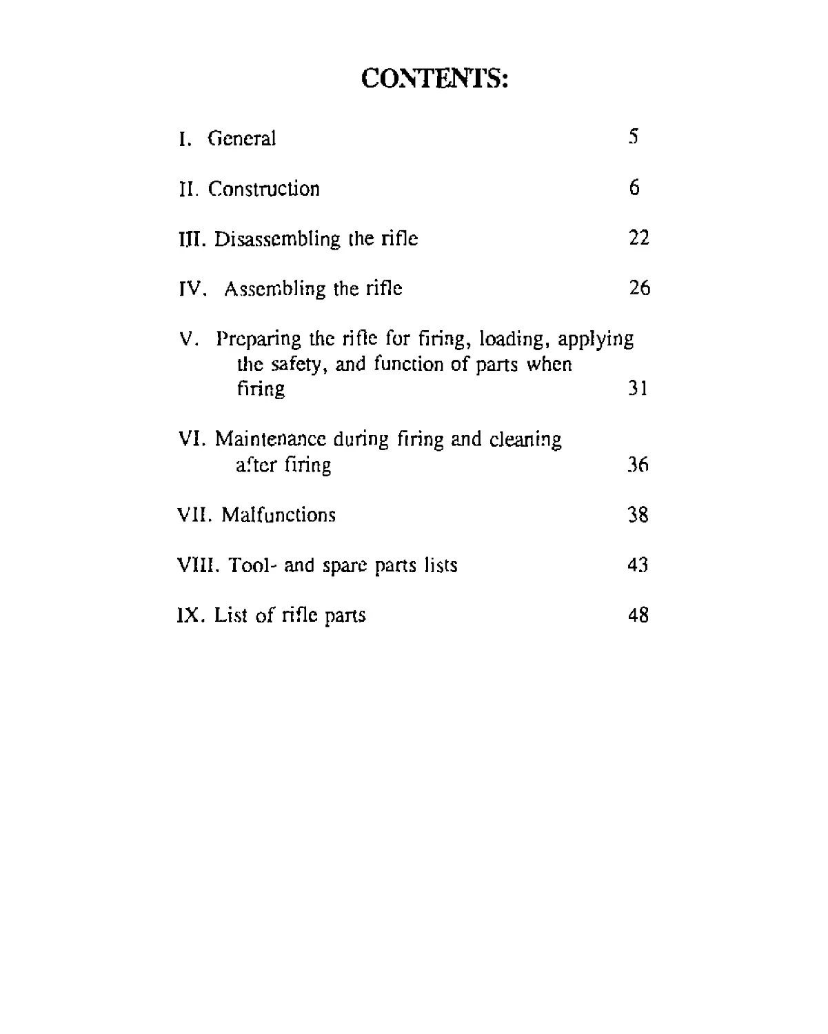
CONTENTS:
I. General 5
II. Construction 6
III. Disassembling the rifle 22
TV, Assembling the rifle 26
V. Preparing the rifle for firing, loading, applying
the safety, and function of parts when
firing 31
VI. Maintenance during firing and cleaning
after firing 36
VII. Malfunctions 38
VIII. Tool- and spare parts lists 43
IX. List of rifle parts
48
20 mm
ANTITANK -
RIFLE
L/39
20 mm AT. rifle L/39 is a self-loading(semiautomatic)
direct engagement weapon. Its armor penetration capability
with hit angle of 60 degrees is:
20 mm up to 300 m and
16 mm up to 500 m.
Firing at a straight angle increases the penetration
considerably.
I. GENERAL
Caliber
Gun weight without magazine
Total length of gun
Traverse possibility without turning
20 mm
49,5 kg
2 m
the bipod approximately
600 piiru
(Translation note: 360 degrees - 6000 piiru = 6400 mils)
6
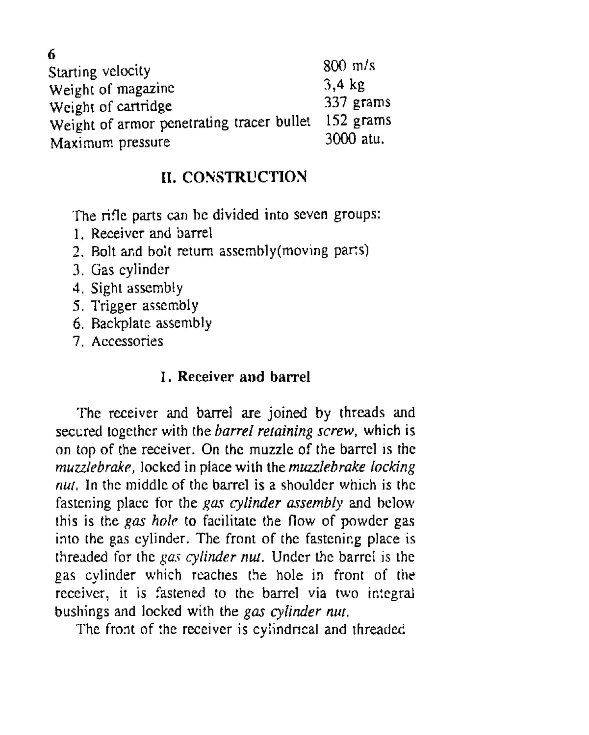
Starting velocity
Weight of magazine
Weight of cartridge
Weight of armor penetrating tracer bullet
Maximum pressure
800 m/s
3,4 kg
337 grams
152 grams
3000 atu.
II. CONSTRUCTION
The rifle parts can be divided into seven groups:
1. Receiver and barrel
2. Bolt and bolt return assembly(moving parts')
3. Gas cylinder
4. Sight assembly
5. Trigger assembly
6. Backplate assembly
7. Accessories
I. Receiver and barrel
The receiver and barrel are joined by threads and
secured together with the barrel retaining screw, which is
on top of the receiver. On the muzzle of the barrel is the
muzzlebrake, locked in place with the muzzlebrake locking
nut. In the middle of the barrel is a shoulder which is the
fastening place for the gas cylinder assembly and below
this is the gas hole to facilitate the flow of powder gas
into the gas cylinder. The front of the fastening place is
threaded for the gas cylinder nut. Under the barrel is the
gas cylinder which reaches the hole in front of the
receiver, it is fastened to the barrel via two integral
bushings and locked with the gas cylinder nut.
The front of the receiver is cylindrical and threaded
7
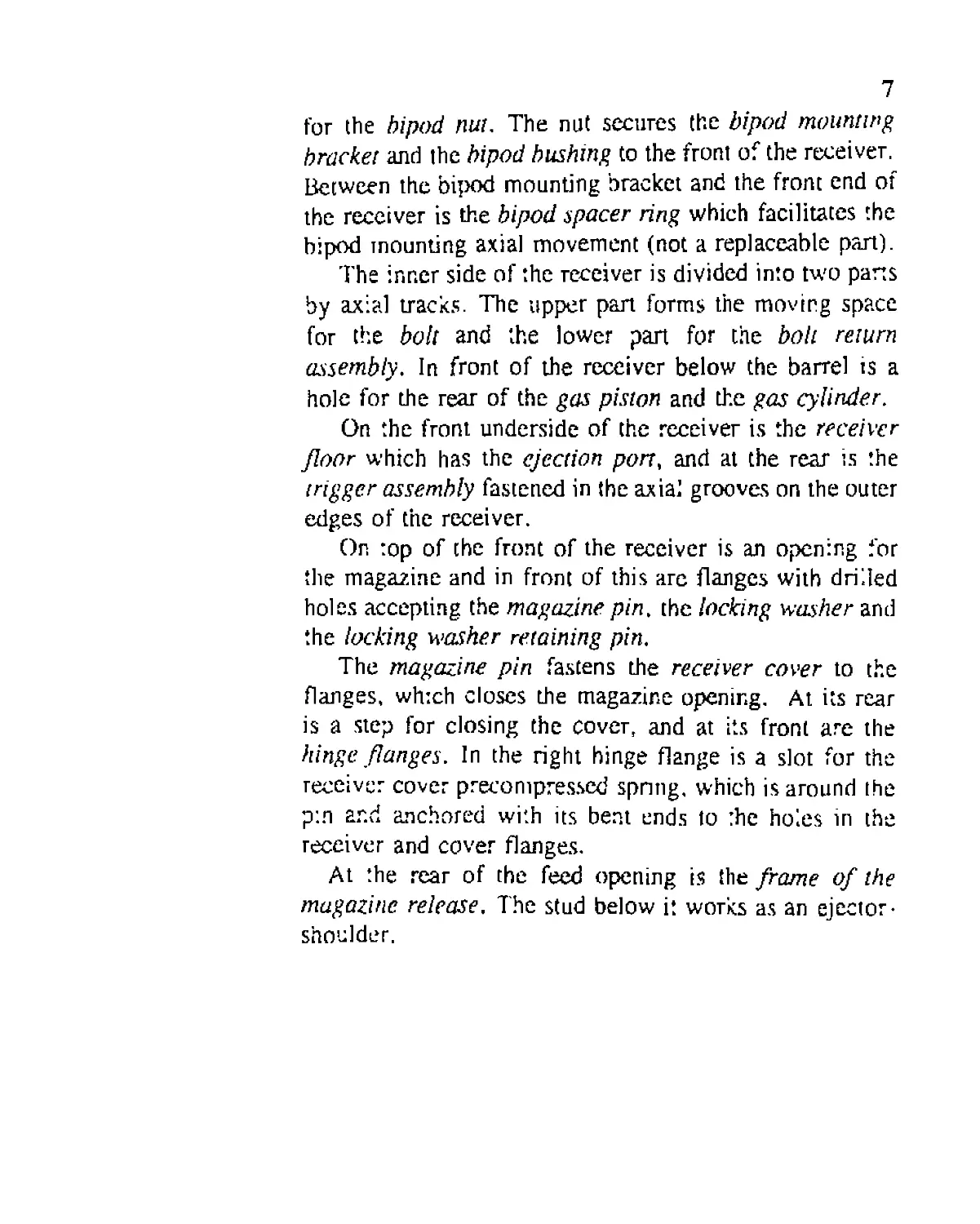
for the bipod nut. The nut secures the bipod mounting
bracket and the bipod bushing to the front of the receiver.
Between the bipod mounting bracket and the front end of
the receiver is the bipod spacer ring which facilitates the
bipod mounting axial movement (not a replaceable part).
The inner side of the receiver is divided into two parts
by axial tracks. The upper part forms the moving space
for the bolt and the lower part for the bolt return
assembly. In front of the receiver below the barrel ts a
hole for the rear of the gas piston and the gas cylinder.
On the front underside of the receiver is the receiver
floor which has the ejection port, and at the rear is the
trigger assembly fastened in the axial grooves on the outer
edges of the receiver.
On top of the front of the receiver is an opening for
the magazine and in front of this arc flanges with drilled
holes accepting the magazine pin. the locking washer and
the locking washer retaining pin.
The magazine pin fastens the receiver cover to the
flanges, whtch closes the magazine opening. At its rear
is a step for closing the cover, and at its front are the
hinge flanges. In the right hinge flange is a slot for the
receiver cover precompressed spring, which is around the
pin ar.d anchored with its bent ends to rhe holes in the
receiver and cover flanges.
At the rear of the feed opening is the frame of the
magazine release. The stud below it works as an ejector-
shoulder.
8
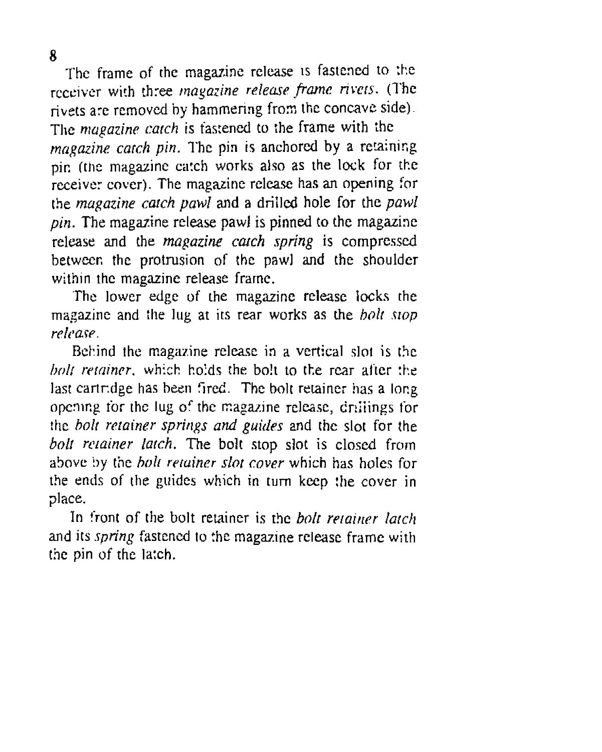
The frame of the magazine release is fastened to the
receiver with three magazine release frame rivets. (The
rivets are removed by hammering from the concave side).
The magazine catch is fastened to the frame with the
magazine catch pin. The pin is anchored by a retaining
pin (the magazine catch works also as the lock for the
receiver cover). The magazine release has an opening for
the magazine catch, pawl and a drilled hole for the pawl
pin. The magazine release pawl is pinned to the magazine
release and the magazine catch spring is compressed
between the protrusion of the paw] and the shoulder
within the magazine release frame.
The lower edge of the magazine release locks the
magazine and the lug at its rear works as the halt stop
release.
Behind the magazine release in a vertical slot is the
boll retainer, which holds the bolt to the rear after the
last cartridge has been fired. The bolt retainer has a long
opening for the lug or the magazine release, cnliings for
the bolt retainer springs and guides and the slot for the
boll retainer latch. The bolt stop slot is closed from
above by the boh retainer slot cover which has holes for
the ends of the guides which in turn keep the cover in
place.
In front of the bolt retainer is the bolt retainer latch
and its spring fastened to the magazine release frame with
the pin of the latch.
9
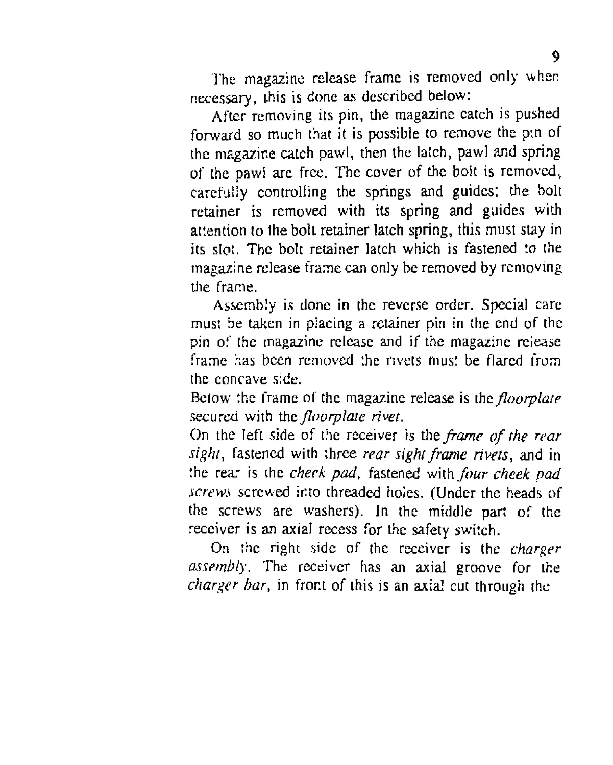
The magazine release frame is removed only when
necessary, this is done as described below:
After removing its pin, the magazine catch is pushed
forward so much that it is possible to remove the pin of
the magazine catch pawl, then the latch, pawl ?md spring
of the pawl are free. The cover of the bolt is removed,
carefully controlling the springs and guides; the bolt
retainer is removed with its spring and guides with
attention to the bolt retainer latch spring, this must stay in
its slot. The bolt retainer latch which is fastened to the
magazine release frame can only be removed by removing
die frame.
Assembly is done in the reverse order. Special care
must be taken in placing a retainer pin in the end of the
pin of the magazine release and if the magazine release
frame has been removed the rivets must be flared from
the concave side.
Below the frame of the magazine release is the floorplate
secured with the floorplaie rivet.
On the left side of the receiver is the frame of the rear
sight, fastened with three rear sight frame rivets, and in
the rear is the cheek pad, fastened with/our cheek pad
screws screwed into threaded holes. (Under the heads of
the screws are W'ashers). In the middle part of the
receiver is an axial recess for the safety switch.
On the right side of the receiver is the charger
assembly. The receiver has an axial groove for the
charger bar, in front of this is an axial cut through the
10
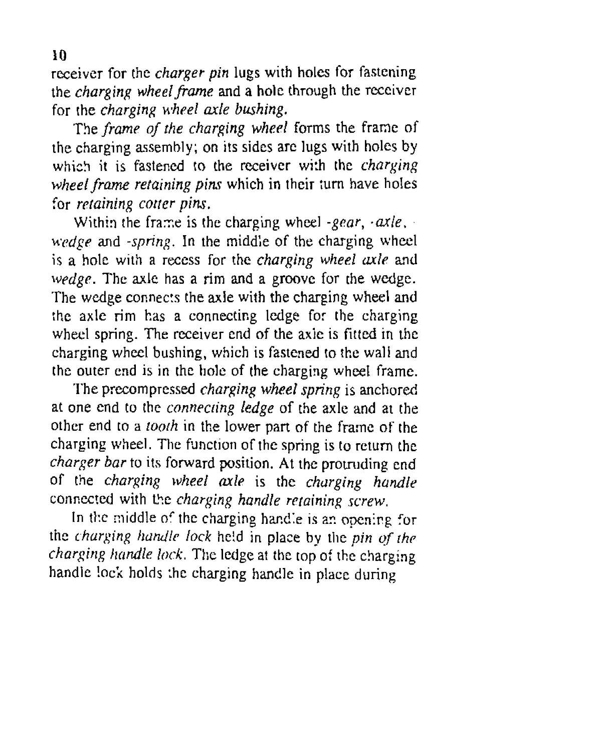
receiver for the charger- pin lugs with holes for fastening
the charging wheel frame, and a hole through the receiver
for the charging wheel axle bushing.
The frame of the charging wheel forms the frame of
the charging assembly; on its sides are lugs with holes by
which it is fastened to the receiver with the charging
wheel frame retaining pins which in their turn have holes
for retaining cotter pins.
Within the frame is the charging wheel -gear, -axle,
wedge and -spring. In the middle of the charging wheel
is a hole with a recess for the charging wheel axle and
wedge. The axle has a rim and a groove for the wedge.
The wedge connects the axle with the charging wheel and
the axle rim has a connecting ledge for the charging
wheel spring. The receiver end of the axle is fitted in the
charging wheel bushing, which is fastened to the wall and
the outer end is in the hole of the charging wheel frame.
The precompressed charging wheel spring is anchored
at one end to the connecting ledge of the axle and at the
other end to a tooth in the lower part of the frame of the
charging wheel. The function of the spring is to return the
charger bar to its forward position. At the protruding end
of the charging wheel axle is the charging handle
connected with the charging handle retaining screw.
In the middle or the charging handle is an opening for
the charging handle lock held in place by the pin of the
charging handle lock. The ledge at the top of the charging
handle lock holds the charging handle in place during
11
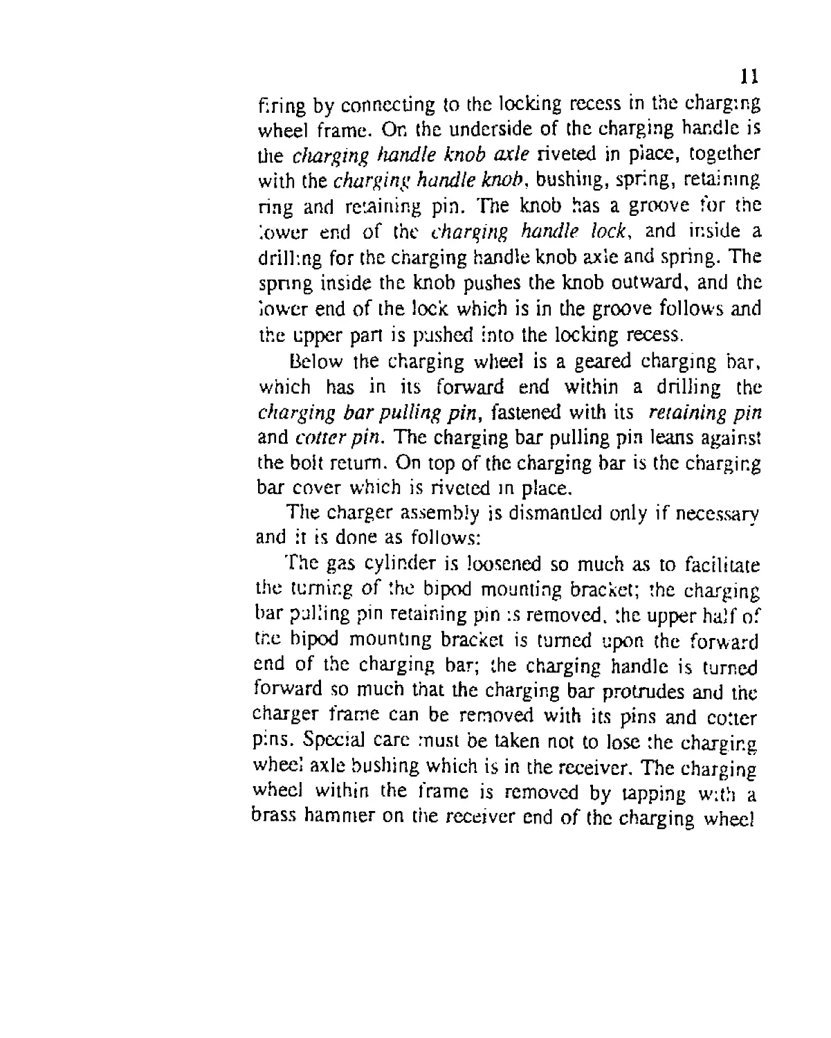
firing by connecting to the locking recess in the charging
wheel frame. On the underside of the charging handle is
die charging handle knob axle riveted in place, together
with the charging handle knob, bushing, spring, retaining
ring and retaining pin. The knob has a groove for the
lower end of the charging handle lock, and inside a
drilling for the charging handle knob axle and spring. The
spring inside the knob pushes the knob outward, and the
lower end of the lock which is in the groove follows and
the upper part is pushed into the locking recess.
Below the charging wheel is a geared charging bar,
which has in its forward end within a drilling the
charging bar pulling pin, fastened with its retaining pin
and cotter pin. The charging bar pulling pin leans against
the bolt return. On top of the charging bar is the charging
bar cover which is riveted in place.
The charger assembly is dismantled only if necessary
and it is done as follows:
The gas cylinder is loosened so much as to facilitate
the turning of the bipod mounting bracket; the charging
bar pulling pin retaining pin is removed, the upper half of
the bipod mounting bracket is turned upon the forward
end of the charging bar; the charging handle is turned
forward so much that the charging bar protrudes and the
charger frame can be removed with its pins and cotter
pins. Special care must be taken not to lose the charging
wheel axle bushing which is in the receiver. The charging
wheel within the frame is removed by tapping with a
brass hammer on the receiver end of the charging wheel
12
axle while the charging wheel feces down, and care must
be taken not to lose the charger wheel wedge. The
charging wheel spring is removed. The charging handle
knob is stripped by hitting on the charging handle knob
retaining ring retaining pin through the drilling in the
knob, thus removing the pin. (when assembling, the
retaining pin end must be riveted}.
Assembly is done in reverse order. The following
must be noted:
If the charging handle is removed it must be assembled
to the charging wheel axle so that the wedge faces up
juxtaposed to the charging handle, because otherwise it is
not possible to precompress the charging wheel spring;
the charging handle inner connecting ledge is pressed
against the spring connecting ledge at the rim of the axle,
the spring is wound into the frame so much that it is
possible to replace the charging wheel and the wedge
upon the spring (the straight side of the charging wheel
comes against the ^ring); the charging handle is turned
until the spring’s outer end connecting ledge is withdrawn
into the tooth of the frame. The charging wheel frame is
then fastened and care must be taken that the charging
wheel axle bushing is in its place in the receiver and that
the charging wheel retaining pin is locked with the cotter
pins. The spring is completely compressed by turning the
charging handle; the handle is reversed a quarter of a turn
and the charging bar and the charging wheel gears are
connected so that when the charging handle is in its
locked position the end of the charging bar is at the same
plane as the front of the receiver.
13
The charging bar pulling pin is replaced and secured
with its pin and cotter pin.
At the rear of the receiver is a drilling through both
walls for the connecting pin and on the right below the
drilling there is a recess for securing the connecting pin
to its closed position.
2. Bolt and bolt return assembly.
A hole is drilled through the bolt for the firing pin, the
hole is smaliet in its forward end; and at the border of the
bigger and smaller hole is a ledge which restricts the
forwaid movement of the firing pin. At the rear of the
hole, above and below are recesses with flat bottoms that
end at the connector space, above for the coddng- and
connector- support ledges of die firing pin and below for
the firing pin cocking ledge.
At the rear of the bolt are threads for attaching the
bolt cap and below a space for the firing pin retainer and
a vertical space through the bolt, the connector space.
Below the bolt is a lengthwise opening for the firing
pin cocking ledge which is on top of the bolt return
assembly, and for the connector opening ledge. In front
of the opening is a recess for the bolt retractor ledge
which restricts die bolt and bolt return assembly forward
and rearward movement compared to each other.
In front of the recess is a space for the extractor,
extractor spring and extractor spring guiding rods, and a
drilling for the extractor pin.
Above the boll are fracks that reach to the front of
14
the connector space, with a groove for the ejector ledge.
The tracks support the newt cartridge in line when the holt
moves rearward and when the bolt goes forward the ends
of the tracks push the cartridge into the chamber.
At the face of the bolt is a recess for the head of the
cartridge, onto which the extractor with the help of its
springs grips the exiting cartridge case.
At the left front of the bolt is a hole that reaches the
firing pin hole to facilitate gas bleeding in case of a
pierced primer.
Parts of the bolt: firing pin, which has a drilling for
the firing pin spring and two ledges above, die rear is the
firing pin cocking ledge and the front :s the connector
support ledge, which prevents the connector from pushing
down before the firing pin cocking ledge has reached
behind the firing pin retainer to its cocked position and
below the firing pin cocking retractor ledge. The front of
the firing pin is smaller and thus there is a ledge at the
border of die thicker and smaller part, which restricts the
firing pin movement within the bolt.
At the front end of the extractor is a ledge for pulling
the cartridge case and at its rear there is a support ledge,
which leans against a similar ledge in the bolt when the
extractor functions. In the middle is a hole for the
extractor pin and behind there are recesses far the heads
of the extractor spring guide rods.
On top rear of the connector is an angled locking
surface and in the middle an opening for the firing pin;
above and behind the opening is an angled surface into
which the firing pin connector support ledge is pressed
with the force of the firing pin spring when the bolt goes
15
forward holding the connector in its lower position as the
bolt return assembly forces the bolt to its forward
position. (The push is directed through the angled surface
of the lower part of the connector, thus the connector
tries to rise against the similar surface in the receiver).
Below and in front of the opening is an angled connector
lock, opening surface, into which the bolt return assembly
similar opening ledge hits, forcing the connector down.
The lower angle works as the connector locking surface.
On top of the firing pin retainer are drillings for the
firing pin retainer springs and in the middle there is an
opening for the firing pin. Above the opening at the rear
there is an angled cocking surface similar to the firing
pin’s and below an angled ledge which connects the bolt
return assembly relay during firing and behind it, with a
ledge below, which prevents placing the part wrong
during assembling.
The bolt cap closes the rear end of the bolt. Within
are threads for fixing it to the bolt. In the middle is a hole
for the riveted firing pin guide rod.
The firing pin spring together with the firing pin
facilitates the shot.
The boh return assembly cocks the firing pin with the
force of the push given by the gas cylinder, opens the
locked connector, retracts die bolt and compresses the
bolt return spring. When going forward it returns the bolt
and locks the connector.
Within the bolt return assembly is a drilling for the
spring, in front cm top is the holt return ledge, the firing
pin cocking retractor ledge and connected to the last the
angled connector opening ledge.
16
To the rear of the ledge is a recess for the lower part
of the connector, the angled side functions as the
connector locking lifter and the lengthwise recess as the
moving space of the firing pin retainer lower ledge and a
trough for the relay, which relays the trigger movement
to the firing pin retainer and a threaded hole for the relay
retainer screw. Below at the rear is the boll reiurn
assembly reiaining ledge and at the right in front is a
recess with a round floor for the charger bar pull pin.
3. Gas cylinder.
The function of the gas cylinder and the gas piston
within is to give the retracting movement to the bolt
assembly by the help of gas pressure flowing through the
gas hole in the barrel.
The pans of the gas cylinder are: The gas cylinder
which has a drilling for the gas piston. Above it are two
mounting rings that fit around the barrel; the ring in front
has the front sight attached on the left side by the front
sight rivets', below in front within its space is the gas
cylinder nut lock, spring, and retaining pin, 'ITirough the
upper wall of the ring is a hole drilled which reaches the
gas cylinder, connected to the gas hole in the barrel.
In the front end of the gas cylinder drilling are threads
for the gas cylinder plug, and at the forward end a
locking recess for the gas cylinder plug lock.
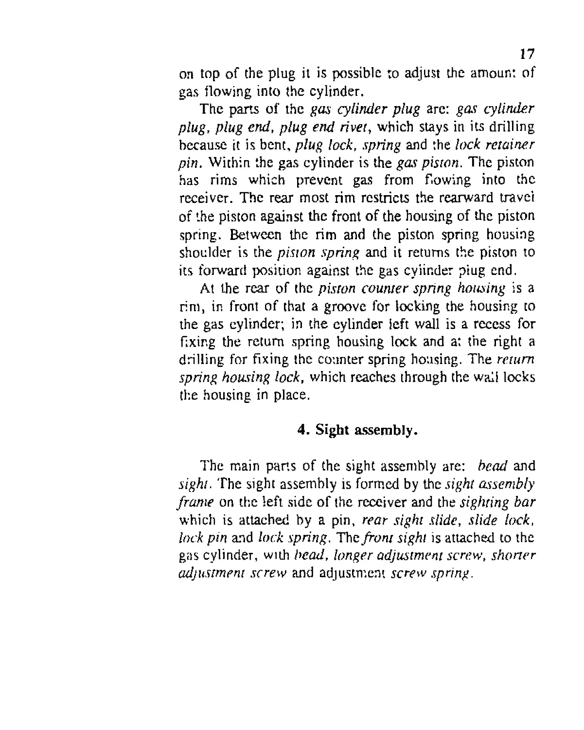
T~he gas cylinder plug closes the forward end of the
gas cylinder; with the differently sized adjustment holes
17
on top of the plug it is possible to adjust the amount of
gas flowing into the cylinder.
The parts of the gas cylinder plug are: gas cylinder
plug, plug end, plug end rivet, which stays in its drilling
because it is bent, plug lock, spring and the lock retainer
pin. Within the gas cylinder is the gas piston. The piston
has rims which prevent gas from flowing into the
receiver. The rear most rim restricts the rearward travel
of the piston against the front of the housing of the piston
spring. Between the rim and the piston spring housing
shoulder is the piston spring and it returns the piston to
its forward position against the gas cylinder piug end.
At the rear of the piston counter spring housing is a
rim, in front of that a groove for locking the housing to
the gas cylinder; in the cylinder left wall is a recess for
fixing the return spring housing lock and a: the right a
drilling for fixing the counter spring housing. The return
spring housing lock, which reaches through the wall locks
the housing in place.
4. Sight assembly.
The main parts of the sight assembly are: bead and
sight. The sight assembly is formed by the sight assembly
frame on the left side of the receiver and the sighting bar
which is attached by a pin, rear sight slide, slide lock,
lock pin and lock spring. The front sight is attached to the
gas cylinder, with bead, longer adjustment screw, shorter
adjustment screw and adjustment screw spring.
18
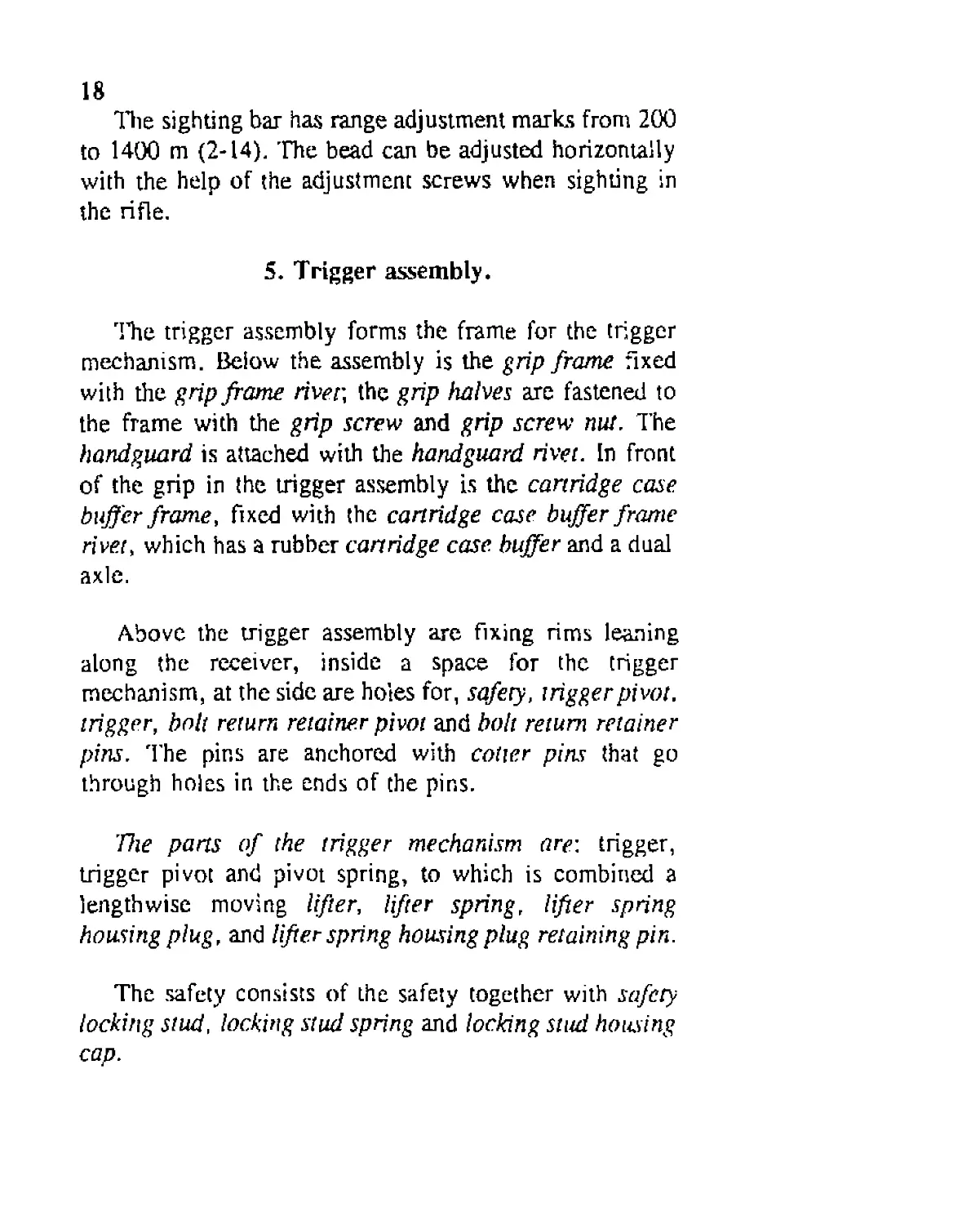
The sighting bar has range adjustment marks from 200
to 1400 m (2-14). The bead can be adjusted horizontally
with the help of the adjustment screws when sighting in
the rifle.
5- Trigger assembly.
TTie trigger assembly forms the frame for the trigger
mechanism. Below the assembly is the grip frame fixed
with the grip frame river, the grip halves are fastened to
the frame with the grip screw and grip screw nut. The
handguard is attached with the handguard rivet. In front
of the grip in the trigger assembly is the cartridge case
buffer frame, fixed with the cartridge case buffer frame
rivet, which has a rubber cartridge case, buffer and a dual
axle.
Above the trigger assembly are fixing rims leaning
along the receiver, inside a space for the trigger
mechanism, at the side are holes for, safety, trigger pivot,
trigger, bolt return retainer pivot and boh return retainer
pins. The pins are anchored with cotter pins that go
through holes in the ends of the pins.
The parts of the trigger mechanism are-, trigger,
trigger pivot and pivot spring, to which is combined a
lengthwise moving lifter, lifter spring, lifter spring
housing plug, and lifter spring housing plug retaining pin.
The safety consists of the safety together with safety
locking stud, locking stud spring and locking stud housing
cap.
19
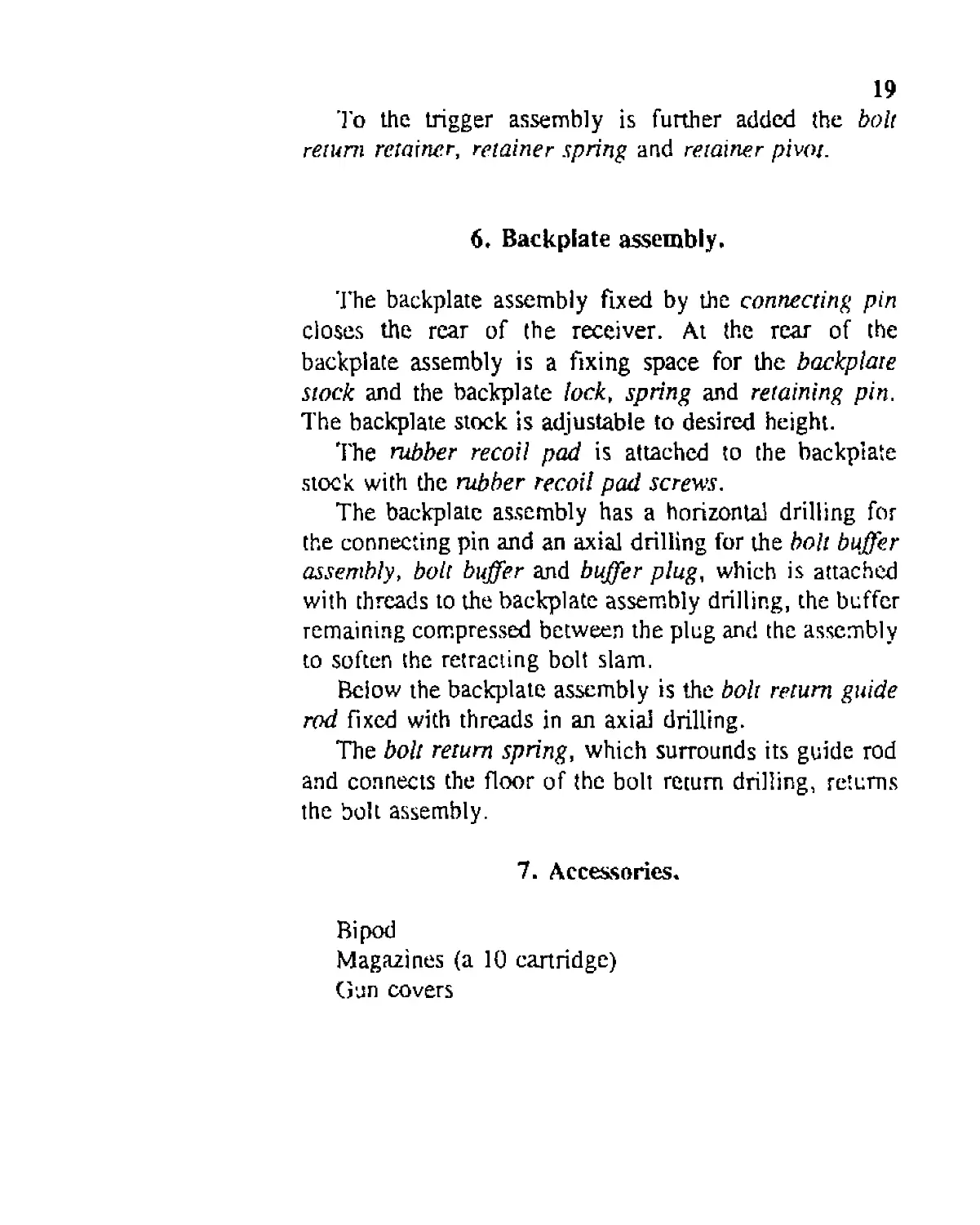
'I'o the trigger assembly is further added the bolt
return retainer, retainer spring and retainer pivot.
6. Backplate assembly.
The backplate assembly fixed by the connecting pin
closes the rear of the receiver. At the rear of the
backplate assembly is a fixing space for the backplate
stock and the backplate lock, spring and retaining pin.
The backplate stock is adjustable to desired height.
The rubber recoil pad is attached to the backplate
stock with the rubber recoil pad screws.
The backplate assembly has a horizontal drilling for
the connecting pin and an axial drilling for the bolt buffer
assembly, bolt buffer and buffer plug, which is attached
with threads to the backplate assembly drilling, the buffer
remaining compressed between the plug and the assembly
to soften the retracting bolt slam.
Beiow the backplate assembly is the boh return guide
rod fixed with threads in an axial drilling.
The bolt return spring, which surrounds its guide rod
and connects the floor of the bolt return drilling, returns
the bolt assembly.
7. Accessories.
Bipod
Magazines (a 10 cartridge)
Gun covers
20
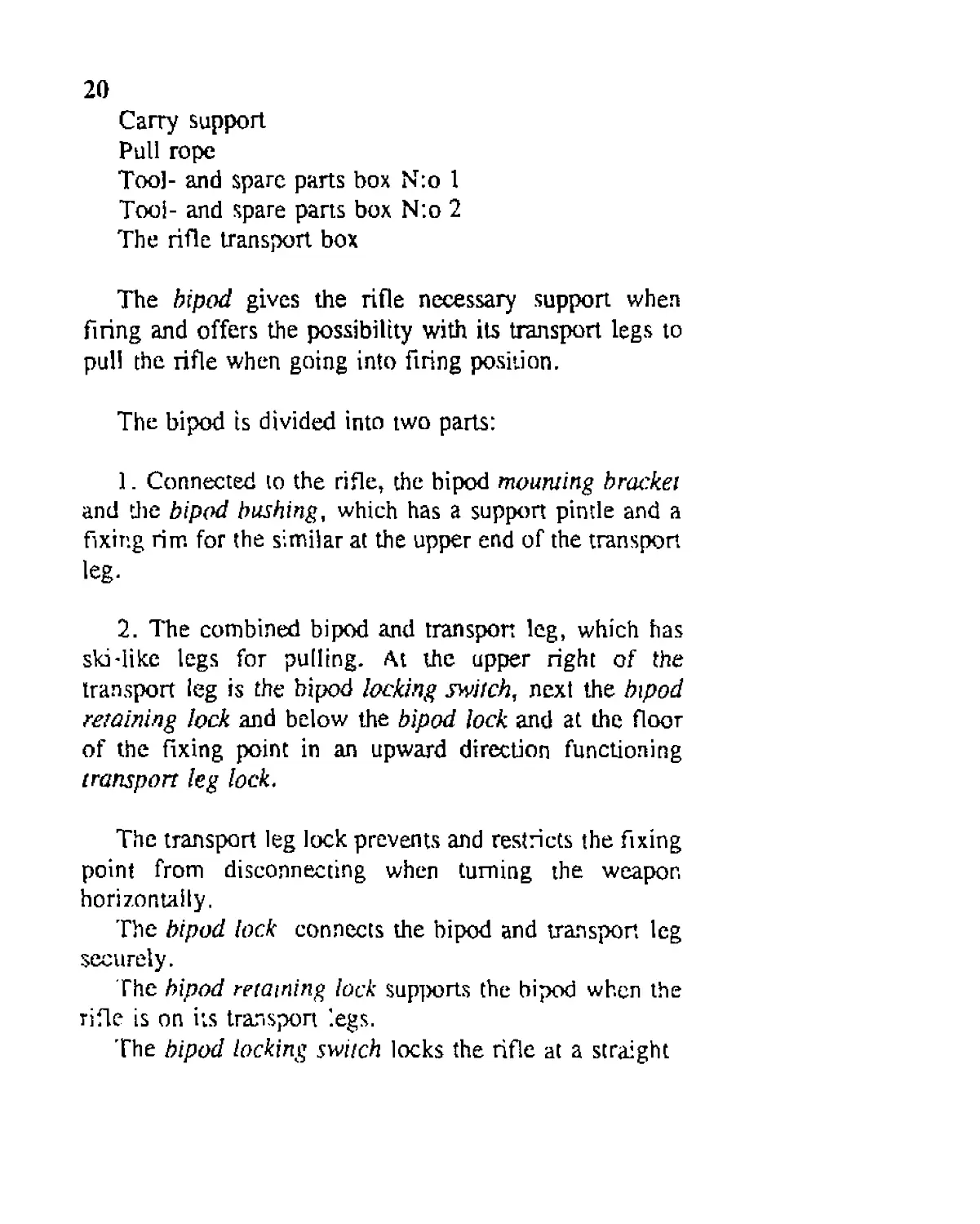
Cany support
Pull rope
Too]- and spare parts box N:o 1
Tool- and spare parts box N:o 2
The rifle transport box
The bipod gives the rifle necessary support when
firing and offers the possibility with its transport legs to
pull the rifle when going into firing position.
The bipod is divided into two parts:
1. Connected to the rifle, the bipod mourning bracket
and die bipod bushing, which has a support pintle and a
fixing rim for the similar at the upper end of the transport
leg-
2. The combined bipod and transport leg, which has
ski-like legs for pulling. At the upper right of the
transport leg is the bipod locking switch, next the bipod
retaining lock and below the bipod lock and at the floor
of the fixing point in an upward direction functioning
transport leg lock.
The transport leg lock prevents and restricts the fixing
point from disconnecting when turning the weapon
horizontally.
The bipod lock connects the bipod and transport leg
securely.
The bipod retaining lock supports the bipod when the
rifle is on its transport legs.
The bipod locking switch locks the rifle at a straight
21
angle juxtaposed to the legs. At the inner side of the
transport leg are rings for attaching the pull rope.
The magazine feeds the cartridges in front of the bolt
face and after the last cartridge it releases the bolt
retainer from its lock with the help of the magazine
follower boll retainer depresser.
The magazine divides into the magazine body which
has three openings in the right wall, showing the amount
of cartridges, magazine follower and magazine floorplate
(Spare parts box N:o 2 contains the magazine filler tool).
Gun covers.
'ITie handguard facilitates carrying the rifle when the
barrel is hot. The wood guard is on the barrel between
the gas cylinder and the muzzlebrake.
The cloth cover is meant to protect the rifle during
transport and between use.
The carry support eases carrying the rifle over the
shoulder. It is fastened below the rifle with two screws at
the chin support.
The muzzlebrake cover closes the front end of the
barrel. It is fastened by a chain to the neck of the
muzzlebrake so that it does not get lost. The muzzlebrake
cover must be removed before firing!
The pull rope is used to pull the rifle into the firing
position. It is attached to the rifle so that the spring
locked hooks are attached to the rings on the bipods and
the barrel guide comes above the barrel with the rope
remaining below it.
22
Tool- and spare parts box N:o / contains the listed
tools and spare parts for fieldwork.
Tool- and spare parts box N:o 2 contains the listed
tools and spare parts.
The rifle transport box contains the rifle and the listed
accessories.
III. DISASSEMBLING THE RIFLE
1. General.
The rifle is disassembled for cleaning, oiling, and for
inspection and parts maintenance. The unnecessary dis-
assembly of fighting rifles must be avoided and a certain
rifle should be reserved for training purposes due to the
fact that rifles used in training often malfunction.
When disassembling and assembling the rifle the
following must be noticed:
a) Disassembly and assembly must be performed in
such a place that does not expose the parts to dirt,
b) when removing or replacing rifle parts they must be
handled carefully, without abuse and unnecessary hitting.
Using the parts as hammers is absolutely forbidden,
hitting must be done with tools from the toolbox,
23
c) when assembling parts with threads, special care
must be taken that the threads start on track freely turned
by hand, and tools should be used only for the final
tightening,
d) the moving parts should be in their forward position
when beginning disassembly. For disassembly the rifle is
placed on its skis supported by its stock on a table or on
the ground, with the cover cloth underneath to prevent
parts from getting dirty.
2. Removing the muzzlebrake.
a) The cartridge case remover handle, which is in the
toolbox, is placed through the gas openings in the side of
the muzzlebrake, to prevent it from turning when opening
the muzziebrake locking nut,
b) with the tool from the toolbox the muzzlebrake
locking nut is turned clockwise open,
c) turning by hand the muzzlebrake and its nut are
removed,
d) the handguard is removed.
3. Removing the gas cylinder.
a) The gas cylinder locking nut is removed,
b) the gas cylinder is pulled off with care taken not to
dent the treads on the barrel.
24
4. Disassembling the gas cylinder.
a) At the rear of the gas cylinder, the gas piston return
spring housing locking spring is removed so that the end
going through the right side is carefully pried out of its
hole with care taken not to bend the spring too much,
b) the gas piston return spring housing, spring and gas
piston are removed from the rear,
c) the gas cylinder plug in front is removed by
depressing the lock and turning the plug counter-
clockwise; the end of the plug shall be removed only in
the case that the gas pressure must be adjusted in the
cylinder, which is done by removing the plug end rivet
and the desired sized hole is turned facing the marking
arrow.
5. Removing the backplate assembly.
a) With the flat of the left hand the backplate assembly
is pushed forward and with the right hand the connector
pin lever is turned 90 degrees up and pulled out. When
the pin is removed the bolt return spring pushes the
backplate assembly outward, and must thus be supported
with force,
b) the backplate assembly and the bolt return spring
are removed.
6. Removing the grip and trigger assembly.
The grip and trigger assembly is pulled to the rear in
the tracks in the receiver so much as to remove them
from the receiver.
25
7. Removing the floor of the receiver.
The floor of the receiver is removed by pulling it
rearward until it detaches.
8. Removing the bolt and bolt return assembly.
By turning the cocking handle the bolt and bolt return
assembly is retracted so far that the locking connection
between the bolt and barrel is opened, then the bolt return
is pulled from the locking ledge under it until it is
removed from the receiver, and the bolt follows.
9. Stripping the bolt.
a) The bolt face is pressed against a soft support; the
flat of the right hand removes the bolt cap by turning
counterclockwise; when the cap is released from its
threads care must be taken that the firing pin spring does
not push the cap away rapidly, which could lead to a bent
spring,
b) the firing pin is removed by pushing the firing pin
retainer up and pulling the firing pin from its cocking
ledge out to the rear from under the bolt,
c) the connector is removed,
d) the firing pin retainer with spring and guide is
removed,
e) the extractor with spring and guide is removed by
hitting the extractor pin out of its drilling with a driving
pin.
26
The disassembly of the extractor is not recommended
at the same time with the firing pin retainer, because it is
possible to accidently mix the springs, as their length
difference is small.
10. Stripping the bolt return assembly.
a) The relay retaining screw is removed with a
screwdriver,
b) the relay is removed, which is however not
necessary during every cleaning.
11. Removing the bipod.
a) The bipod locking switch is pulled out and turned
to its most outward notches, facilitating the gun to turn
sideways in both directions.
b) the transport leg lock is depressed and at the same
time the gun’s rear is turned 90 degrees to the left,
removing the gun from the bipod by lifting from the
fixing point.
'fhe parts not mentioned above are disassembled only
when necessary.
IV. ASSEMBLING THE RIFLE
1. Fixing the rifle to its bipod.
The rifle is fixed to the bipod in the reverse order as
removing. It must be observed, that the bipod comes the
27
right way, switches to the right side of the nfle when
looking from the rear.
2. Assembling the bolt return assembly.
a) The relay is placed in its space so that the dual
forked end remains below the bolt return and the retaining
recess on the side of the retaining screw drilling,
b) the retaining screw is tightened with a screwdriver.
3. Assembling the bolt.
a) The extractor is placed so that its springs are in
their housing with the guides up; the extractor is
forcefully pushed with the left hand thumb into its space
and with the right hand pushing the pin into its drilling,
b) the firing pin, connector and firing pin retainer are
replaced so that the bottom of the bolt faces up, the
connector is fitted into its space so that the angled ledges
are aligned; the firing pin retainer springs are placed in
the drillings of the firing pin retainer with spring heads
first so that the guides face the floor of the housing in the
bolt; the bolt is turned on its side, the firing pin retainer
is replaced in its housing, the bolt is then turned bottom
facing up and the thumb forcefully presses the retainer
down and at the same time the firing pin is replaced
within its drilling. The firing pin cannot be replaced if it
is not in the right position; the cocking ledge in the
28
middle of the firing pin must be beiow the bolt when
pushing it into its place,
c) the firing pin spring and bolt cap are fastened so
that the spring is inserted into the drilling in the firing
pin, the spring guide which is at the end of the bolt cap
is pushed inside the spring, the boh head is supported
against some soft object, the bolt cap is pushed carefully,
without disrupting the spring, into its threads and turned
with the flat of the hand, until the cap is secured in the
threads, and then it can be freely turned shut.
4. Replacing the bolt and bolt return assembly
in the receiver
a) The bolt and bolt return assembly arc placed on top
of each other, so that the firing pin cocking ledge, which
is in the middle of the bolt return, comes in front of the
cocking ledge in the firing pin, and the bolt and bolt
return can press against each other.
b) The front end of the bolt return is supported against
a suitable object and holding the bolt return and bolt
together with the right hand, the boh is pressed into its
forward position, thus the firing pin is cocked and the
connector is pressed to the top level of the bolt,
c) the bolt and bolt return are pushed into the receiver
with the bolt return below, and it must be noted that the
bolt cap is turned in such position that the sides are
aligned with the bolt when it is pushed, so that the
receiver rear rims are not disrupted,
29
5. The receiver floor is replaced.
The receiver floor is pushed in place, and it must be
noted that the floor is pushed in place so that the end
which has angled track rims is forward, because if it is
reversed the backplate assembly cannot be fitted together
with the trigger assembly.
6. Replacing the grip and trigger assembly
The trigger assembly is pushed in place. It must be
noted that the safety on the left side of the trigger
assembly is turned rearward and is inserted following its
track to its place, between the cheek pad and the rim of
the receiver.
7. Assembling the backplate assembly
and the return spring.
a) The end of the bolt return spring is inserted into the
drilling in the bolt return assembly,
b) the spring guide of the backplate assembly is
inserted within the spring and the backplate assembly is
pushed into place,
c) the connecting pin is pushed to the bottom of its
drilling keeping the lever upright, the lever is turned 90
degrees to its locking position, observing that the
retaining ledge of the pin is aligned with the similar ledge
in the receiver when the lever is turned, not to wreck the
receiver!
30
8. Assembling the gas cylinder.
a) The gas cylinder plug is turned in place as much as
it goes. It must be noted that near the last turns the
retainer lock must be pressed each time the lock notch is
aligned, otherwise the lock attaches to the lock notch.
When the plug is turned as far as it goes it must be turned
back so much as to secure the lock in its notch, and it
must be observed that the plug is in right depth which can
be checked with the line which marks the gas opening that
is aligned with the tube rim,
b) the gas piston is pushed into the cylinder from the
rear with the piston head first.
c) the gas piston counter spring housing with spring is
pushed into place (it must be observed that the spring is
not forgotten!)
d) the gas piston return spring housing lock spring
which is at the rear of the gas cylinder is replaced so that
the longer end of the spring, which goes through the wall
of the cylinder, locks the gas piston housing in place.
9. Replacing the gas cylinder.
a) The gas cylinder is replaced from the front of the
barrel so that the rear of the cylinder goes through the
drilling of the front end of the receiver, and the forward
mounting ring is aligned with the ledge at the gas vent in
31
the barrel (when replacing the cylinder care must be taken
not to hit the threads in the barrel),
b) the gas cylinder locknut is turned into place,
c) the handguard is replaced.
10. Assembling the muzzlebrake and
muzzlebrake locknut.
a) The locknut is turned as far as it goes,
b) the muzzlebrake is turned as far as it goes and then
back so much that the gas openings at the sides point
level with the horizontal,
c) the handle of the cartridge case extractor is placed
through the side openings preventing the muzzlebrakc
from turning at the same time when the locknut is tightly
turned.
V. PREPARING THE RIFLE FOR FIRING,
IOADING, APPLYING THE SAFETY, AND
FUNCTION OF PARTS WHEN FIRING.
1. Cleaning and oiling before firing.
a) The rifle is carefully cleaned of grease (observe the
firing pin drilling in the bolt!) and inspected, that the
parts are in order, that the gas cylinder is assembled
correctly and the plug turned to the depth of the marking
line and locked,
32
b) the connector and firing pin is oiled, and care must
be taken that oil does not run to parts other than the
connector and the firing pin,
c) the bolt return assembly is oiled above at the rear
where the connector opening surfaces are and also the
relay,
d) within the receiver the connector floor is oiled and
from the space between the floor and rear of the receiver
which connects to the upper surface of the bolt,
e) in temperatures below -20 0 C it must be observed
not to place oil in other than b and c mentioned places.
(The gun works without greasing, thus it is safer nor to
grease the gun in temperatures lower than -30 ° C).
2. Loading the Rifle
a) The magazine catch is pushed forward with the flat
of the hand, causing the cover of the receiver to fling
open with the force of its spring,
b) the right hand grips the charging lever knob,
pushing it to the receiver wall, opening the charging lever
lock,
c) the charging lever is turned until the bolt and bolt
return assembly stays in the rear position held by the
retainer,
d) the charging lever is turned back to its forward
position (if this is not done the lever could hit the hand,
because when the bolt and bolt return goes forward the
33
cocking lever is spinned at a high speed to its forward
position, which could also lead to the malfunction of the
charger assembly),
e) the magazine is attached, with care taken that the
magazine catch closes,
f) when the rifle is against the gunner’s shoulder
supported on the bipod,(no/ the skis, because they are
only for transport), the gunner grasps the grip with his
right hand, pressing with the three lower fingers on the
bolt retaining lever, thus releasing the bolt and bolt return
to go forward and the bolt pushes a cartridge into the
chamber.
3. Applying the safety.
The rifle is put on safe by turning the safety lever on
the left side of the receiver to the rear to its retaining
notch marked by an arrow.
4. Function when firing.
a) When the gunner has removed the safety by turning
the safety lever to its forward position and with his right
hand taken hold of the grip so, that the three lowest
fingers press the bolt return retainer lever, (the lever must
be pressed continuously if it is desired to fire by pulling
the trigger only, because if the lever is released during
firing the bolt remains in its rear position, and the
unnecessary releasing of the bolt must be performed) and
places his pointing finger on the trigger and pulling it,
Note; It is imperative that the gunner place his left band in a position
rearward of the handguard io prevent his hand from being hit by an
ejecting cartridge case!
34
then the ledge at the upper front of the trigger presses the
rear of the trigger lever and forces the front end,
combined with the lengthwise moving lifter, to rise,
which in its turn transfers the movement with the help of
the relay to the firing pin retainer and frees the firing pin,
which rushes forward with the force of its spring, firing
the cartridge.
b) When the bullet has passed the gas opening in the
middle of the barrel, gas can flow into the gas cylinder.
Gas pushes the gas piston to the rear and the rear of the
piston transfers the movement to the bolt return, escorting
it for some 40 mm and returns with the force of its return
spring to its forward position. The bolt return continues
rearward with the bolt remaining in the locked position,
until the firing pin cocking ledge, which is on top of the
bolt return, has cocked the firing pin, after which the
connector opening ledge at the rear top collides with the
similar ledge in the connector, the angled opening
surface, forcing the connector down, after which the bolt
return ledge, which is on top of the bolt return, pulls the
bolt with its own rearward movement, bringing with the
help of the extractor the cartridge case out of the chamber
and compressing the bolt return spring. When the face of
the bolt reaches the ejector, the upper rim of the cartridge
case collides with the ejector and as the extractor resists
from below, the case is ejected out from under,
c) when the bolt and bolt return have reached their
rearward position and the next cartridge within the
15
magazine has lowered in front of the bolt face, then the
compressed return spring pushes the bolt and bolt return
forward and the bolt places the cartridge in the chamber,
d) when the movement of the bolt stops against the
rear of the barrel and the gunner still pulls the trigger, the
bolt return continues still forward and forces the
connector to rise with the help of the angled surface in
the bolt return, forming a secure lockup between barrel,
bolt and receiver,
e) because the gunner still holds the trigger in its rear
position the lifter in the front end of the trigger lever has
been above the relay forks in the bolt return, thus they
push with the forward movement of the bolt return, after
the connector has closed, the lifter in front of them,
which moves within its space compressing its return
spring. The lifter in the trigger lever facilitates
semiautomatic fire,
f) when the gunner releases the trigger, the trigger
lever spring lifts the trigger end of the lever up, while the
front goes down with its lifter, retracting with the help of
its spring to the start position in line with the relay at the
rear end of the bolt return, for a new shot,
g) when the gunner pulls the trigger again, a shot
occurs and the cycle continues as described above, until
the cartridges end or the gunner releases his grip on the
bolt return lever. After the last cartridge is fired the bolt
remains to the rear held by the bolt retainer in the
36
magazine catch frame, the bolt retainer depressor in the
magazine follower frees the bolt retainer from its lock,
and then the bolt retainer is pushed by the force of its
spring down in front of the bolt face,
h) when the gunner presses strongly against the
magazine catch, a lever, which is part of the magazine
catch, lifts the bolt retainer letting the bolt and bolt return
slightly forward to stay against the bolt return retainer:
the empty magazine is removed by pushing continuously
on the magazine catch. If the magazine catch is not
pushed enough it leads to the situation that the bolt is still
arrested by the bolt retainer and the bolt and the bolt
return cannot be let forward by pulling on the bolt return
lever. This malfunction is removed by pushing the
magazine catch again with the flat of the hand, as far as
it goes,
i) a full magazine is replaced and the rifle is ready to
fire, when the gunner pulls the bolt return retainer lever,
as described above, it lets the bolt and bolt return travel
to their forward position, and a new cartridge is inserted
in the barrel.
VI. MAINTENANCE DURING FIRING AND
CLEANING AFTER FIRING
1. Maintenance during firing.
a) When firing many consecutive rounds with the rifle
the bolt and bolt return must be removed from the rifle
37
at first chance and the receiver must be cleaned of the dirt
accumulated by the powder gases, which otherwise will
dry to a sticky residue on the bolt and bolt return gliding
surfaces, making their movement more difficult especially
during winter.
b) dried dirt is easily removed by wiping with a rag
moistened with benzine (gasoline), after which the
benzine must be carefully dried off and the parts oiled, as
has been earlier described when preparing the rifle for
firing,
c) the chamber must be brushed with the chamber
brush, which is in the toolbox, through the magazine
opening. It must be observed that the brush is clean and
free from sand and it must not be too greasy.
d) If the magazine is not fastened, then the receiver
cover must be closed and the bolt and the bolt return must
be let to their forward position. Letting the boll freely
forward, must be avoided, because it hits the rear of the
barrel unnecessarily and stresses the pans, so this has to
be done by turning the charging lever to the rear and
letting the parts slowly forward by holding on to the
lever.
2. Cleaning the rifle after Firing.
a) The rifle is disassembled, as has been described
previously and using the cleaning equipment from the
toolbox the parts are thoroughly cleaned, greased evenly
with a thin layer of oil and the barrel with storing grease
(special care must be taken in cleaning rhe barrel,
chamber, gas cylinder, and the firing pin drilling within
the boh).
38
VII. MALFUNCTIONS
Case 1.
The moving parts do not go forward when pulling the
retainer lever, the lever feels to move lightly and the
trigger feels light.
Reason for the malfunction.
The magazine catch has not been pushed forward
enough when changing the magazine, which means that
the bolt retainer has not risen enough to stay in its lock,
and is still in front of the boh face, preventing the bolt
return assembly from reaching its retainer, or the bolt
retainer has for some reason, in the middle of firing
loosened from its lock and is pressed in front of the bolt
face.
Removing the malfunction.
With the flat of the hand the magazine catch is pushed
strongly forward, when a snap is audible and the bolt is
released from its retainer and moves slightly forward to
stay by the bolt return retainer. By pulling on the retainer
iever the moving parts are let forward and firing can
continue.
Case 2.
7fa? trigger feels light and a shot cannot be made.
39
Reason for the malfunction.
The moving pans are not completely forward; the
relay in the bolt return assembly is not aligned with the
trigger lever lifter.
The malfunction can be caused by a dirty or damaged
cartridge or for some reason slowed forward movement
of the bolt, and thus the bolt return has not had the
energy to go completely to the forward position.
Removing the malfunction.
The charging lever is turned a quarter of a turn and it
is quickly released. If the trigger still feels light, the
above is redone. If this does not help, the cartridge is
removed from the chamber by reloading and a new
cartridge is inserted. If the malfunction still occurs, the
magazine is removed and also the cartridge in the
chamber. The broken or tired bolt return spring is
replaced with a new one and the dirty rifle is cleaned.
Case 3.
The trigger feels light, no shot can be made and
turning the charging lever a quarter of a turn the charger
bar pulling piece does not seem to retract the bolt return
assembly.
Reason for the malfunction.
Faulty feed from the magazine; the rear of the
cartridge is delayed and the bolt has passed over the
cartridge rim and the canridge has been wedged between
the bolt head and the receiver, leaving the bolt half open.
40
The malfunction can also be caused by the magazine
catch not being completely closed, and the throat of the
magazine not being low enough, making the bolt push the
cartridge from the middle.
Removing the malfunction.
A complete charging mation is done, the magazine is
removed and also the cartridge which caused the
malfunction.
Case 4.
A cartridge not firing.
Reason for the malfunction.
There is grease or dirt in the bolt’s drilling for the
firing pin and it hits weakly; the firing pin point has
broken', the firing pin spring is tired or broken-, the bolt
return is not completely forward and the firing pin hits
the firing pin cocking ledge in the bolt return assembly,
this could happen from a tired or broken bolt return
spring or winter cold and dirt making the bolt and bolt
return go slowly forward.
Removing the malfunction.
The charging lever is turned a quarter of a turn,
cocking the firing pin again. The charging lever is
quickly released and a new shot is attempted. If the
cartridge still does not fire, it is removed by completely
reloading and a new cartridge is inserted in the chamber.
If the cartridge still does not fire, the magazine is
removed and also the cartridge. The reason for the
malfunction is inspected according to the list above, and
41
is removed. If din is the reason, then the rifle is cleaned.
Case 5.
The cartridge case is left between the boh head and
the floor or the cartridge is between the boh head and the
receiver.
Reason for the malfunction.
There is not sufficient gas pressure within the gas
cylinder; the extractor is broken; or the rifle is too
greased in winter cold; or it has dried powder gas residue
on the gliding surfaces.
Removing the malfunction.
If the cartridge case does not have a dent left by the
ejector, then the retracting movement of the bolt is too
slow. The gas cylinder plug is unscrewed and the next
bigger gas hole is placed in line with the marking arrow.
A broken extractor is replaced with a new one and the
rifle is cleaned, if dirt and grease are the cause of the
malfunction.
When the malfunction described occurs, the magazine
must absolutely be removed and a complete reloading
must be made and the chamber must be inspected to be
empty. If there is a cartridge in the chamber, the bolt and
bolt return is let forward and the magazine is replaced,
and then the rifle is ready to fire.
42
Case 6.
The rims of the cartridge cases break.
Reason for the malfunction.
The bolt retracts with too great a speed.
Removing the malfunction.
The gas cylinder plug is removed and the next smaller
gas hole in the end of the plug is aligned with the
marking arrow.
Case 7.
The cartridge case does not fit in the chamber.
Reason for the malfunction.
A broken cartridge case.
Removing the malfunction.
The broken cartridge case is removed with the
cartridge case removing tool.
Obs.! It is an advantage for the functioning of the
rifle if the cartridges used are lightly oiled before filling
the magazine.
43
VIU. TOOL- AND SPARE PARTS LIST
Tool- and spare parts box N:o 1
Amt.
1
1
1
2
2
1
1
2
2
1
1
1
1
1
1
1
1
1
1
1
1
Spare parts.
Part N:o Part name
18 77 78 80 81 83 84 86 87 Sight bar pin Extractor Extractor pin Extractor spring Extractor spring guide rod Firing pin Firing pin spring Firing pin retainer spring Firing pin retainer spring guide rod Tools.
261 265 266 272 273 274 275 276 277 278 279 289 Universal tool* Hook-wrench • Cartridge case remover* Driving pin 1,9 mm Driving pin 2,8 mm Driving pin 3,8 mm Driving pin 5,5 mm Driving pin 8,0 mm Driving pin 10,0 mm Firing pin hole cleaner Cleaning rod • Chamber brush
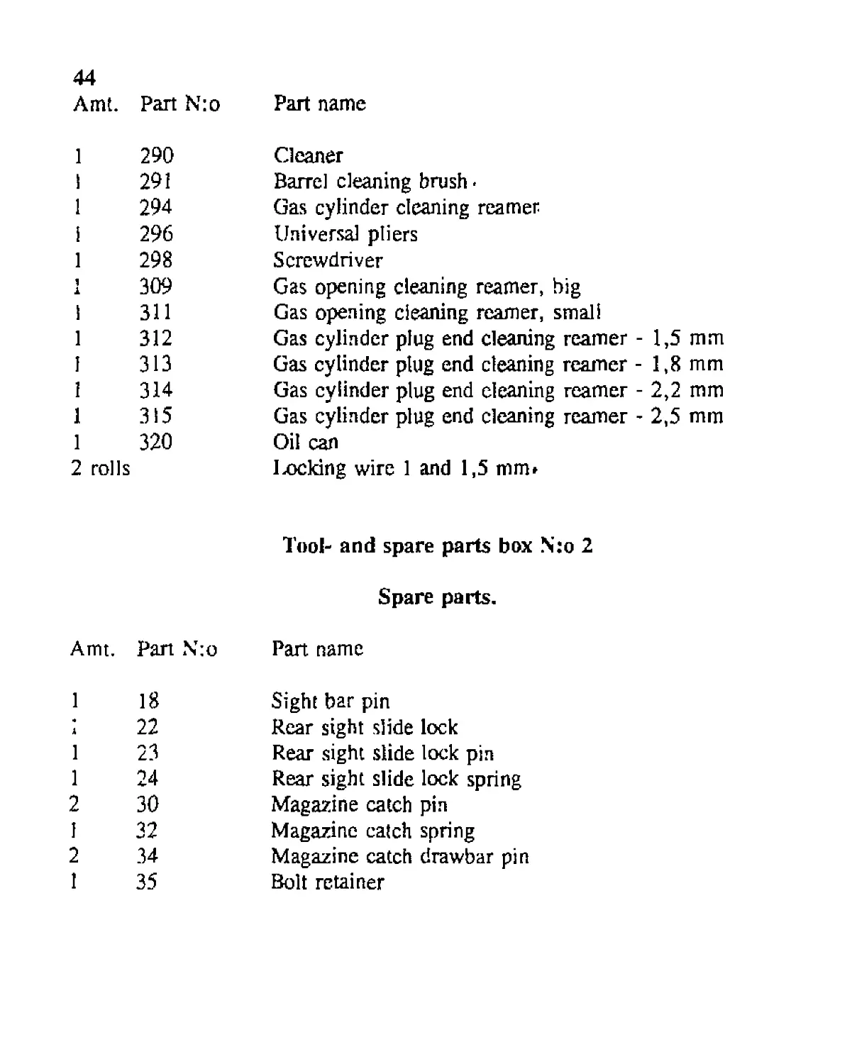
44 Amt. Part N:o Part name
1 290 i 291 1 294 i 296 1 298 1 309 i 311 1 312 1 313 1 314 1 315 1 320 2 rolls Cleaner Barrel cleaning brush - Gas cylinder cleaning reamer Universal pliers Screwdriver Gas opening cleaning reamer, big Gas opening cleaning reamer, small Gas cylinder plug end cleaning reamer - 1,5 mm Gas cylinder plug end cleaning reamer - 1,8 mm Gas cylinder plug end cleaning reamer - 2,2 mm Gas cylinder plug end cleaning reamer - 2,5 mm Oil can lacking wire 1 and 1,5 mm» Tool- and spare parts box N:o 2 Spare parts.
Amt. Part N:o Part name
1 18 1 22 1 23 1 24 2 30 1 32 2 34 1 35 Sight bar pin Rear sight slide lock Rear sight slide lock pin Rear sight slide lock spring Magazine catch pin Magazine catch spring Magazine catch drawbar pin Bolt retainer
45
Amt. Part N:o Part name
4 36 Boh retainer spring
4 37 Bolt retainer spring guide rod
1 38 Bolt retainer lock
2 39 Bolt retainer lock spring
1 53 Charging wheel
1 53a Charging wheel spring
1 54 Charging wheel pin
2 57 Charging wheel housing retaining pin
2 59 Charging wheel wedge
1 61 Charging lever retaining screw
1 63 Charging lever lock pin
2 72 Charger bar pull pin
1 73 Charger bar pull pin retaining pin
1 77 Extractor
i 78 Extractor pin
9 80 Extractor spring
2 81 Extractor spring guide rod
1 82 Connector
I 84 Firing pin spring
i 85 Firing pin retainer
2 86 Firing pin retainer spring
2 87 Firing pin retainer spring guide rod
1 92 Relay
1 93 Relay retaining screw
I 106a Gas cylinder plug head
1 106b Gas cylinder plug rivet
1 111 Piston head (removed in the newer rifles)
9 a* 112 Piston head rivet
46
Amt, Part N:o Pan name
2 113 1 120- 1 121- 1 122- 1 123- I 130b 2 132 2 133 2 134 1 136 2 138 2 141 I 144 2 147 2 153 2 154 1 155- 1 156- 1 157- 1 158- 1 162 I 164 1 165 1 166 1 167 2 182 Piston counter spring Safety (Part N:o F is complete assembly, #120-123) Safety locking stud Safety locking stud spring Safety locking stud housing cap Cartridge case buffer Lifter spring Lifter spring housing plug Lifter spring housing plug retaining pin Trigger lever pin Trigger lever spring Trigger pin Bolt return retainer lever pin Bolt return pin Grip screw Grip screw nut Connecting pin (Part N :o H is complete assembly ,# 155-158) Connecting pin locking stud Connecting pin locking stud spring Connecting pin locking stud housing cap Bolt buffer Rear plate lock Rear plate lock spring Rear plate lock retaining pin Bolt return spring Bipod bushing axle
47
Amt. Part N:o Part name
2 183 Bipod bushing axle nut
2 185 Bipod bushing counter spring
2 187 Bipod bushing counter spring pushrod
2 188 Bipod bushing counter spring pushrod pin
I 199 Transport leg lock
I 200 Transport leg lock spring
2 202 Transport leg lock lever retaining screw
1 204 Bipod lock
1 205 Bipod lock spring
i 208 Bipod locking switch lock
1 209 Bipod locking switch spring
I 211 Bipod locking switch retaining pin
1 213 Bipod retaining lock
1 214 Bipod retaining lock spring
Tools.
1 297 Round jaw pliers
1 299 Oil can, bigger
1 304 Rubber hammer
1 305 Magazine filler-
9 4» rolls Locking wire 1 and 1,5 mm
20 at. rif. /39
list of transport box contents
1 Rifle, complete-
1 Bipod, complete-
48
1 1 1 1 1 4 8 1 1 1 1 Muzzlebrake* Rear plate assembly Handguardfof barrel) Tool- and spare parts box N:o 1 Tool- and spare parts box N:o 2 Magazine cases- Magazines(in the 4 cases) • Gun cover Rear carry support Pull rope Muzzlebrake cover/ Barrel cleaning wads Rags(cloth)
Further there is room in the transport box for the front and rear supports that
belong to the transport vehicle.
IX. LIST OF RIFLE PARTS
Part N:o Part description
A. B. 1 2 3 4 9 10 Rifle, complete Receiver, assembled (parts 1-75) Receiver Barrei Muzzlebrake Muzzlebrake locking nut Banel retaining screw Magazine pin
Part N:o
11
12
13
14
15
16
17
18
19
20
21
22
23
24
25
26
27
28
29
30
31
32
33
34
35
36
37
38
49
Part description
Magazine pin support ring
Magazine pin cotter pin
Receiver cover
Recover cover spring
Sight assembly frame
Sight assembly frame rivet
Sighting bar
Sighting bar pin
Sighting bar spring
Rear sight slide, assembled(parts 21-24)
Rear sight slide
Rear sight slide lock
Rear sight slide lock pin
Rear sight slide lock spring
Magazine catch frame
Magazine catch frame rivet
Magazine catch frame rivet
Magazine catch frame rivet
Magazine catch
Magazine catch pin
Magazine catch pin cotter pin
Magazine catch spring
Magazine catch pawl
Magazine catch pawl pin
Bolt retainer
Bolt retainer spring
Boit retainer spring guide rod
Bolt retainer lock
50 Part N:o Part description
39 40 41 42 43 44 53 53a 54 55 56 57 58 59 60 61 62 63 64 65 66 67 68 69 70 70a 71 71a Bolt retainer lock pin Bolt retainer lock spring Bolt retainer housing cap Connector support floor Connector support floor rivet Receiver filler piece Charger wheel Charger wheel spring Charger wheel axle Charger wheel axle bushing Charger wheel frame Charger wheel frame retaining pin Charger wheel frame retaining pin cotter pin Charger wheel wedge Charging handle Charging handle retaining screw Charging handle lock Charging handle lock pin Charging handle knob Charging handle knob bushing Charging handle knob pin Charging handle knob spring Charging handle knob retaining ring Charging handle knob retaining pin Charging handle knob pin spacer Charger bar, assembled (parts 71 -71b) Charger bar Charger bar cover
Part N:o
71b
72
73
73a
74
75
75a
C
76
77
78
80
81
82
83
84
85
86
87
88
89
90
D
91
92
93
E
94
51
Part description
Charger bar cover rivet
Charger bar pulling pin
Charger bar pulling pin retaining pin
Charger bar pulling pin retaining pin cotter pin
Cheek pad
Cheek pad screw
Cheek pad screw spacer
Boh, assembled (parts 76-90)
Bolt
Extractor
Extractor pin
Extractor spring
Extractor spring guide rod
Connector
Firing pin
Firing pin spring
Firing pin retainer
Firing pin retainer spring
Firing pin retainer spring guide rod
Bolt cap, assembled (parts 89-90)
Bolt cap
Firing pin guide rod
Bolt return assembly (parts 91-93)
Bolt return
Relay
Relay retaining screw
Gas cylinder, complete (parts 94-115)
Gas cylinder with front sight
52
Pan N:o Part description
95 96 97 98 99 100 101 102 103 104 105 106 106a 106b 107 108 109 110 HI 112 113 114 115 116 117 118 119 F Gas cylinder Front sight Front sight rivet Bead Bead adjusting screw, longer Bead adjusting screw, shorter Bead adjusting screw spring Gas cylinder nut Gas cylinder nut lock Gas cylinder nut lock spring Gas cylinder nut lock retaining pin Gas cylinder plug Gas cylinder plug head Gas cylinder plug rivet Gas cylinder plug lock Gas cylinder plug lock spring Gas cylinder plug lock retaining pin Piston shaft Piston head (removed in the newer rifles) Piston head rivet Piston counter spring Piston counter spring housing Piston counter spring housing lock Bipod nut Bipod spacer ring Muzzi ebrake cover Receiver floor Safety, assembled (parts 120-123)
Part N:o
120
121
122
123
G
124
125
126
127
128
129
130
130a
130b
130c
130d
131
132
133
134
135
136
137
138
139
140
141
53
Part description
Safety
Safety locking stud
Safety locking stud spring
Safety locking stud housing cap
Trigger assembly (parts 124-154)
Trigger assembly grip frame with handguard
(parts 125, 139, 150, & 130d)
Trigger assembly frame
Grip frame
Grip frame handguard
Grip frame handguard rivet, longer
Grip frame handguard rivet, shorter
Grip frame rivet
Cartridge case buffer frame
Cartridge case buffer flex
Cartridge case buffer pin
Cartridge case buffer frame rivet
Lifter
Lifter spring
Lifter spring housing plug
Lifter spring housing plug retaining pin
Trigger pivot
Trigger pivot pin
Trigger pivot pin eotter pin
Trigger pivot spring
Trigger pivot spring guide rod
Trigger
Trigger pin
54 Pan N:o Part description
142 143 144 145 146 147 148 149 150 151 152 153 154 H 155 156 157 158 I 159 160 161 162 163 164 165 166 Trigger pin cotter pin Bolt return retainer pivot Bolt return retainer pivot pin Bolt return retainer pivot pin retainer pin Bolt return retainer Bolt return retainer pin Bolt return retainer pin cotter pin Bolt return retainer spring Bolt return retainer spring guide rod Grip plate, left Grip plate, right Grip plate screw Grip plate screw nut Connecting pin, assembled (parts 155-158) Connecting pin Connecting pin lock stud Connecting pin lock stud spring Connecting pin lock stud housing cap Backplate assembly (parts 159-166) Backplate Bolt return spring guide rod Bolt buffer assembly Bolt buffer Bolt buffer housing plug Backplate lock Backplate lock spring Backplate lock retaining pin
Part N;o
167
J
168
169
170
К
171
172
173
L
M
180
181
182
183
184
185
186
187
188
N
189
190
191
192
193
194
55
Part description
Bolt return spring
Backplate stock, complete (parts 168-170 & K)
Backplate stock assembled
Backplate stock
Shoulder support
Stock pad, complete
Stock pad
Stock pad fastening plate
Stock pad fastening plate screw
Bipod, complete (parts M, N, & O)
Bipod mounting, assembled (parts 180-188)
Bipod mounting
Bipod bearing
Bipod bearing axle
Bipod bearing axle nut
Bipod bearing axle pin
Bipod bearing counter spring
Bipod bearing counter spring plunger
Bipod bearing counter spring plunger arm
Bipod bearing counter spring plunger arm axle
Transport leg, complete (parts 189-192 and 197-215)
Transport leg frame, assembled (parts 190-191)
Transport leg frame
Transport leg foot plate
Transport leg ski, assembled (parts 193-196)
Transport leg ski
Transport leg ski plate
56
Part N:o Part description
195 196 197 199 200 201 202 203 204 205 206 207 208 209 210 211 212 213 214 215 216 217 218 0 219 220 221 222 223 Transport leg ski plate screw Transport leg ski plate fastening screw Transport leg ski plate fastening screw nut Transport leg lock Transport leg lock spring Transport leg lock plunger Transport leg Jock plunger retaining screw Bipod lock bushing Bipod lock Bipod lock spring Bipod lock knob Bipod locking switch bushing Bipod locking switch lever Bipod locking switch spring Bipod locking switch knob Bipod locking switch retaining pin Bipod retaining lock bushing Bipod retaining lock Bipod retaining lock spring Bipod retaining lock knob Bipod axle Bipod axle nut Bipod axle nut cotter pin Bipod leg, assembled (parts 219-223) Bipod fork Bipod leg Bipod leg plate Bipod leg spur Bipod ring