/
Tags: electrical equipment
Year: 1978


Text
S I G L £ COLUMN S
VERTICAL TURNING
AND В о\н ING 'MILLS
151? 1^16
Electrical Equipment
bl--Z396
о
CONTENT
\ )
general data .................................................. / 3
Brief characteristics of electrical equipment ............................ 3
Feeding block principal electric diagram .................................insert
Initial start ............ ................. ............ . ..... 4
DESCRIPTION OF ELECTRICAL EQUIPMENT OPERATION ......................... 5
Principal electric diagram of mala drive and cross-rail control .......... 5
Principal electric diagram of machine drives ............................. insert
Principal electric diagram of table control ................. .......... 3
Principal electric diagram of table control .............................. insert
Principal electric diagram of head control ...............................
Principal electric diagram of head control ........... / . ............insert
Principal electric diagram of turret head turning and clamping ........... II
Electric diagram of control panel connection .............................. insert
Electric diagram of control . tation connection .......................... insert
Electric diagram of machine outer connection ............................. insert
Layout of electrical equipment ...........................................insert
Machine lighting .........................................................
Electrical equipment protection .......................................... 12
INSTALLATION ft ADJUSTMENT OF ELECTRICAL' ЬцЩ PMSNT.................... 13
Installation ............................................................. ’-3
Adjustment ............. ........... . ........... .................. 13
Possible faults & ways of their removal .................................. 13
LIST OF ELECTRICAL EQUIPMENT............................ . .......... 16
ELECTRICAL EQUIPMENT ACCEPTANCE-TEST CERTIFICATE ...................... 25
3
1. '1EKERAL DATA
1.1. BRIEF CHARACTERISTICS OF ELECTRICAL EQUIPMENT
Electrical equipment of the machines consist of the electric motors, electric cont-
rols, limit switches for limiting the displacement of moving units and control equip-
ment.
Machines are fitted with five three-phase short circuit asynchronous electric mo-
tors:
Main drive electric motor 1M1; \
oil pump electric motor 1M2;
rail traversing electric motor 1MJ; /
upper head set traverses electric motor 2!Л /
side head set traverses electric motor 4М1/
and three single-phase short circuit induciloiy condehser motors with short
circuit for lubricators drive of lutriteation sy. tem;
cross-rail 1Wi;
upper head 2M2 and 2M3;
The machine may be manufactured with electrical equipment arranged for following
voltage (see fig,1)
n) alternating current, 5^ c.p.m.:
5 80 V of three-phase current-feeding of power circuits;
’IO V of single-phase current-feed.ng of magnetic smarter coils and single-phase
electric motors;
36 V of single-phase current-feeding of selection scheme of step-by-step selector
direction;
24 V - feeding of lociil lighting lamps
b) direct current:
24 V - feeding of Control circuits und electromagnetic couplings;
90 V - feeding of step-b'y-step selector coils.
On Customer wish the machine may bo manufactured and delivered with electrical
equipment arranged’ for arty desired voltage.
All electric control equipment of the machine is arranged inside the electric
cabinet.
Machine control is carried out from the push-button pendant station.
Thfe electrical equipment provides for the following operating cycles:
Table control:
start in operating regime;
start in Jogging;
4
Btep-by-step speed change with table in motion;
maintaining near to constant cutting speed, when face turning by upper head (table
speed is changed by means of rail with stop- cams and limit switch);
table stop.
Heads control:
working feeds (choice of feed and switching on);
set traverses (choice of traverse speed and switching on).
Cross-rail traverse.
Electrical equipment of machines should be operated according to service instruc-
tions for electrical installation in force.
•hen machine operation it is necessary to clean electric motor and electrical
equipment from dust and dirt regularly.
When main drive electric motor overloading, one of thermal relays is energized and
disconnects the electric motor. To reconnect the electric motoi’ of main drive (some
minutes should puss) it is necessary to bush the button of thermal relay return on the
starter 1K1, and then the start button on',the push-button pendant control.
Changes of circuit operating voltage range within the limits of - 5% to +10%.
1.2. INITIAL START
Alien machine initial start it is necessary to examine reliability of earthing and
verify good conditions of electrical equipment connection.
.'.I th the help of automatic -circuit breaker 1BA1, mounted on the left side of the bed
connect the machine to Chi’ shop .mains. Check the operation of blocking and signalling
apparatus of electric cabinet;. By means of machine buttons and switches check the
magnetic .starters and relays for proper operation.
5
2. DESCRIPTION OF ELECTRICAL EQUIPMENT OPERATION
2.1. PRINCIPAL ELECTRIC DIAGRAM OF MAIN DRIVE AND CROSS-RAIL CONTROL (fig.2)
The electric diagram provides for the following operations:
start and stop of the main drive electric motor and lubrication system electric
motor. Reverse motion of the main drive electric motor;
cross-rail up and down.
2.1.1. Main drive electric motor control
Main drive electric motor control is carried out from the push-button pendant
station by buttons 1KH2 ("Start") and 1KH1 ("Stop").
Zhen depressing the button 1л H 2 ("Start") the starter 1K1 of main drive electric
motor is switched on. The limiting smooth idling relay 1P1 of the main drive electric
motor is switched on. The relay operates with time! If the table does not set
in motion during that time, then circuit opening contact of time relay (circuit 4) will
' ' /
switch off the main drive starter.
Main drive electric motor is switched, off by button 1K Н1 ("Stop").If the table
rotates, the button 1Kii1 is blocked oy circuit closing contact of step-by-step
. elector llEIT . The faceplate has been stopped and step-by-step selector is in zero
position, the main drive motor may* be switched off.
2.1.2. Cross-rail centre..
The cross-rail traverse i: controlled by depressing the button 1E Hj ("Up") or 1K H4
("Down").
Preliminary the cross-rail is unclamped by handle, in so doing the contact of limit
switch 1BK1 (circuit • ' li> closed.
Button 1K HJ being pusped the magnetic starter 1K2 (circuit 6) of cross-rail tra-
versing motor is switched on.The cross-rail is moved upward till the button 1K И? is
depressed or until the jirnit switch 1B&2 will operate. Cross-rail downward traverse dif-
fers from cross-rail upward traverse. Button 1K i’ft being released or limit switch 1BKJ
(if limiting of owpwaii traverse) being operated, magnetic starter 1K2 has been
switched through contact of time-relay 11*2 of choice of clearance (circuit 5) prior to
cross-rail clamping. The magnetic starter- switches on the electric motor of cross-rail
X
upward traverse for ih« choice of clearance in cross-rail traversing mechanism.
0,3-1,2 seconds are over the time relay 1P2 switches off the cross-rail travel.
Ahen the tabke rotates the relay 11’8, 1F9 are energized, and by their contacts in
circuit 5 do not allow to switch on the magnetic starters 1K2, 1KJ of cross-rail travel.
The cross-rail being traverses electric motor of cross-rail ways lubrication is
switched on
6
2.2. PRINCIPAL ELECTRIC DIAGRAM 0? TABLE CONTROL5)
2.2.1. Choics of faceplate rotation speed.
Adjustment of faceplate rotation speed on the machine is a stepped one, .It is
carried out by means of speed box with electromagnetic couplings, which provide di-
rect switching over from one speed to another, whilst the faceplate is in motion.
The faceplate has 18 ranges of speed, which are selected and set by means of
sliding contact switch 134, mounted on the control pendant station.
The actuator, which directly switches on and over the relays of composition of
faceplate speeds diagram (1?5>•-1P1O; 1P14, 1218, 1219) is a reverse step-by-step
selector ШИ . The selector has the following coils: ШуМ (decreasing of faceplate
rotation frequency), ШИ-Б (increasing of faceplate rotation frequency). Table being
motionless step-by-step selector is always in initial "zero” position, which conforms
to switch on increasing (1P11) and decreasing (1P12) relays of faceplate rotation
speed. In so doing ell relays of composition of faceplate speeds diagram are deener-
gized, and through combinations of their Circuit opening contacts the diagram of face-
plate braking is composed and switched on (I3!’8,I3y9 )•
When main drive being switched on, operating voltage 24V of 1X3 is supplied through
contact of its starter 1K1 (circuit 34) to control circuit of relay 1213 of faceplate
start. The step-by-step selector is in' tile initial position due to the energized relays
1211; 1P72. Relays 1211, 1212 are switched on in circuit И 14-85-86-109-138-139-137-
914, the first one - due to half perioc of working voltage from 914 to И 14 , the
second v.v. - from И 14 to ';14. (Tapperative half-periods of voltage for given relays
ore released by parallel diodes\£Il and 1ДТ2 ).
Suppose we have chosen l:.cepi <re\speed that is propel’ for the 12-th position of
switch 1B4. Sutton 1Kiu3 ("Faceplate start") being pushed relay 1P13 is energized and
by its contacts is circuit^ 39 and Ы disconnects the feeding circuit of field Щ'-S
from feeding source-.of 5l7 (И14 ) and connects it to switch 134 slider. Due to diode
circuit (1Д23-1Д31» )» which is connected in series to circuit of relays 1211 and 1212,
the relay 1212 is uisconnected, because working voltage of its coil will be closed by
diode circuit. Vhen being,deenergized the relay 1212 by its circuit closing contacts
in circuit 6? and 3$'4-switches on coil ШИ-Б and relay 1221 of speed diagram switch-
ing over, '’the relay 1221 by its circuit opening contact in circuit 39 opens the
feeding circuits "of relays of speed diagram composition. Coil ШИ-Б attracts the electro.
/. У -
magnet armature and at the same time by its circuit opening contact in circuit 54
deenergizes relay 1211. The latter by its contact in circuit 68 deexcites the coil,
then electromagnet armature being dropped, step-by-step selector makes one step
and shifts the brushes in position "1". In so doing relays 1P11, 1212 are engaged
along circuit И 14-170-124-86-109-133-139-157-914, and by their opening contacts in
7
circuits 37 disengage relay 1P21. The latter with delay of time engages the feeding
circuits of relay of speed diagram composition. Belays 1P6, 1P8, 1P14, 1P19 are
engaged and by their closing contacts in circuits 43,45, 48, 51 engage the clutches
of the 1-st speed 1Эм2, 1Эм4, 1Эм7, 1ЭМ9, I3mI0. Belay 1P19 in circuit 49 by its
opening contact disengages clutch1Эм8 the faceplate starts to spqed up at the 1-st
speed, Step-by-step selector being in "1" position, relay 1R20 feeding circuit is
disengaged.Relay P2O with delay of time (2-2,5 sec.) by its closing contact in circuit
65 disengages the feeding circuit of ruiayh 1P11, 1x12. Thus relay is disengaged, and
relay 1P11 is engaged due to diode circuit 1Д24.. .1ДЗ4.Coil ‘ШИ-Б& engaged and
attracts the electromagnetic armature, by its opening contact in circuit 64 dis-
engages relay 1P11. Relay 1P11 disengages coil ljH-o,the latter releases the electromag-
net armature. Thus relay 1P11 and coil ШИ-Б start operation in regime of multivibra-
tor. In armature dropping step-by-step selector will shift the brushes for one step
in the direction of increasing of faceplate rotation frequency. Nevei^helees, it is
to be noted that step-by-step selector motion is carried out when the 1-st speed
clutches are engaged, because the diagram will be blocked by circuit closing contact
of relays 126, 1P8, 1214, 1P19.
When step-by-step selector reaches the i‘-th position, relays 1P11, 1212 are
energized and relay 1P21 is deenergized. Diagram of the 11-th speed will be composed
and thus step-by-step selector is not shifted in the course of time lag of relay 1P20
(2-2,5 sec.-), then the faceplate is speeding-up at the 11-th speed.
Timo lags of relay 1P20 on the 1, 11, 14, 1?-th steps of speeding-up are chosen
with allowance for optimum faceplate speeding-up and are determined by condenser
1C1O. Time lag of relay 1P20 on the 114th step being over, relay 1P12 is deenergized
and ШК-Б is switched on, step-by-step selector will be shifted in position 12. In so
doing brushes kM position coinsides with that of switch 1B4 slide. As a result
relay 1P12 is energized and relay 1P21 is deenergized, so the diagram of the 12-th
speed will be composed, and the clutches of speed box will be engaged according to
the 12-th faceplate speed'» The faceplate will be speeded-up and will operate at the
12-th speed.
When sliding contact switch 1B4 is switched over from the 11-th to the 18-th posi-
tion, step-by-step selector will be shifted until brushes position coinsides with that
of slide 1B4. Step-by-step selector will stop in positions 14 and 17 on time lag of
relay 1220 { the diagram of the 14-th and 17-th speeds will be composed.The faceplate
will be speeded-up at these speeds. When step-by-step selector reaches position ”18",
8
the position of its brushes will coinside with that of slide 1B4 and the diagram of
the 18-th speed will be composed. It is to be noted, that clutches operating diagmm,
when switching over the previous diagram to a new one, remains switched on dur-ing
diagram switching over, that is achieved by means of blocking of relays II^-IPIO, 1P14,
1P1B, 1P19 being switched on through circuit closing contacts of relays of 1P5-1P1O,
1P14, 1P18, 1P19. / '
If smaller speed (for example, the 4-th one) ie set by switch 134, then the relay
1P11 and coil Л'-М start operation in regime of multivibrator shifting brushes ШИ in
side of their coincidence with position of slide 1B4. On the 17, 14, 11-th steps the
table slowing down takes place on time lag of relay 1P2O. when step-by-step selector
reaches position "4", it stops; the speed diagram of the 4-th position will be com-
posed and the faceplate will rotate at that speed. In shifting of step-by-step selector
when only one of multivibrators 1P11 ЩИ-ul or 1У1: ИМ-Б operates, the circuit of relay
1P21 coil is opened with each Ш step, nevertheless/the relay is energized due to
condenser 1C11. 1P21 is deenergized only when ШИ position has coordinated with that
of switch 1B4 slide. In such a way, if anjAcharige of speed, step-by-step selector is
shifted in side of coincidence of brushes position with that of slide.Speeding-up
(braking) steps are chosen in sucli a way that to get optimum operating conditions of
speed box, when speed is changed.
n order to prevent impacts in speed box when switching over from step to step,the
scheme provides clutches 13m1...13m 1G engagement on time-lag. The clutches of pre-
vious step having been switched on and being switched on, the next step are not switch-
ed over due to blocking of the relay diagram. The clutches which do not take part in
the next step, are switched off. Heswitchfed clutches are switched on with time lag
due to relay 1P21 - (1,5-2 sec.).
The faceplate is deenergized, by depressing button 1Kji 6. in this case the brush 1B4
is deenergized, and voltBge is supplied to field ШИ-8 "0" through 1P1J circuit орегилк
contact in circuit p'-j/ In so doing ШИ returns to initial zero position, as a resulЪ_ДГ
faceplate braking clutches'are engaged, the faceplate is stopped.
2.2.2. Faceplate jogging /
For jogging, switch 132 is set in position 2 "Jog" relays 1P6; 1P14 are engaged.
Button 1KH.5 ("Start") being pushed relays 1P8, 1P19 are engaged, the diagram of the
first faceplate speed is composed, jogging operating mode takes place at that speed.
Button IKE,5 being released, relays 1P8, 1P19 are deenergized. Diagram of faceplate
braking is recomposed, and the faceplate in stopped
<.<•>. Faceplate operation when constant cutting speed..
Constant cutting speed device (V^.^xconst,) provides for upper head and 'it can be
used for face turning with head motion to and from the faceplate centre. For faceplate
to operate in that mode it is necessary to chose initial faceplate speed by means of
switch 2&i and start the faceplate pushing button 1Kh 5 "Start". After that set switch
IB? in position Vsconstant. •’he circuit for relay 1P16 engagement (circuit >8) is
created. When working feed direction has been chosen by switch 2132 it is necessary to
switch on th. working feed by depressing button 2KH2. If feed "frota centre', is chosen,
relay 1Р2Э will be energized, (if "to centre",then tne relay 122> will not be energized).
Relay 1P16 is energized whatever the head motion direction through circuit opening
contact ii'l'l (circuit >8),which is closed when faceplate being speeded up • > the
-nitial rotation frequency.
«.lay li-26 by its contacts in circuit 6C’ p/epares the circuit of mismatch when head
motion to centre '.circuit opening contactj or froj/ centpb (circuit closing contact).
Relay 1F1- by its contacts in circuit \-iisconnectls feeding circuit from iwitch 1ЕИ»
slide, and by c ntact in the same circui: .create;; thb' circuit of mismatch with brush
iiM-8un such a way, if feed "to centre", the v.’tage is supplied to terminal 1ОЧ-, and
if "from centre" the voltage is supplied ; \termi nil 57 of switch 1Bc slid., .n the
first instance, constant cuttin; spec* I is maintained by means of increasing the face-
plate rotation frequency, in the >.con.: -.nrt .dice - by means of decreasing the face-
plate rotation frequency, in ord. r Ct top selector will sliil't for one ..tep it is
necessary to press limit switch ilbift ' for maintaining of constant cutting speed.This
is c -rriel out (the head biui< in ..-.ot-iori) by rack with stops, "he rack is fixed in the
upper he i ;1ide.Limit :-witch : or.-r ites, relay '11'11 or li'1? is disengaged (it de-
pends on direction of hew: feci). If there is "to centre" feed, relay 1P12 is deener-
gized and coil ШИ-Б i;.engaged.if there is "from centre" feed, relay 1P11 is deener-
gized and coil liM-i.’. is engaged.- in both case-' relays 1P11, 1212 feeding circuit is
opened and it by their circuit opening contact in circuit o?,o8 deenergize the feed-
ing circuit of Coil luH-S 'Г-м>гЛ1-.У ).ltep-by-step selector shifts only for one step
in side of i^creasin ' (or decreasing) of faceplate rotation frequency.Thus both relays
1P11 and 1112 are deenergized, relay 122'1 is deenergized and by its circuit opening
contacts in circuit 3<-switches on a new relay diagram. The' relays, in turn, engage
proper clutches of the new faceplate speed, which is one step more (or less) the pre-
vious one,-. Becan::-: is pushed relays 1i'i1 and-1212 .are switched on and coils
<
uK~Blor ШИ-М) are disengaged, n further head motion to centre (or from centre) rack
preve'^tion releases limit switch 1В§да and relays 111 i, 1212 are switched on. Limit
switch ""Bite O’.-ing pushed, coil Ш-Б (or iiM-M ) is engaged in dependance of feed direc-
tion. Th- limit ./witch 13X6 being pushed,the step-by-step Selector is shifted for
one step in side of increasing (or decreasing) of faceplate rotation speed.If step-by-
10
step selector reaches the position of mismatch (terminals 37 or IO*) if is stopped
and further cutting will be carried out at constant rotation frequency. On head dis-
connection the faceplate rotation speed is preserved, because relay' 1P16 is switched
on. Only after switch 1B3 has been set in position V / const, the faceplate picks up
initial rotation frequency.
2.3. PRINCIPAL LLLCTRICAL CONTROL DIAGRAM OF HEAD (flg.4)
*
2.5.1. Head control.
Head control diagram provides the following operating duties:
choice of mot.bn direction (to centre,from centre, up, down);
brake on and off;
choice of feed value; /
/
Z-orking feeds switching on;
set traverses switching on.
'hoic-..- of lirection of head notion is .carried o.i by cross switch B2. If we have
c:.ocon hori.- .'ntal head motion, then..indepe’nd nitly of tumbler BJ position (brake "On")
with head switched on, braking clutches of\hr-ad horizontal traverse are disengaged
and braking clutched of head vertical tra”- can be engaged by tumbler BJ.Alter-
natively, if we have chosen head vertical traverses, then braking clutches of head
vertical traverse are switcher, off inde/endantiy of tumbler B3 position, and braking
clutches of head horizontal feeds can be engaged and disengaged by tumbler 35.
Head being : topped, brak.rig clutches of horizontal and vertical traverses are
engaged or disengaged by tumble'r BJ. .
Head {?•••! value is chosen by -i idinr contact switch 31, which has 18 positions
depending'on feed value. Working; feeds are switched on by depressing the master button
KF< _’£ cross switch B2. tentatively it is necessary to switch on the faceplate, set
feed switch in position 2 ("Working feed"), choose the value ind direction of feed.
Sutton KHR being depressed relay 22 and clutch of chosen feed direction are engaged.
Relay P2 by its contacts in circuits 79» 31, 85, 87 places on blocking itself and the
clutch being engaged. Relay P2 engages working- clutch Эм 7 .and braking relay P3 and
opens the circuits Of. braking clutches. Relay P3 by its contacts in circuits 81 and 83
prepare- the circuits of braking clutches when head is switched of. The head is
stopped if crosh—switch handle is turned in neutral position. In this case directional
clutch Ind relay ?2.are disengaged. Relay P2 by its contact in circuit 3? deenergizes
working clutch ,Эм 7 and braking relay P}, and in circuits 81 and 83 engages the head
braking clutches Эм 3, Эм H-. TilEe of braking being over (time lag of relay P3=1,5 -
2 sec.),braking clutches are disengaged by circuit closing contact of relay ?3.
II
2.3.2. Set traverses switching on.
Head set traverses are effected by electric motor M1. For this purpose switch B4-,
mounted on control station should be set in position 1. Working clutch Эм 7 circuit
87 is opened and circuit 70 of electric motor starter K1 switching on is prepared.
Proper head motion is chosen by cross-switch B2. Relay P2 and directional clutch are
engaged by button Кц 2. Relay 22 in circuit 70 switches on starter K1, which is
placed on blocking in circuit 71. Relay P2 by its contacts in circuits 81, 33 and 87
opens the braking clutches circuits and engages braking relay 23. Starter K1 by its
power contacts in circuit 73 switches on electric motor M1, and by block-contacts in
circuit 79 opens the blocking circuit of feed to be switched on. Relay 23 by its con-
tacts in circuit 70 opens the circuit of starter K1 switching on, and in circuit 71
connects in parallel the relay 22 circuit closing contact of head switching on. Button
/ /
Kh2 being released the relay 22 and directional clutch are deenergized. Due to relay
23 time lag braking clutches ЭмЗ and3»4 are engaged in, circuits 81 and 83. On time
\ / ,
of braking starter K1 is blocked in circuit 71, the mdtor remains switched on. All is
done for limiting the frequency of electrical motor Ml starts.
2.3.3. Head lubrication
Lubricators with electromechanical drive are mounted for head lubrication. The
lubrication is carried out when head sei traverses with the help of closing contact by
means of starter K1 in circuit ?4.
2.4. PRINCIPAL 3EECTRI0 DIAGRAM OF TURRET HEAD TURNING AND CLAMPING (fig.2)
The turret head hrn. - fi^ed positions. To turn the turret head from one position
to the otncr it is-necessary to depress button 2КнЗ» The button 2Kh3 energizes mag-
netic starter 2K1 - of • .флЪ clamping and turning. The magnetic starter by its circuit
closing Contacts in’circuit 94 engages the electric motor of turret drive - 2M4, and
in circuit 96 set;s on blocking through circuit opening contact of microswitch 2BK12
of turret head fixing ..and -in circuit 99 switches on relay 2P5. Thus, the turret head
is unclamped. At the end Of unclamping (before turning) limit Switch 2BK13 is released
and by its contact in circuit 101 deenergizes electromagnetic clutch 2Эм22. The turret
is turned td'necessary position (if the button is pressed). The turret being turned
microswitch 2BK12 operates. The latter deenergizes starter 2K2 (button 2Kh 3 should
be released) and switches on starter 2K3. The starter energizes electric motor 2M4 but
in reverse direction' - on turret head clamping. At the beginning of clamping process
limii switch 2BX13 operates and in circuit 101 energizes electromagnetic clutch 20м 22.
In the process of clamping limit switch 2BK12 is released, but the circuit of starter
2K3 is blocked preliminary by circuit opening contact of relay 22M1 (circuit 98). At
12
the end of clamping process limit switch 2BK11 of clamping control operates end by
its closing contact in circuit 77 (see fig.4) permits the head switching on. The ne-
cessary turret head clamoing force being achieved, the relay 2PH1 operates and starter
2K? and electric motor 2M4 are deenergized.
Note: Relay 2PM1 when J8OV, 40CV, 415V, 440V is adjusted for 2,5... 3,5A, when
220V - for 4,0... 5,2A.
2.5. MACHINS LIGHTING
The bracket of local lighting is mounted on the upper head ram for machine lighting
The lamps are switched on by tumbler switch 1B0, which is counted on the pendant sta-
tion.
2.6. ELECTRICAL EQUIPMENT PROTECTION
Protection of control and signal circuits from the short circuit current is pro-
vided by safety fuses. /
Protection of electric motors from overload and short circuit current is effected
by automatic circuit breakers with electromagnetic releases.
Zero protection of electrical motors is provided by magnetic starter coils.
The machine and the main drive electric motor are grounded from the common (shop)
ground circuit by means of connection of fault bus to the grounding bolts.
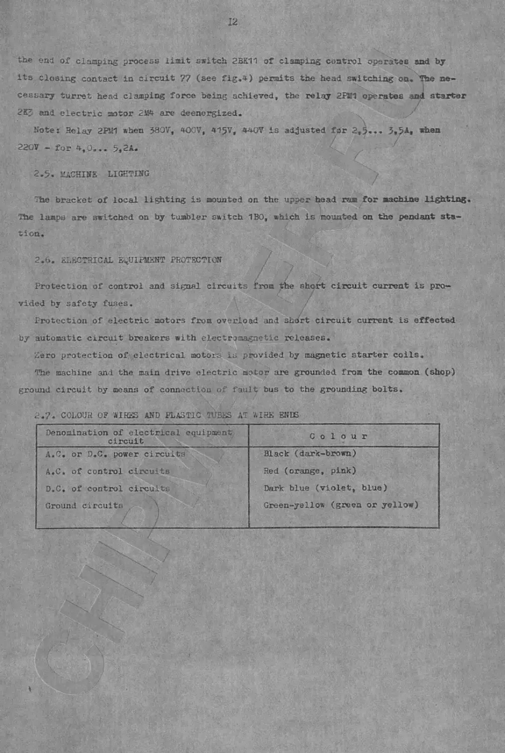
2.7. COLOUR OF AIRES AND PLASTIC TUBES AT EIRE ENDS
Denomination of electrical equipment circuit Colour
Л.С. or D.C. power circuits A.C. of control circuits D.C. of control circuits Ground circuits \ / у Black (dark-brown) Red (orange, pink) Dark blue (violet, blue) Green-yellow (green or yellow)
13
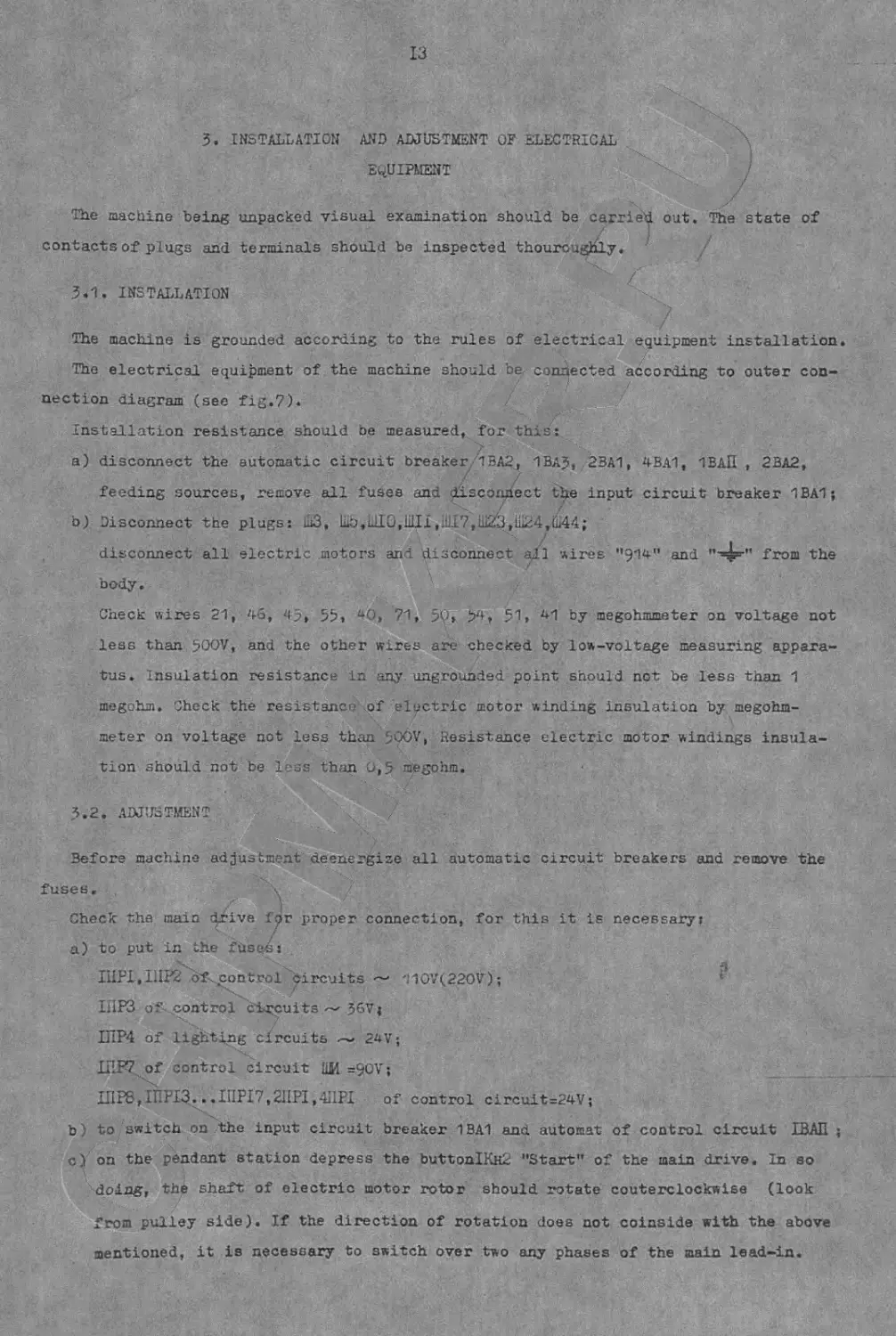
3. INSTALLATION AND ADJUSTMENT OF ELECTRICAL
EQUIPMENT
The machine being unpacked visual examination should be carried out. 'The state of
contacts of plugs and terminals should be inspected thouroughly.
3.1. INSTALLATION
The machine is grounded according to the rules of electrical equipment installation.
The electrical equipment of the machine should be. connected according to outer con-
nection diagram (see fig.7).
Installation resistance should be measured, for this:
a) disconnect the automatic circuit breaker ’1BA2, 1BA3, 23A1, 4BA1, 1ВАП , 2BA2,
feeding sources, remove all fuses and disconnect the input circuit breaker 1BA1;
b) Disconnect the plugs: ШЗ, lib, ILL 0, Uli I ,;UI7,ili23,iii24,iL44;
disconnect all electric motors and disconnect ail wires "914" and from the
body.
Check wires 21, 46, 45, 53, 40, 71, 59» 51» 41 by megohmmeter on voltage not
less than 500V, and the other wires are checked by low-voltage measuring appara-
tus. Insulation resistance in any ungrounded point should not be less than 1
megohm. Check the resistance of electric motor winding insulation by megohm-
meter on voltage not less than 5OOV, Resistance electric motor windings insula-
tion should not be less than 0,5 megohm.
3.2. ADJUSTMENT
Before machine adjustment deenergise all automatic circuit breakers and remove the
fuses.
Check the main drive for proper connection, for this it is necessary:
a) to put in the fuses:
IHP1,IIIP2 of control circuits ~ 110V(220V);
1ПРЗ of control circuits ~ 36V;
1ПР4 of lighting circuits — 24V;
II’P7 of control circuit ШИ =90V;
ШР8,1ПР13...111Р17,2ПР1,4ИР1 of control circuit=24V;
b) to switch on the input circuit breaker 1BA1 and automat of control circuit 1ВАП ;
c) on the pendant station depress the buttonlKuli "Start" of the main drive. In so
doing, the shaft of electric motor rotor should rotate couterclockwise (look
from pulley side). If the direction of rotation does not coinside with the above
mentioned, it is necessary to switch over two any phases of the main lead-in.
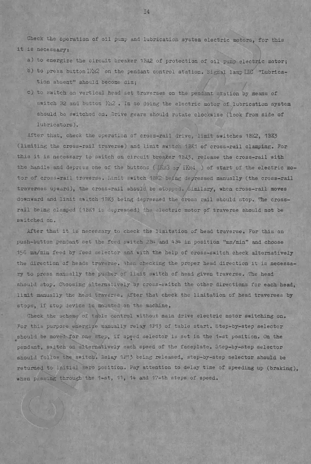
14
Check the operation of oil pump and lubrication system electric motors, for this
it is necessary:
a) to energize the circuit breaker 13A2 of protection of oil pump electric motor;
b) to press button IKh2 on the pendant control station, cigrial lamp UIC' "Lubrica-
tion absent" should become dis; f J /
c) to switch on vertical head set traverses on the pendant station by means of
switch 32 and button Kh2 • In so doing the electric motor of lubrication system
should be switched on. Drive gears should rotate clockwise (look from side of
lubricators). ; - /
After that, check the operation of cross-rail Irive, limit switches 1BK2, 1BKJ
(limiting the cross-rail traverse) and limit switch 1BK1 of cross-rail clamping. For
this it is necessary to switch on circuit breaker 1BAJ, release the cross-rail with
the handle and depress one of the buttons ( уКнЗ or 1Kh4 ) of start of the electric mo-
tor of cross-rail traverse. Limit switch 1BK2’be/ng depressed manually (the cross-rail
traverses upward), the cross-rail should be stop; • i.^imilaxy, when cross-rail moves
downward and limit switch 1BK> being depressed the cross rail should stop. The cross-
rail being clamped (1БК1 is depressed) the lectric motor of traverse should not be
switched on.
After that it is necessary to check the limitation of head traverse. For this on
push-button pendant set the feed switch 2B‘+ and 4B4 in position "mm/min" and choose
156 mm/min feed by feed selector and with the help of cross-switch check alternatively
the direction of heads traverse. Sher, checking the proper head direction it is necessa-
ry to press manually the pusher of limit switch of head given traverse. The head
should stop. Choosing alternatively oy cross-switch the other directions for each head,
limit manually the head traverse. After that check the limitation of head traverses by
stops, if stop device tfi mounted on the machine,
\ /
Check the scheme of table control without main drive electric motor switching on.
For this purpose energize manually relay 1P15 of table start. Step-by-step selector
/
should be moved for one step, if speed selector is set in the 1-st position. On the
pendant, switch on alternatively each speed of the faceplate, otep-by-step selector
should folio* the switch. Relay 1P1J being released, step-by-step selector should be
returned to. initial zero position. Pay attention to delay time of speeding up (braking)
when past.rig through the 1-st, 11, 1* and 17-th steps of speed.
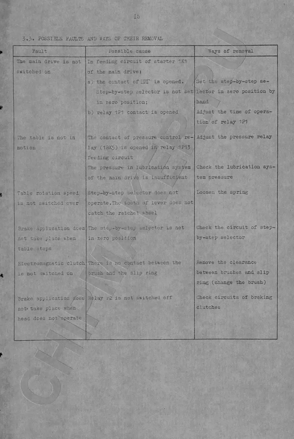
15
POSSIBLE FAULTS AND ЛАУБ OF ТНЕГН REMOVAL
Fault Possible cause Ways of removal
The oain drive is not In feeding circuit of starter TK1 /
switched on of the main drive t
a) the contact of ЛГ is opened. *Set the step-by-step se-
Step-by-step selector is not set lector in zero position by
in zero position; hand /
b) relay TFT contact is opened Adjust the time of opera-
tion of relay TP1
The table is not in The contact of pressure control re- Adjust the pressure relay
moti on lay (1BK5) is opened in’relay 1P15
feeding circuit / 7
The pressure in lubrication syst/em Check the lubrication sys-
of the main drive is insufficient \ / tern pressure
Table rotation speed Btep-by-step selector doee not Loosen the spring
is not switched over operate.The tooth of lever does not
catch the ratchet wheel
Brake application does The step-^y-step sel/ctor is not Check the circuit of step-
not take place v.hen in zero pbsbtioh by-step selector
table stops
Electromagnetic clutch There is no contact between the Remove the clearance
is not switched on brush and the slip ring between brushes and slip
ring (change the brush)
Brake application does. hplay r2 is not switched off Check circuits of braking
not' take place when clutches
head does not>aperate
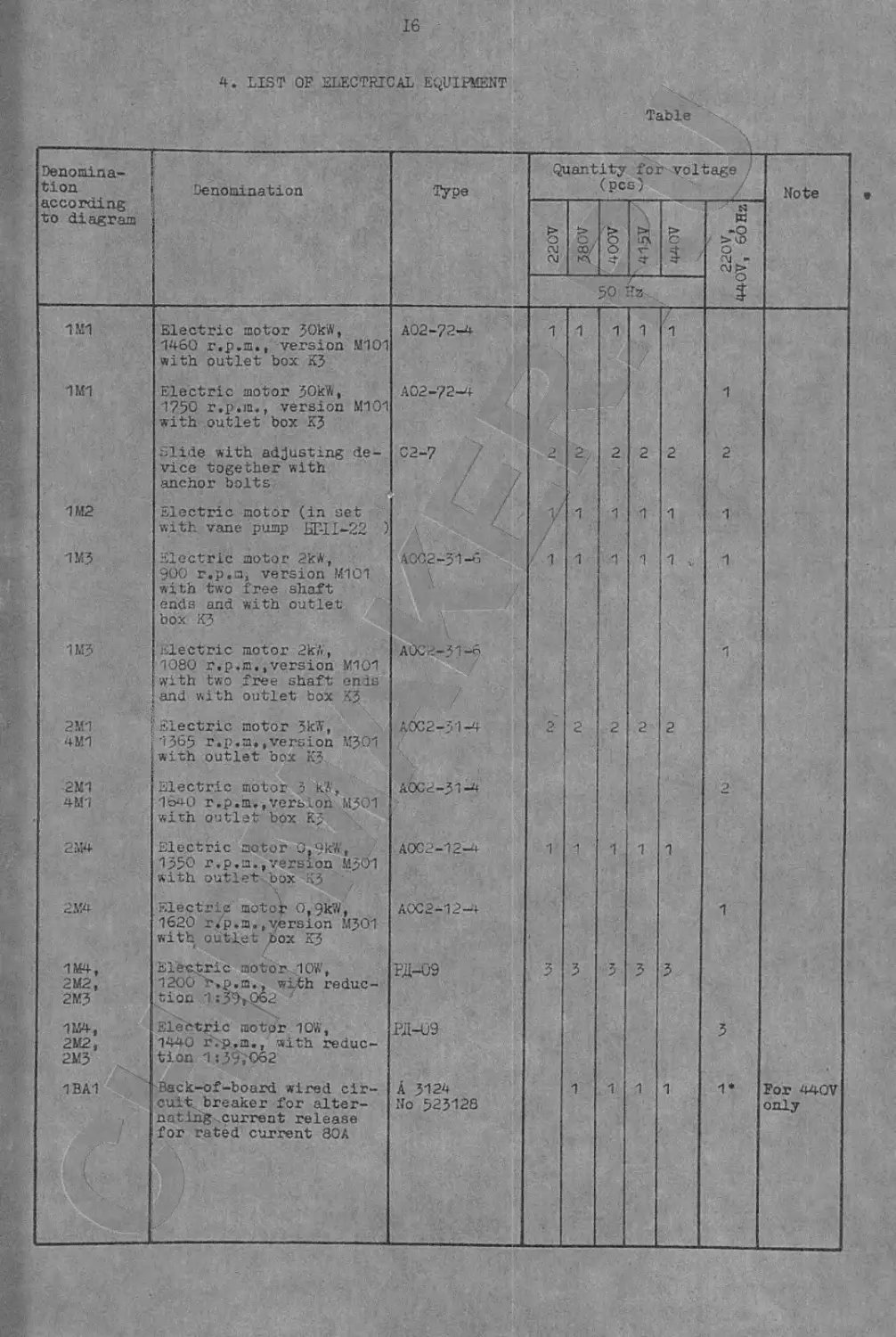
16
4. LIST OF ELECTRICAL EQUIPMENT
Table
Denomina- tion according to diagram Denomination Type Quantity for voltage (pcs) • / Note
220V Aoaf 'B о 440V 220V, 440V, 60 Hz
50 Hz
1M1 1MT 1M2 1M3 1MJ 2M1 4M1 2M1 4M1 2154 2M4 1M4, 2 М2, 2MJ 1M4, 2М2, 2MJ 1BA1 Electric motor JOkW, 1460 r.p.m., version M101 with outlet box KJ Electric motor JOk'A, 1750 r.p.m., version M101 with outlet box KJ Slide with adjusting de- vice together with anchor bolts Electric motor (in set with vane pump БГ-11—22 ) Electric motor 2k*, 900 r.p.m, version M101 with two free shaft ends and with outlet- box KJ Electric motor 2кй, 1080 r.p.m. .version МЮ1 with two free shaft ends and with outlet box KJ Electric motor 5k*, 1J65 r.p.m.,version MJ01 with outlet box KJ Electric motor J kft, 1640 r.p.m.,version MJ01 with outlet box KJ Electric motor 0,9kW, 1J50 r.p.m..version MJ01 with outlet box KJ Electric motor 0,9kW, 1620 r.p.m.,version MJ01 with outlet box KJ * / Electric motor 10W, 1200 r.p.m., with reduc- tion 1:J9>062 Electric motor 10*, 1440 r.p.m., with reduc- tion 1iJ9',O62 Back-of-board wired cir- cuit breaker for alter- nating current release for rated current 30A A02-72-4 A02-72-4 C2-7 / ACC2-J1-3 A0C2-J1-6 A0C2-J1-4 A0C2-J1-4 A0C2-12-4 ACC2-12—+ РД-09 РД-09 A J124 No 52J128 V- V;- r- Oj V- 1 2 1 1 2 3 1 1 2 1 1 2 1 3 1 1 2 1 1 2 1 3 1 1 2 1 1 V 2 1 3 1 1 2 1 1 1 2 1 3 1‘ For 440V only
17
Cont.
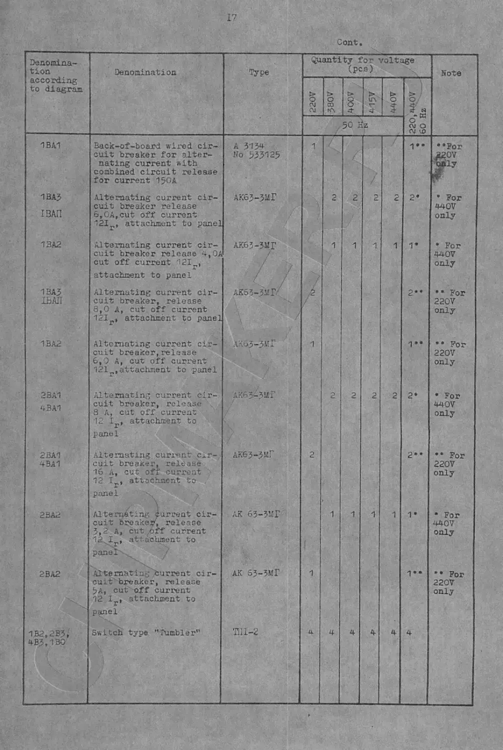
Denomina- tion according to diagram Denomination Type Quantity for voltage (pcs) Note
22OV 380V > О О 4 > in 4 > 0 J 220,440V 60 Hz
50
1BA1 1BA3 I ЗАП 1BA2 1BAJ 13АП 1BA2 2BA1 4BA1 2BA1 4BA1 2BA2 2BA2 1B2.2B3, 4BJ.1B0 Back-of-board wired cir- cuit breaker for alter- nating current with combined circuit release for current 150A Alternating current cir- cuit breaker release 6,0A,cut off current 12Ir, attachment to panel Alternating current cir- cuit breaker release u,OA cut off current 12I„, attachment to panel Alternating current cir- cuit breaker, release 8,0 A, cut off current 121 , attachment to panel Alternating current cir- cuit breaker,release 6,0 A, cut off current 121r,attachment to panel Alternating current cir- cuit breaker, release 3 A, cut off current 12 Ir, attachment to pane 1 Alternating curi-ent cir- cuit breaker, release 16 A, cut off current 12 Ip, attachment to panel \ Alternating current cir- cuit breaker', release 5,2 A, cut .off current 12..Ir, attachment to panel .. Alternating Current cir- cuit breaker, release 5A, cut off current 12 lr, attachment to panel Switch type "Tumbler” A 3134 No 535125 АК65-5МГ АК65-5МГ / / АК55-ЗМГ' лкДз-ЗМГ AKGJMMF ЛК63-5МГ ЛК 63-5МГ AK 53-5МГ fill-2 1 /2. / 1 2 1 a / 2 1 2 1 4 / 2 1 2 1 4 / / 2 1 2 1 4 2 1 2 1 4 • ♦ • • • • • • • v CM V- 1- cu GJ V- V- 4- ••For ./20V <^ily * For 440V only * For 440V only • • For 220V only * • For 220V only • For 440V only • • For 220V only • For 440V only • • For 220V only
Cent.
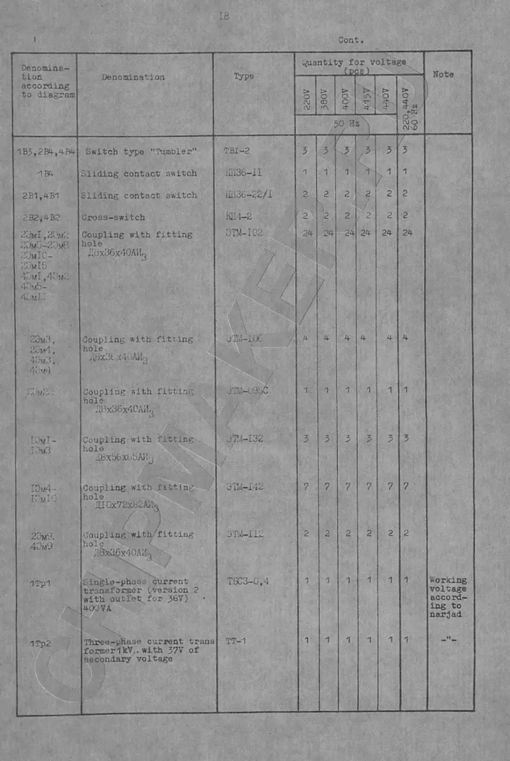
Denomina- tion according to diagram Denomination Type Quantity for voltage (pee) Note
логе > О CO •A о ? 415/ > о г 220,440V 60 Hz
50 Hz\
1B3,2B4,4B4 1B4 2B1.4B1 2B2,4B2 23м I 2Um5-2jm8 ikjmIC- 23mI5 40m! ,43m.: 43m5- 4CmI : 2ЭмЗ, :j3m4 , 43m3, 4: -z4 Сем.’;.. Л jyT_ I3m3 2Э,л-1- I'm?.’ 23мУ. 4Эм9 1Tp1 1Tp2 Switch type "Tumbler" Sliding contact switch Sliding contact switch Cross-switch Coupling with fitting hole ДохЗбх'ЮЛИ^ Coupling with fitting hole ДВх31 х4иАЙд Coupling with fitting hole „X ДВх36х40ЛИ.. Coupling with fitting hole 48xb6Xb5AHj Coupling with fluting hole Д10x72x82 A>\ ) Coupling with'fitting hole 4, ;аЫ§х4оли3 " ? Single-phao. current ttonsformeг (version 2 with outfit.. for 36V) 400 V A Three-phase current trans formerlkV.. with 37V of secondary voltage TBi-2 1Ш36-11 inI35-22/l КД4-4 C’TM-102 JTM-li.c 3 -hi—CAR>C 374-132 / «ji*/1—112 3 lui—11** ТБСЗ-0,4 TT-1 4- У ГЛ V OJ PJ CV \ 4 г- н\ ГМ v- r- K\ V (\j _<XI ?4 4 Г- ГЛ Сч OJ V Г“ / 1 2 2 24 4 1 3 7 2 1 1 24 4 1 5 7 2 1 1 0? -Л -д К) км -> -Р 4? Го Ю -л кН / 3 1 2 •2 24 4 1 3 7 2 1 1 Working voltage accord- ing to narjad
19
Cont.
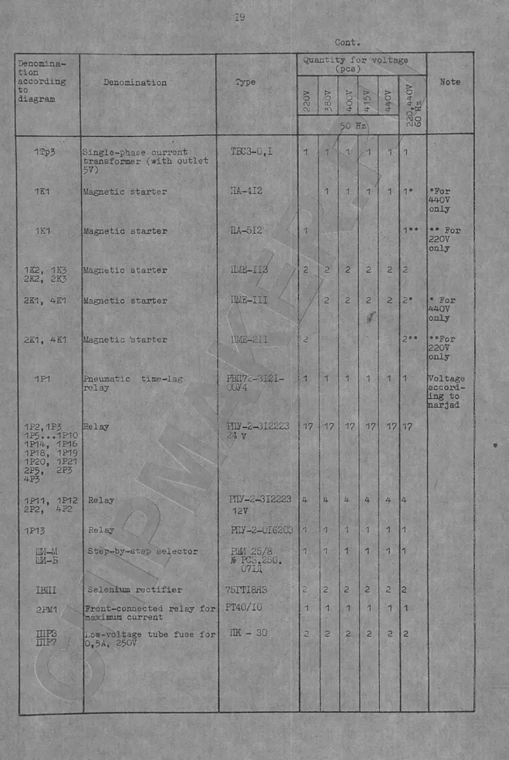
Denomina- tion according to diagram Denomination Type Quantity for voltage (pcs) Note
> 0 OJ Cki % □3 мл 4- > d* 5 Г” 220,440V 60 Hz
50 Hz
1Tp? 1K1 1K1 122, 1K5 2K2, 2 KJ 2K1, 4K1 221, 4K1 1P1 1P2.1PJ 1P5...1P1O 1P14, 1P16 1P18, 1P19 1P2O, 1P21 2P5, 2P3 4PJ 1P11, 1P12 2P2, 4?2 1P1J ШИ-М 1М-Б 1ВП1 2PM1 HIPS ШР7 / Single-phase current transformer (with outlet 5V) Magnetic starter Magnetic starter Magnetic starter Magnetic starter Magnetic ‘startei’ Pneumatic time-lag relay Relay Relay -> \ Relay Step-by-step selector Selenium rectifier Front-connected relay for maximum current Low-voltage tube fuse for 0,5A, 250V TBC3-G.I ILA-412 ПА-512 ИЖ-ИЗ'' W-iii 1LVJS-21I A FBI171—3121- 70У4 П1У-2-^12223 24 V ГПУ-2-312223 12V И1У-2-01620; РЖ 25/8 Я PCS.250. 07U 75ГТ18НЗ PT40/IU UK - 30 f 1 1 2 / 1 17 4 1 1 2 1 1 " 1 2 2 1 17 4 1 2 1 2 <1 1 2 2 1 17 4 1 1 2 1 2 1 1 ‘ 2 2 / 1 17 4 1 1 2 1 2 '1,y 1 2 2 1 17 4 1 1 2 1 2 1 1» 1” 2 2е 2” 1 17 4 1 1 2 1 2 •For 440V only •• For 220V only * For 4-40V only ••For 220V only Voltage t accord- } ing to card ad I
20
Cont.
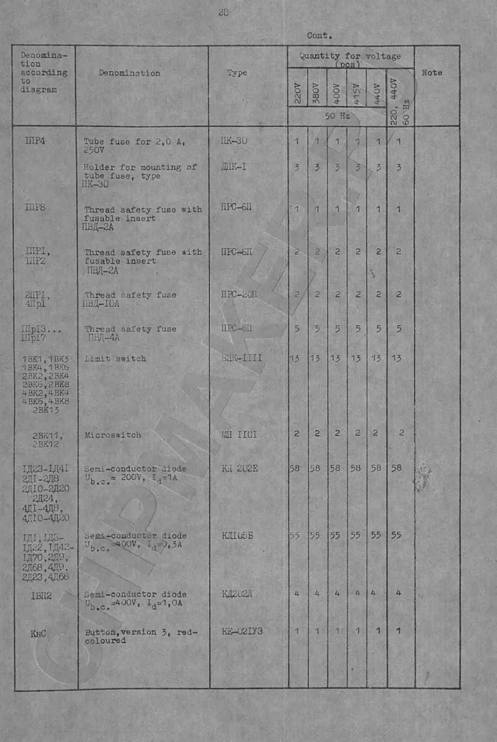
Denomina- tion according to diagram Denomination Type Quantity for voltage foes’) Note
220V 580V 400V > О 1 220, 440V 60 Hz
50 Hz
IiIP4 Д1Р8 IIIPI, П1Р2 2ПЙ, 411 pl !Hpl3... UIp£7 13K1,1BK5 5 3K4,1 BK6 2BK2.2BK4 2BK6.2BK8 4BK2,4BK4 4BK6.4BK8 2BK13 2BK11, 2BK12 1Д23-1Д41 2Д1-ЭД8 ЭД10-2Д20 2Д24, 4П1-4Д8, 4ДЮ-4Д20 1Д1,1ДЗ- 1Д22.1Д42- 1Д70.ЭД9, 2Д68.4Д9, 2Д23.4Д68 IBII2 КнС Tube fuse for 2,0 A, 250V Holder for mounting of tube fuse, tyoe IIK-30 Thread safety fuse with fusable insert ГШД-2А Thread safety fuse with fusable insert [ЩЦ-2Л Thread safety fuse 1ШД-10Л Thread safety fuse ПВД-4А Limit switch Microswitch Semi-conductor diode U. , 3 200V, I.=1A b.C. ’ 4 \ / / • J / \ / oeiG-L-couductur diode и =;4Q0V, I,=Q, pA Semi-conductor diode Ub.c.-400V’ Ч=1’0А Button,version 5, red- coloured iIK-30 ДИК-1 ПРС-611 ПРС-6П . / / / ПЕС-2Й1 UPC-Gil Жк-iiii Ш HUI КД 282E КД105Б КД202/1 КВ-021УЗ 1 3 1 2 2/ 5 13 2 58 55 4 1 V- TT ru . CM LA H\ OJ CO U> r- /\ ir\ u\ 1 3 1 2 2 5 13 2 58 55 4 1 > 1 3" 1 2 2 5 13 2 58 55 4 1 1 : 3 1 2 2 5 13 2 58 55 4 1 1 3 1 2 2 5 13 2 58 1 4 1
21
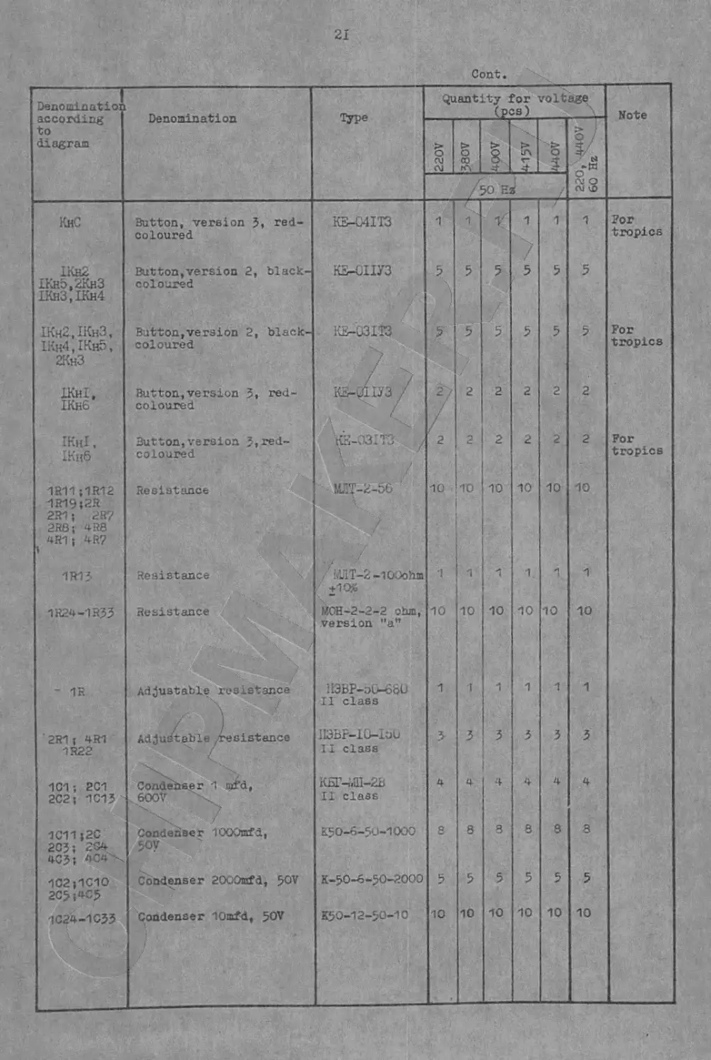
Cont.
1 Denominatioi according to diagram Denomination Quantity for voltage (pcs) Note
220V . 380V > 8. 4- 50 E / л£Иг ... w 0 l£ / ITT i o-“ Л! О см чЭ
KhC Button, version 3, red- coloured KS-C4IT3 1 1х 1' 1 7 1 1 For tropics
LKh2 IKh5,2Kh3 IKh3,IKh4 Button,version 2, black- coloured КЕ-ОПУЗ 2 5 5 5 5 5
IKh2,IKh3, IKh4,IKho, 2Kh3 Button,version 2, black- coloured i'3-u3iT3 5 5 5 3 5 For tropics
IKhI, IKh6 Button,version 3, red- coloured Ытошз / 7 2 2 2 2 2
IKhI , IKn6 Button,version 3,red- coloured КБ-031ТЗ / \ / 2 2 2 2 2 2 For tropics
1R11 ;1R12 1R19;2R 2R1; 2R7 2RB; 4R8 4R1; 4R7 » Resistance MIT-2-56 / 10 10 10 10 10 10
1R13 Resistance / i«UlT-2-lOOohm 1 1 1 1 1 1
1R24-1R33 Resistance ЙОН-2-2-2 ohm, version "a" 10 10 10 10 10 10
- 1R Adjustable resistance x A • ' / :i3bP-uG-66U Il class 1 1 1 1 1 1
'2R1 ; 4R1 1R22 Adjustable resistance IDBP-iO-lUb II class 3 3 3 3 3
101; 201 202j 1013 Condehaer 1 nxfd, .600V КБГ-МП-2В II class 4 4 4 4 4 4
1011;2C 203; 204 403; 4C4 -x Condenser lOOOmfd, 50V K.5O-6-S0-IOOO 8 8 3 8 8 S
1C2;1C10 2C>;4C5 Condenser 20G0njfd, 50V K-50-6-5O-2OOO 5 5 5 5 5 5
1C24-1C33 Condenser 10mfd, 50V K50-12-50-10 10 10 10 10 10 10
22
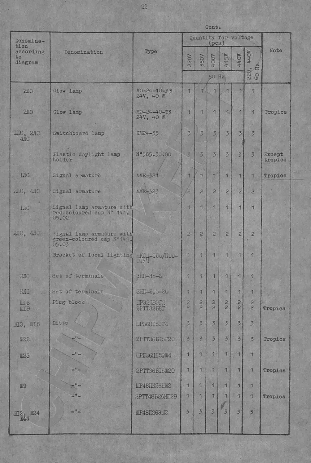
Cont,
Denomina- tion according ’Denomination Type Quantity for voltage (pcs) Note
> > t> §
t/O diagram 0 rv rj 0 co 0 c 3- V 0 >, 44 Hz
50 HZj 22C 60
2Л0 Glow lamp MO-24-40-yj 24V, 40 W 1 1 1 x 1 1 1
2J10 Glow lamp M0-24-40-TJ 24V, 40 W 1 1 1 1/ 1 1 Tropics
LttC, 2ЛС 4ЛС Switchboard lamp Ю424-35 3 3 3 3 3 3
Plastic daylight lamp holder №565.30.00 / / 3 3 3 3 3 3 Except tropics j
LIC Signal armature / / AKE-321 1 1 1 1 1 1 Tropics i J
2ЛС, LiC signal armature AME-323 /2 2 2 2 2 2 - !
LiC Signal lamp armature with red-coloured cap № 141» 05.02 1 1 1 1 1 1
Lie, Liu Signal lamp armature with green-coloured cao №141. 05.05 2 2 2 2 2 2
Bracket of local lighting 1 1 1 1 1 1
к.10 Set of terminals ЗНП-35-6 1 1 1 1 1 1
ieii Set of terminals 3HU-2, u-2U 1 1 1 1 1 1
И6 11Я9 Plug block 1 Я \ -*1-/ / 1 ШР32П83Г2 2РТТ32Б8Г 2 2 2 2 2 2 2 2 2 2 2 Tropics
11ЦЗ, dI8 Ditto / Ж»Щ5Э.Г4 3 3 3 3 3 3
Ы22 2РГТ36БЬГ20 3 3 3 3 3 3 Tropics
Ш23 7 шРГЗбЦ150Ш4 1 1 1 1 1 1
2РТТ36Б15Ш20 1 1 1 1 1 1 Tropics
Ш9 UP48IiK26i!iu2 1 1 1 1 1 1
—n — 2РТГ48Б26НШ29 1 1 1 1 1 1 Tropics
Ш12, Ш24 Ш44 ШР48П26ЭШ2 3 3 3 3 3 3
23
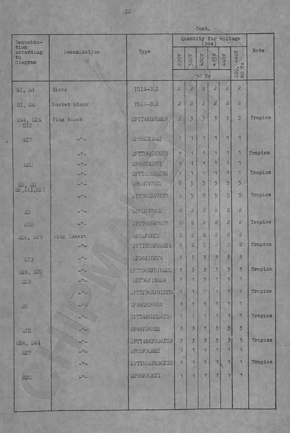
Cont.
Denomina- tion according to diagram Denomination ~x4; Type Quantity for voltage (pcs) Note
§ OJ Cd 6 и КЧ > § V- lA г- о & I 5/ • tr
./50 rj OJ О AJ 40
WI, Ш4 Uli, Ш4 Ш44, Ш24 Ш12 Ш17 шги til? uE> ,11111^11121 ШЗ Ш10 uilb, all 9 Ш13 Ji 8, 11122 11123 Ш9 11112 U24, Ш44 11117 . ш?о Block Socket block Plug block — Ш. Plug insert / ) 4 / i РП14-30Л Ш14-ЗЫ1 2РГТ40Б26Ш29.. / uii'56fl303iiil / . 2РТТЪб/301;!33 шР55ПЭДГ1- г^ТТ55БЗиГ32 и1Р6Ш47ЭГ2 / 2РТТ6Ж7Г37 1мР£’л1 : 2РТТ60Б47Ш37 и1Р32У8НГ2 21ТТ32КУНси114 Ц1Р36У15ИГ4 2РТГ36КУН15Ш20 лРГ36УШ1Ы 2РТТГ36КШ5Й1 'ДЦ8ЦК26НШ2 2РТТ48К111126Г29 ШР48У261Ш12 2РТТ48КУН26Г29 шР55УЗиШ 2ИТ55КУН30Г32 1ИР55УЗЫ1Г1 2 2 A -1 V /1 5 5 2 2 2 3 3 1 1 1 1 3 3 1 1 1 г 2 3 1 /<1 1 1 5 5 2 2 2 2 3 3 1 1 1 1 3 3 1 1 1 <м нч г- т-г-г-ачич <\i cj c\i i'j кч г- т- г- t- кл кч г- т- 2 2 3 1 1 1 1 5 5 2 2 2 2 3 3 1 1 1 1 3 3 1 1 1 ' .2 2 3 1 1 1 1 5 5 2 2 2 3 3 1 1 т 1 3 3 1 . 1 г 1 2 2 3 1 1 1 1 5 • 5 2 2 2 2 3 3 1 1 1 1 3 3 "4. 1 1 Tropics Tropics Tropics Tropics Tropics Tropics Tropics Tropics Tropics Tropics Tropics
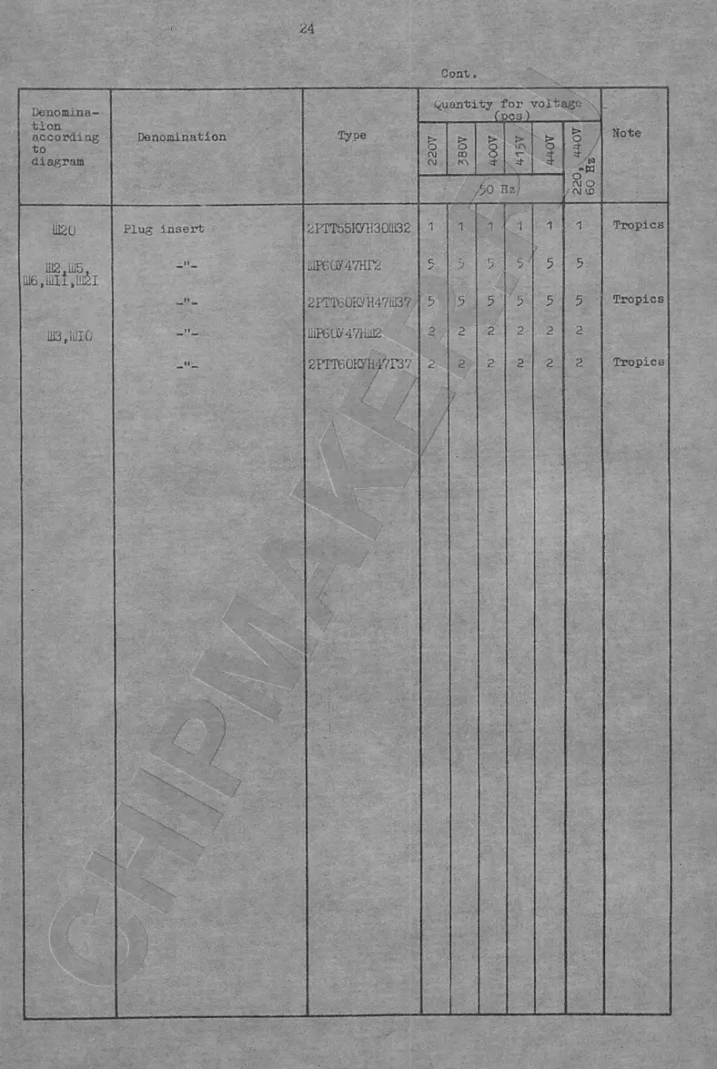
24
25
technical control department
ACCEPTANCE TEST CERTIFICATE
\
ELEC T-R- I -C AL, EQUIPMENT
SINGLE-COLUMN
VERTICAL TURNING AND BORING MILL
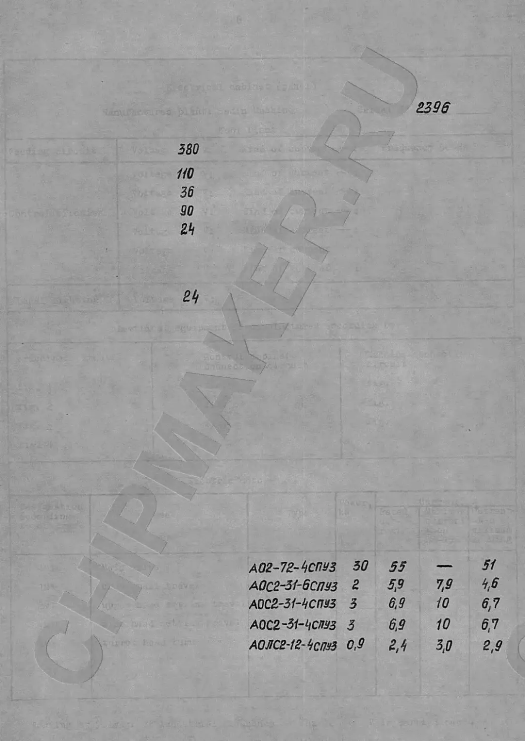
2395
580
НО
36
90
24
24 \
А02-72-9СПУЗ 50 55 — 51
А0С2-51-6СПУЗ 2 5.9 7.9 9,6
А0С2-31-9СПУЗ 3 6.9 10 6,7
A0C2-31-iiCW3 3 6,9 10 6.7
АОЛСВ-1г-9сИУЗ 0,9 г,^ 3.0 2.9
27
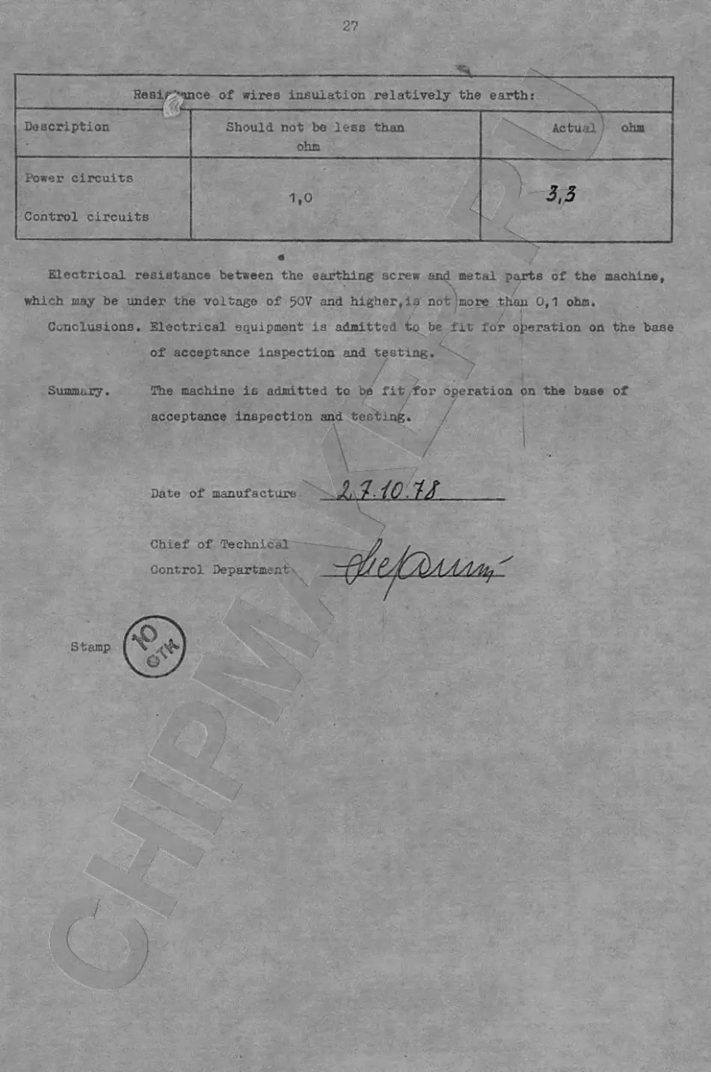
Electrical resistaace between the earthing screw and metal parts of the machine,
which may be under the voltage of 50V and higher,ia not!more than 0,1 ohm.
/ . - /- *
Conclusions. Electrical equipment is admitted to be fit for operation on the base
of acceptance inspection and testing.
/ 2 <
Summary. The machine is admitted to be fit,for operation on the base of
acceptance inspection and testing. /
Date of manufacture 1,ио.и____________________